1
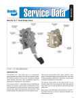
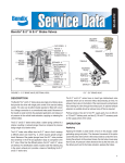
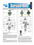
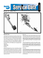
SD-03-816
®
Bendix® E-5™ Brake Valve
12
13
10
9
7
6
11
8
5
1
4
2
3
FIG. 1
FIG. 2
DESCRIPTION
Balanced
The Bendix® E-5™ brake valve is a single circuit brake valve
that provides the driver with single point control of the service
brake system. The valve is a suspended pedal operated
valve, normally mounted on the engine firewall within the
vehicle cab. Porting consists of 7 supply ports, 4 delivery
ports, and one (1) 1/8 in. P.T. auxiliary supply port. Additional
identified delivery and supply ports serve as a manifold for
accessory devices. The exhaust port is equipped with a
diaphragm.
When air pressure in the cavity beneath the piston and the
air pressure being delivered to the brake actuators equals
the mechanical force on the top of the piston, the piston lifts
and the inlet valve closes, stopping any further flow of air
from the supply line through the valve. The exhaust remains
closed, preventing any escape of air through the exhaust
port.
OPERATION
Applying
Applying the pedal exerts a force on the plunger, through
the rubber graduating spring and to the piston. The piston
moves and its stem, which is the exhaust seat, closes the
exhaust. As the exhaust closes, the inlet valve moves off its
seat. Air pressure from the reservoir then flows in by the
inlet valve and out the delivery ports to the air chambers
applying the brakes.
When brake applications are made in the graduation range,
the valve reaches a balanced position as the air pressure
beneath the piston equals the effort exerted by the driver’s
foot on the pedal. When the piston is fully depressed, the
inlet valve remains open and reservoir pressure is delivered
to the air chambers.
Releasing
If the pedal application is released and mechanical force is
removed from the top of the piston, the force produced by
the air pressure beneath the piston is then greater, and the
piston lifts, opening the exhaust in the valve. The air below
the piston and in the delivery lines is then exhausted through
the exhaust port.
PREVENTIVE MAINTENANCE
Important: Review the warranty policy before performing
any intrusive maintenance procedures. An extended warranty
may be voided if intrusive maintenance is performed during
this period.
Because no two vehicles operate under identical conditions,
maintenance and maintenance intervals will vary. Experience
is a valuable guide in determining the best maintenance
interval for any one particular operation.
Visually check for physical damage to the brake valve such
as broken air lines and broken or missing parts.
Every 3 Months, 25,000 Miles or 900 Operating Hours
Lubricate all pedal actuation parts with light (10W) oil. Check
free pedal travel. If necessary, adjust stop button so that
roller just contacts plunger.
SERVICE TESTS
Operating Test
NOTE: IMPORTANT!!! Tests should be conducted with an
accurate test gauge.
Install gauge in a delivery port or line; depress the treadle or
pedal to several positions between fully released and fully
applied positions, checking the delivery pressure on the
gauge to see that it varies proportionately with the movement
of the treadle or pedal. In the fully applied position, the
reading on the gauge should be approximately that of full
reservoir pressure. Upon release of the application, the
reading of the test gauge should fall to zero psi immediately.
Leakage Test
With 100 psi supply pressure and valve in released position,
coat exhaust port with soapsuds and check for leakage.
NO leakage permitted.
Fully apply valve and hold application. Coat exhaust port
with soapsuds. NO leakage permitted. Coat area around
plunger and valve body with soapsuds. NO leakage
permitted.
For removal of internal parts only - remove the pedal
and mounting plate assembly. Press up on the valve retainer
and release the locking tabs from the body (CAUTION: piston
is spring loaded); piston assembly, inlet valve seat, and the
inlet/exhaust valve assembly may now be removed from the
valve body.
Installing
Clean air lines to valve.
Install valve and tighten mounting nuts and cap screws.
Connect air lines to valve (plug any unused ports).
Test valve as outlined under “Service Tests.”
DISASSEMBLY
Pedal and Mounting Plate
1. Remove cotter pin from fulcrum pin (1) and remove
fulcrum pin and pedal.
2. Remove cotter pin from roller pin (2), remove roller pin.
Remove pedal cover (3).
3. Remove mounting plate cap screws (4). Remove
mounting plate with plunger. Plunger, stop button, and
stop button lock nut may now be removed from mounting
plate.
Basic E-5™ Brake Valve
4. Depress retainer (5) and release retainer tabs from body
grooves. Remove retainer. (CAUTION: Piston (6) is
loaded by return spring (7).)
5. Remove piston assembly (6) and piston return spring
(7).
6. Remove inlet seat (8). Remove o-rings from the inlet
seat.
7. Remove inlet/exhaust valve (9) and spring (10).
8. Remove o-ring (11) from piston assembly (6). Remove
cap screw, washer, spring seat, and rubber spring from
piston.
9. Remove inlet valve stem o-ring (12) and valve retainer
from inlet/exhaust valve assembly.
10. Remove exhaust check valve diaphragm (13).
Cleaning and Inspection
If the valve does not function as described or leakage is
excessive, it is recommended that it be replaced with a new
or remanufactured unit, or repaired with genuine Bendix
parts available at Bendix outlets.
1. Wash all metal parts in mineral spirits and dry. Wipe all
rubber parts clean.
2. Inspect all parts for excessive wear or deterioration.
3. Inspect valve and valve seats for nicks and burrs.
REMOVING AND INSTALLING
Removing
Block and hold vehicle by means other than air brakes. Drain
air brake system.
For complete valve removal - disconnect all air lines in
the cab and at the firewall from the brake valve. Remove
mounting nuts and cap screws; remove valve.
2
4. Check springs for cracks, distortion or corrosion.
5. Inspect bore of body for scratches or out of round
condition. Replace as necessary.
6. Inspect all pedal parts and mounting plate for wear;
replace as necessary.
Replace all parts not considered serviceable. It is
recommended that all rubber parts be replaced.
Maintenance Kits containing all necessary detail parts are
available from Bendix outlets. Consult the Bendix catalog
for piece numbers.
ASSEMBLY
Basic E-5™ Brake Valve
1. Lightly lubricate body bores, inlet/exhaust valve stem,
o-rings, inlet seat, and piston with Dow Corning 55-M
pneumatic grease (Bendix piece number 291126).
2. Install rubber spring in piston (as shown in illustration);
install seat (with convolution towards rubber spring) on
rubber spring. Install washer and cap screw. Torque
cap screw to 50 inch pounds.
3. Install piston o-ring (11) on piston assembly.
4. Install valve retainer and stem o-ring on inlet/exhaust
valve assembly.
5. Install inlet valve spring (10) in body; install inlet/exhaust
valve assembly (9) in bore of body.
6. Instal o-rings on inlet valve seat (8) and install in body so
tab in seat lines up with its slot in the body.
7. Install piston return spring (7) in inlet seat.
8. Install piston assembly (6); while exerting pressure on
piston, install retainer (5); make certain retainer tabs
snap into place in grooves of body.
Pedal and Mounting Plate
9. Lightly lubricate plunger, plunger bore, fulcrum, roller
pins, and all pedal actuation contact points with
Molybdenum Disulfide grease (Bendix piece number
239378).
10. Install stop button and lock nut in mounting plate.
11. Install rollers on pedal with roller pin, secure pin with
cotter pin.
12. Connect pedal to mounting plate with fulcrum pin (1);
secure fulcrum pin with cotter pin.
13. Install plunger in mounting plate; install pedal cover (3).
14. Attach pedal/mounting plate assembly to valve body with
cap screws (4). Torque cap screws to 80-120 inch pounds.
15. Adjust free pedal travel so that the rollers just contact
the plunger by adjusting the stop button. Tighten lock
nut when adjustment is complete.
Testing Rebuilt E-5™ Brake Valve
Perform Operating and Leakage Tests as outlined in “Service
Test” section.
WARNING! PLEASE READ AND FOLLOW
THESE INSTRUCTIONS TO AVOID
PERSONAL INJURY OR DEATH:
When working on or around a vehicle, the following
general precautions should be observed at all times.
1. Park the vehicle on a level surface, apply the
parking brakes, and always block the wheels.
Always wear safety glasses.
2. Stop the engine and remove ignition key when
working under or around the vehicle. When
working in the engine compartment, the engine
should be shut off and the ignition key should be
removed. Where circumstances require that the
engine be in operation, EXTREME CAUTION should
be used to prevent personal injury resulting from
contact with moving, rotating, leaking, heated or
electrically charged components.
3. Do not attempt to install, remove, disassemble or
assemble a component until you have read and
thoroughly understand the recommended
procedures. Use only the proper tools and observe
all precautions pertaining to use of those tools.
4. If the work is being performed on the vehicle’s air
brake system, or any auxiliary pressurized air
systems, make certain to drain the air pressure from
all reservoirs before beginning ANY work on the
vehicle. If the vehicle is equipped with an AD-IS™
air dryer system or a dryer reservoir module, be
sure to drain the purge reservoir.
5. Following
the
vehicle
manufacturer’s
recommended procedures, deactivate the electrical
system in a manner that safely removes all
electrical power from the vehicle.
6. Never exceed manufacturer’s recommended
pressures.
7. Never connect or disconnect a hose or line
containing pressure; it may whip. Never remove a
component or plug unless you are certain all
system pressure has been depleted.
8. Use only genuine Bendix ® replacement parts,
components and kits. Replacement hardware,
tubing, hose, fittings, etc. must be of equivalent
size, type and strength as original equipment and
be designed specifically for such applications and
systems.
9. Components with stripped threads or damaged
parts should be replaced rather than repaired. Do
not attempt repairs requiring machining or welding
unless specifically stated and approved by the
vehicle and component manufacturer.
10. Prior to returning the vehicle to service, make certain all components and systems are restored to
their proper operating condition.
3
BW1565 © 2004 Bendix Commercial Vehicle Systems LLC. All rights reserved. 3/2004 Printed in U.S.A.