1
PREVENTIVE MAINTENANCE
Important: Review the warranty policy before performing
any intrusive maintenance procedures. An extended warranty
may be voided if intrusive maintenance is performed during
this period.
Because no two vehicles operate under identical conditions,
maintenance and maintenance intervals will vary. Experience
is a valuable guide in determining the best maintenance
interval for any one particular operation.
Visually check for physical damage to the brake valve such
as broken air lines and broken or missing parts.
Every 3 Months, 25,000 Miles or 900 Operating Hours
Lubricate all pedal actuation parts with light (10W) oil. Check
free pedal travel. If necessary, adjust stop button so that
roller just contacts plunger.
SERVICE TESTS
Operating Test
NOTE: IMPORTANT!!! Tests should be conducted with an
accurate test gauge.
Install gauge in a delivery port or line; depress the treadle or
pedal to several positions between fully released and fully
applied positions, checking the delivery pressure on the
gauge to see that it varies proportionately with the movement
of the treadle or pedal. In the fully applied position, the
reading on the gauge should be approximately that of full
reservoir pressure. Upon release of the application, the
reading of the test gauge should fall to zero psi immediately.
Leakage Test
With 100 psi supply pressure and valve in released position,
coat exhaust port with soapsuds and check for leakage.
NO leakage permitted.
Fully apply valve and hold application. Coat exhaust port
with soapsuds. NO leakage permitted. Coat area around
plunger and valve body with soapsuds. NO leakage
permitted.
For removal of internal parts only - remove the pedal
and mounting plate assembly. Press up on the valve retainer
and release the locking tabs from the body (CAUTION: piston
is spring loaded); piston assembly, inlet valve seat, and the
inlet/exhaust valve assembly may now be removed from the
valve body.
Installing
Clean air lines to valve.
Install valve and tighten mounting nuts and cap screws.
Connect air lines to valve (plug any unused ports).
Test valve as outlined under “Service Tests.”
DISASSEMBLY
Pedal and Mounting Plate
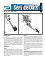
1. Remove cotter pin from fulcrum pin (1) and remove
fulcrum pin and pedal.
2. Remove cotter pin from roller pin (2), remove roller pin.
Remove pedal cover (3).
3. Remove mounting plate cap screws (4). Remove
mounting plate with plunger. Plunger, stop button, and
stop button lock nut may now be removed from mounting
plate.
Basic E-5™ Brake Valve
4. Depress retainer (5) and release retainer tabs from body
grooves. Remove retainer. (CAUTION: Piston (6) is
loaded by return spring (7).)
5. Remove piston assembly (6) and piston return spring
(7).
6. Remove inlet seat (8). Remove o-rings from the inlet
seat.
7. Remove inlet/exhaust valve (9) and spring (10).
8. Remove o-ring (11) from piston assembly (6). Remove
cap screw, washer, spring seat, and rubber spring from
piston.
9. Remove inlet valve stem o-ring (12) and valve retainer
from inlet/exhaust valve assembly.
10. Remove exhaust check valve diaphragm (13).
Cleaning and Inspection
If the valve does not function as described or leakage is
excessive, it is recommended that it be replaced with a new
or remanufactured unit, or repaired with genuine Bendix
parts available at Bendix outlets.
1. Wash all metal parts in mineral spirits and dry. Wipe all
rubber parts clean.
2. Inspect all parts for excessive wear or deterioration.
3. Inspect valve and valve seats for nicks and burrs.
REMOVING AND INSTALLING
Removing
Block and hold vehicle by means other than air brakes. Drain
air brake system.
For complete valve removal - disconnect all air lines in
the cab and at the firewall from the brake valve. Remove
mounting nuts and cap screws; remove valve.
2
4. Check springs for cracks, distortion or corrosion.
5. Inspect bore of body for scratches or out of round
condition. Replace as necessary.
6. Inspect all pedal parts and mounting plate for wear;
replace as necessary.