1
SD-22-3260
®
Bendix® Double Anchor Pin Cam Brake
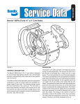
FIGURE 1
GENERAL DESCRIPTION
OPERATION
The Bendix 16-1/2” x 7” double anchor pin cam brake is
designed for use on heavy duty highway vehicles. It is a
mechanically actuated, leading /trailing shoe brake with a
fixed position cam and anchors.
The Bendix cam brake operates in the following manner
during a braking application. The force of the push rod of
the actuator is converted from a linear force to a rotary
torque. This is accomplished by use of the slack adjuster.
This torque is transferred to the cam shaft of the foundation
brake due to the spline of the cam shaft being connected to
the gear of the slack adjuster. On the opposite end of the
cam shaft is the S-Cam which when rotated lifts the cam
rollers. This spreads the brake shoe ends apart and pivots
the shoes about the anchor pin so the brake lining comes
in contact with the rotating brake drum. The friction created
by the lining pressure against the drum generates the torque
necessary to provide a retarding force to slow down the
vehicle. The energy of the vehicle in motion is converted to
heat at the surface of the drum and lining. The heat raises
the temperature of the drum. The heat is stored in the drum
and finally dissipated to the air.
The brake consists of two fabricated steel shoe assemblies
individually anchored to a cast iron torque spider and
actuated by a single forged cam shaft. Two retaining springs
secure the shoe assemblies to their respective anchor pins.
The twin webs of each shoe assembly engages the anchor
pin on one end and the cam roller on the other. A single
shoe to shoe return spring is used to maintain constant
contact between the shoe, cam roller and cam.
1
26
25
4
24
2
1
23
2
7
8
3
9
13
17
10
11
16
6
28
29
5
22
30
8
18
12
9
19
13
15
14
20
27
21
FIGURE 2 - 16-1/2” DOUBLE ANCHOR PIN S-CAM BRAKE
Key No.
1
2
3
4
5
6
7
8
9
10
11
12
13
14
15
2
Description
Snap ring
Spacer washers
Yoke pin
Slack adjuster
Yoke
Cotter pin
Washer
Grease seal
Bushing
Cap screw
Lock washer
Actuator bracket and cam tube
Brake shoe assembly
Cam roller
Cam roller bushing
Qty.
Key No.
1
#reqd.
1
1
1
1
1
2
2
4
4
1
2
2
2
16
17
18
19
20
21
22
23
24
25
26
27
28
29
30
Description
Anchor pin
Anchor pin bushing
S-Cam shaft
Cam head washer
Shoe return spring
Spring retainer pin
Anchor spring
Dust shield
Rubber inspection plug
Cap screw
Star washer
Actuator
Nut
Washer
Sealing Ring
Qty.
2
2
1
1
1
2
2
2
2
6
6
1
2
2
1
PREVENTIVE MAINTENANCE
1. BRAKE ADJUSTMENT
Weekly, or whenever push rod stroke exceeds maximum
distance listed on the following chart. For complete
adjustment information, see Bendix Service Data Sheet
SD-05-1.
Ser- Service
Max.
vice Diaphragm
Stroke
Act- Effective
With
uator
Area
Outside Max.
Brakes
Type (Sq. In.) Diameter Stroke Adjusted
24
30
24
30
7-7/32
8-3/32
2-1/4
2-1/2
short as
possible
without
brakes
dragging
Full Pressure
Max. Stroke
at which
Brakes
Should Be
Readjusted
1-3/4
2
2. BRAKE LUBRICATION
Grease camshaft bracket with vehicle manufacturer’s
recommended chassis lube. Lube once every six months
or at each chassis lubrication.
3. BRAKE RELINE
The life of the brake lining is dependent on many factors
such as the material of the lining, type of operation the
vehicle is used for, and the driver of the vehicle. If driving
conditions require frequent braking, lining replacement
will be required more often. Reline when lining thickness
at center of shoe is 1/4”. Refer to section “Reline
Procedure”.
4. BRAKE OVERHAUL
As often as necessary to maintain adequate brake
performance. NOTE: When overhauling brake system,
provide equal service to all drive axle brakes on the
vehicle.
WARNING! PLEASE READ AND FOLLOW
THESE INSTRUCTIONS TO AVOID PERSONAL
INJURY OR DEATH:
When working on or around brake systems and
components, the following precautions should be
observed at all times:
3. Do not attempt to install, remove, disassemble or
assemble a component until you have read and
thoroughly understand the recommended
procedures. Use only the proper tools and observe
all precautions pertaining to the use of those tools.
4. Following
the
vehicle
manufacturer’s
recommended procedures, deactivate the electrical
system in a manner that safely removes all
electrical power from the vehicle.
5. If the vehicle is equipped with an air over hydraulic
brake system or any auxiliary pressurized air
system, make certain to drain the air pressure from
all reservoirs before beginning ANY work on the
vehicle. If the vehicle is equipped with an AD-IS™
air dryer system or a dryer reservoir module, be
sure to drain the purge reservoir.
6. Never connect or disconnect a hose or line
containing pressure; it may whip. Never remove a
component or pipe plug unless you are certain all
system pressure has been depleted.
7. Never exceed manufacturer’s recommended
pressure.
8. Never attempt to disassemble a component until
you have read and understand all recommended
procedures. Some components contain powerful
springs and injury can result if not properly
disassembled. Use only proper tools and observe
all precautions pertaining to use of those tools.
9. Use only genuine Bendix ® replacement parts,
components and kits.
A. Use only components, devices and mounting
and attaching hardware specifically designed
for use in hydraulic brake systems.
B. All replacement hardware, tubing, hose,
fittings, etc. must be of equivalent size, type
and strength as the original equipment.
10. Components with stripped threads or damaged
parts should be replaced rather than repaired. Do
not attempt repairs requiring machining or welding
unless specifically stated and approved by the
vehicle and component manufacturer.
11. Prior to returning the vehicle to service, make
certain all components and systems are restored
to their proper operating condition.
1. Park the vehicle on a level surface, apply the
parking brakes, and always block the wheels.
When working around or under the vehicle, stop
the engine and remove the key from the ignition.
Always keep hands away from chambers as they
may apply as system pressure drops. Always wear
safety glasses.
2. When working in the engine compartment, the
engine should be shut off and the ignition key
should be removed. Where circumstances require
that the engine be in operation, EXTREME CAUTION
should be used to prevent personal injury resulting
from contact with moving, rotating, leaking, heated
or electrically charged components.
3
FIGURE 3 - REMOVING CAM ROLLERS
FIGURE 6 - REMOVING SLACK ADJUSTER
FIGURE 4 - REMOVING SHOE RETURN SPRING
FIGURE 7 - REMOVING ACTUATOR BRACKET
PREPARATION
1. Park vehicle on a level surface and prevent movement
by means other than the brakes.
2. If equipped with spring brakes, cage the spring on all
axles to be worked on.
3. Drain air from all reservoirs.
4. Raise the axle, to be worked on until the tires clear the
ground.
5. Turn the slack adjuster adjusting screw in the opposite
direction used to adjust the brakes until the cam rollers
return to the start position on the S-cam.
FIGURE 5 - REMOVING SHOES
4
6. Remove wheels and drums using the procedures specified
in the vehicle maintenance manual.
DISASSEMBLY (See Figure 2)
CLEANING OF PARTS
1. Insert a sturdy lever between one of the shoes and the
cam shaft housing. Pry shoe away from cam roller until
pin and roller assembly can be removed. Repeat on
opposite shoe (See Figure 3). (If cam rollers or pins show
signs of wear, galling, pitting or cracks, discard and
replace with new.)
After disassembling the foundation brake, Wash the metallic
components in mineral spirits and wipe dry. Be careful not
to get any foreign material, especially grease on the brake
shoes or interior of the brake drum. Use a wire brush to
remove heavy contamination from the spider and outside
of the brake drum.
2. Remove shoe return spring and discard. Force shoes
towards the S-cam to relieve spring tension (Figure 4).
INSPECTION OF PARTS
3. Remove shoes. Lift one of the shoes off anchor pin and
lower both shoes to the floor (see Figure 5).
4. Remove the two shoe retainer springs and discard. NOTE:
If only replacing the brake shoes, no further disassembly
is required. Reverse Steps 1 thru 4. NOTE: Always install
new springs.
5. Remove the two anchor pins by sliding them out of the
bushings. If bushings are to be replaced, drive them
out of the spider using a tool of the proper diameter (a
15/16" socket will work as a driver).
6. Remove the cotter pin from the yoke of the actuator.
Remove yoke pin so the slack arm is free of the yoke.
Remove the two nuts and washers that secure the
actuator to the bracket and remove the actuator.
7. Remove snap ring and washer from splined end of cam
shaft. Remove slack adjuster from cam shaft. (A puller
may be required.) Remove spacers and the thick washer
from cam shaft (See Figure 6).
8. Remove cam shaft from actuator bracket and cam tube.
Remove large flat cam head washer from the cam shaft.
9. Mark and remove the dust shields from the spider by
removing the six cap screws using a 3/8" socket. Do
not remove unless there is apparent damage.
10. Remove the actuator bracket and cam tube from the
spider by removing the four cap screws and lockwashers
using a 3/4“ socket. Remove and discard the sealing
gasket from the end of the actuator bracket (See Figures
2 and 7).
11. Remove and discard the two cam shaft grease seals.
One at the end of the actuator bracket and one at the
cam entrance in the spider. Pry out with a large
screwdriver.
12. Remove the spider from the axle flange by removing
the twelve bolts, nuts, and lockwashers that secure it.
To facilitate assembly, note or mark the relationship of
the spider to the axle (driver or curb side) and the
orientation on the axle flange.
13. Remove and discard the two cam shaft bushings located
in the same area as the seals in Step 11. Use a drift of
adequate length to drive the bushings out. NOTE: Prior
to removal, see the “Inspection of Parts” section, Steps
1B and 3B.
1. ACTUATOR BRACKET AND CAM TUBE
A. Check assembly for bent actuator bracket and broken
or cracked cam tube welds.
B. Inspect cam shaft bushing for signs of wear. Bearing
surfaces should be smooth and free of any pitting or
fractures. Insert cam shaft and measure looseness
at both ends with a dial indicator. If more than .020"
movement is noted, replace bushings and/or cam
shaft. NOTE: If it is determined that a bushing
requires replacement, both cam shaft bushings
should be replaced.
2. CAM SHAFT
A. Inspect cam shaft spline for cracks and excessive
deformation. Replace as necessary.
B. Inspect the cam shaft bearing journals for wear or
corrosion. If the shaft shows wear or roughness that
is visible or roughness that can be detected by feel,
it must be replaced.
C. Inspect cam head for cracks, and its roller surfaces
for flat spots, brinneling, or ridges. Note unusual wear
patterns which may indicate an out-of-square
condition. Replace if any of these conditions exist.
3. SPIDER
A. Inspect for cracked or broken surfaces an the spider
at the cam, anchor pins, and mounting bolt holes.
Replace any spiders with visible damage. Do not
attempt to weld or repair. Check fit of anchor pins in
torque spider. Radial clearance in excess of .010"
indicates excessive wear. Replace anchor pin
bushings and/or anchor pins.
B. Check cam shaft bushing for signs of wear. (See 1
B) Bearing surface should be smooth and free of
any pitting or fractures. NOTE: If it is determined
that the bushing requires replacement, change both
cam shaft bushings.
4. ROLLERS AND PINS
A. Inspect rollers and pins for flat spots, galling, broken
or cracked surfaces. Replace as necessary.
5. ANCHOR PIN
A. Inspect anchor pin for worn, broken or cracked
surfaces. Replace as necessary.
5
NOTE: BOTH LIP SEALS POINT THE SAME DIRECTION LIP
TOWARD SLACK ADJUSTER
.094”
6”
LIP SEAL
LIP SEAL
CAM END
FIGURE 8 - CHECKING SLACK ADJUSTER BACKLASH
6. SHOES AND LINING
A. Check shoes for bent shoe webs, cracks in shoe
table welds or webs, and elongated rivet holes.
Replace shoes if any of these conditions exist.
B. Measure the shoe span by loosely installing the
anchor pin and cam roller in the appropriate ends of
the shoe web. If the distance from center of anchor
pin to center of cam roller exceeds 11.72" replace
shoe.
C. Check linings. Replace when any of the following
conditions exist:
ACTUATOR BRACKET
AND CAM TUBE
SPIDER
FIGURE 9 - SEAL INSTALLATION
9. AUTOMATIC SLACK ADJUSTERS
A. Consult manufacturer’s service information. (For
information on Bendix Automatic Slack Adjusters,
see Service Data Sheet SD-05-1200, formerly
SD-05-2).
10. ACTUATORS
1. Lining thickness at thinnest point is 1/4” or less.
A. Check for cracked housing, loose mounting studs.
2. Linings are cracked or worn in an unusual or odd
pattern, i.e., lining wear tapered from side to side
across shoe table. Unusual wear patterns can
indicate damage to foundation brake parts.
B. Check for damage to the push rod, and push rod
boot (if so equipped).
3. Rivet holes are elongated in lining or shoes.
4. Lining is oil soaked.
5. Linings can be moved by hand, i.e.; loose rivets.
7. BRAKE DRUMS
A. Inspect drums for cracks, heat checking, glazing,
grooving, severe out-of-round condition or bell
mouthing (must not exceed .025 T.I.R.). Replace any
cracked drums. It is recommended that drums be
turned at reline to prevent hot spotting and achieve
quicker, more complete burnishing of the new lining.
B. Measure the drum I.D. to be sure the maximum limit
allowed (stamped on drum) has not been exceeded,
due to wear or machining.
8. MANUAL SLACK ADJUSTER
A. Check for cracks in the body and arm of the slack
adjuster.
B. Check for spline wear. The amount of backlash in
the slack adjuster to camshaft should be no more
than .094" measured 6" from centerline of the cam
shaft (See Figure 8).
C. Check ability to rotate the adjusting nut at least one
complete revolution in each direction. Force required
to rotate the adjusting nut should not exceed 15 ft.
lbs. NOTE: If any of the above conditions are found,
replace the slack adjuster. Do not attempt to repair.
6
SLACK ADJUSTER END
C. Check for broken push rod return spring.
D. Check for excessive wear on yoke, yoke pin, and
slack adjuster yoke pin hole or bushing. There should
be no more than .031 combined free play in these
components.
CAUTION: If the vehicle is equipped with spring brakes,
refer to manufacturer’s instructions. High spring load, if
not handled properly, may result in serious injury or death
may result.
ASSEMBLY (SEE FIGURE 2)
1. Install the spider onto the axle flange using the twelve
bolts, lockwashers and nuts. Be sure spider is properly
oriented, as noted during disassembly. Tighten mounting
bolts to vehicle manufacturer’s specifications.
2. If anchor pin bushings or cam shaft bushings were
removed, replace with new bushings before installing
torque spider on axle. Drive into place using an
Owatonna 630-7 piloted driver or similar tool taking care
not to damage or distort the I.D. of the bushings. NOTE:
One of the cam shaft bushings is installed in the actuator
bracket and cam tube.
3. Install new cam shaft grease seals in the end of the cam
tube and actuator bracket and the cam shaft opening in
the spider. Use an Owatonna 630-7 piloted driver or similar
tool to install grease seals.
CAUTION: The lip of the grease seals must be installed
correctly to prevent possible damage. The lip of the
seal that is installed in the spider must enter the opening
first. The lip of the seal that is installed in the opposite
end of the cam tube must enter last. (See Figure 9).
4. Install a new actuator bracket seal ring between the
spider and cam tube of the bracket. Install the actuator
bracket and cam tube onto the spider using four cap
screws and lockwashers. Torque to 70-80 ft. lbs. Secure
the actuator to the bracket using the two nuts and
washers. Torque to vehicle manufacturer’s specification.
5. If removed, reinstall the dust shields. Tighten the six
cap screws and lockwashers to 90-110 in. lbs. torque.
6. Place the cam head flat washer over the splined end of
the cam shaft and slide it to the opposite end, next to
the head of the cam. Install washer so that the bent
ends face away from the head. Coat cam shaft journals
with light film of chassis lube. Do not coat “S”-cam head.
7. Install the cam shaft with cam head flat washer into the
cam tube. Be careful not to damage the grease seals.
8. Install the thick cam shaft flat washer, the slack adjuster,
spacers, washer, and a new snap ring in that sequence
onto the splined end of the cam shaft. Adjust end play of
the cam shaft to between .005" and .045" by using the
appropriate number of spacer washers. Make sure the
snap ring is seated into the groove at the end of the
splined camshaft.
9. Install the two anchor pins into the anchor pin bushings.
Center the anchor pins in the bushings so they protrude
equally from each end of the bushings.
10. Install new brake shoe retaining springs. Engage hook
ends of the two springs into each of the holes of the two
brake shoes.
11. Place the top shoe onto the spider by engaging the open
slots on the end with the retaining springs onto the anchor
pin. Place opposite end of the shoe against the S-cam.
Swing the opposite shoe with springs attached back
until slots in the shoe engage the other anchor pin, then
swing shoe towards the S-cam. Spring tension will hold
the shoes in this position. NOTE: When placing slots of
the shoes onto the anchor pins, be sure to match the
flat surfaces of the mating parts.
14. Adjust the slack adjuster until the yoke pin can be
installed through the proper hole in the arm. Install a
new cotter pin to retain. Make sure the cam rollers are
in the lowest position on the cam.
15. Lubricate the cam shaft bushings by filling the cam shaft
tube with chassis lube through the zerk fitting provided.
Fill until grease is forced out in the area of the slack
adjuster. Grease should not appear at the cam head
end. If it does, the seal has not been properly installed,
or the old seals should be replaced.
16. Reinstall brake drums and wheels. Torque and adjust to
manufacturer’s specifications.
17. Spin the wheel slowly and adjust the slack adjuster until
wheel will no longer turn. Back off slack adjuster just
enough for wheel to spin freely. Be sure to adjust brakes
equally on each axle.
18. Apply and release brakes and observe slack adjusters.
Both slacks on each axle should respond rapidly and in
unison during application and release.
19. Drive vehicle at a low speed in a safe area and check for
brake effectiveness prior to putting back into service.
RELINE PROCEDURE
When removing rivets from the brake shoes, be careful to
avoid doing any damage to the holes in the shoe. Do not
use a chisel to shear them off as the force will elongate the
rivet holes. Neglecting any elongated holes may result in a
loose lining installation. If holes are burred, they should be
filed down flush with the shoe table.
Rust often develops on the surface of the shoe table under
the brake lining or blocks. In addition, scale may form from
salt on the highways, or tar and oil may find their way into
the brake assembly. During every reline job, shoe tables
should be thoroughly cleaned. The best procedure is to steam
clean the entire shoe or put it in a degreaser.
USE RIVETS OF CORRECT LENGTH AS SHOWN
TOO SHORT
CORRECT
TOO LONG
12. Place the short hook of the brake shoe return spring
onto the top return spring pin. Be sure spring is installed
so that the long hook on the other end of the spring is
facing the web of the brake shoe. Hold shoes against
the S-cam and push the long hook of the brake shoe
return spring over the opposite return spring pin until it
snaps in place.
FIGURE 10
13. Insert a sturdy bar between the end of one of the brake
shoes and the spider housing at the S-cam end of the
shoe. Pry down until the brake shoe roller and pin can
be installed between the S-cam and the slots in the end
of the brake shoe. Repeat the same procedure on the
other shoe.
The shoe should be either reconditioned or discarded. It is
also necessary to check for flat spots on the shoe that can
be caused by cleaning away the rust from the area that was
under the block previously. This can cause a mismatch of
shoe and lining arcs. After the shoe is cleaned and inspected,
it should be given a coating of rust preventative paint. Such
treatment of a new, unpainted shoe is also suggested to
After cleaning the shoe, the shoe table should be scraped
clean of rust and scale. Any burrs or nicks should be filed
smooth. At the same time, the entire shoe should be
examined to see whether it is worn or bent.
7
WHEN RIVETING BRAKE LINING
USE ROLL SET
NOT STAR SET
ROLL SET EXPANDS RIVET INTO
HOLE BEFORE UPSETTING.
The solid portion of the rivet should end just at the inner
surface of the shoe. The hollow portion of the rivet should
protrude past the inner surface of the shoe.
START SET SPLITS TUBE AND
RIVET DOES NOT FILL HOLE
FIGURE 11
prevent the initial rusting problem. Before riveting, clamp the
blocks tightly to the shoe, placing the clamps close to the
rivet holes. Be sure the holes in the blocks and the shoes
are exactly matched.
Never shim the brake linings as this will only cause problems.
Brake noise may result because of cracked and loose lining
since a tight installation is not possible. The inside surface
of the lining is the correct arc to match the shoe table, and
the rivet holes in the linings will only line up with holes in the
shoes when they are in direct contact.
The sequence of riveting should be such that the center of
the block is attached first and then the ends.
8
Some brake failures result from the use of rivets which are
too short, too long, or the wrong diameter. Incorrect setting
of the riveting machine may induce other types of failures.
The correct length rivet must be selected for each application.
A variation in shoe table thickness may require a different
length rivet.
The proper size rivet must be used to completely fill the rivet
hole.
Brass plated steel rivets are recommended but cartridge
brass rivets can be used if so desired.
USE ONLY
#10-10 RIVETS
The riveting machine must be adjusted so that the roll of the
rivet is complete, but the rivet should not split. Always use a
roll set, never a star set, when riveting brake linings. A star
set does not compress the rivet and expand it to fill the
hole. Consequently, the lining may work loose in service.
SYMPTOM
1. Degraded brake
performance.
FOUNDATION BRAKE TROUBLESHOOTING CHART
CAUSE
REMEDY
A. Too much push rod free travel.
A. Adjust brakes.
B. Severely glazed or worn out linings.
B. Deglaze linings or replace.
C. Grease or oil on linings.
C. Replace linings.
D. Worn, heat checked, cracked drums. D. Replace part.
E. Push rod length too long.
E. Adjust device, shorten push rod
length.
F. Air chamber in wrong position in
F. Reposition.
G. Broken or bent parts.
G. Replace part.
H. Cam flipover, drum I.D. too large.
H. Replace drum.
I. Flat spots on cam or rollers.
I. Replace flat-spotted parts.
2. Slow brake
application.
A. Cam shaft bushings binding.
A. Clean and lubricate. Check for
seal leakage.
3. Slow brake release.
A. Binding cam shaft and bushings.
B. Weak or broken shoe return spring.
C. Flat spotted cam or rollers.
A. Clean and lubricate.
B. Replace part.
C. Replace flat-spotted parts.
4. Grabbing or pulling
A. Grease, oil or dirt on lining.
B. Glazed linings.
C. Brake linings not a balanced set,
different friction codes, or lining brand.
D. Loose or broken linings.
E. Brake drum out-of-round.
A. Replace lining.
B. Deglaze lining or replace.
C. Replace linings.
F. Defective brake drum.
G. Clevis pin or cam shaft binding at one
or more wheels.
H. Defective slack adjuster.
I. Uneven brake adjustment (side to side)
J. Broken or bent parts.
K. Loose spider or drum mounting bolts.
L. Different air chamber size or slack
adjuster length (side to side).
D. Replace linings.
E. Turn, per manufacturer’s
specifications.
F. Replace part.
G. Clean and lubricate.
H. Replace part.
I. Adjust brakes.
J. Replace part.
K. Retorque, per manufacturer’s
specifications.
L. Use same size and materials on
all brakes.
9
SYMPTOM
1. Poor lining to drum
contact.
2. Linings tapered
across width.
BRAKE SHOE AND LINING TROUBLESHOOTING CHART
CAUSE
REMEDY
A. Bell-mouth drum.
A. Replace part.
B. Bent brake spider.
B. Replace part.
C. Bent or stretched brake shoe.
C. Replace part.
D. Undersize linings.
D. Replace linings.
E. Loose wheel bearing.
E. Correct as required.
F. Improper lining grind.
F. Regrind linings to drum radius
minus .015".
A. Bell-mouth drum.
A. Replace parts.
B. Bent brake shoe.
B. Replace parts.
C. Bent brake spider.
C. Replace part.
D. Loose wheel bearings.
D. Correct as required.
3. Unequal wear on
in same brake.
A.
B.
C.
D.
E.
Mismatched lining friction codes.
Stretched shoe.
Flat spots on cam or roller.
Worn anchor pin.
Worn cam shaft or bushings.
A.
B.
C.
D.
E.
Replace linings.
Replace part.
Replace flat-spotted parts.
Replace part.
Replace part.
4. Unequal wear side
to side brakes,
same axle.
A.
B.
C.
D.
E.
F.
Mismatched lining friction codes.
Seized or binding cam shaft.
Brake drum surface in poor condition.
Loose wheel bearing.
Dragging spring brake
Reline
A.
B.
C.
D.
E.
F.
Replace linings.
Clean and lubricate.
Replace or turn I.D.
Correct as required.
Correct as required
Reline both drags together.
5. Wear on edge of
lining.
A.
B.
C.
D.
Wrong width lining.
Holes improperly drilled in lining.
Wrong drum, or improperly machined.
Loose bearing adjustment; bearing
spacer missing or too thin.
Improper wheel bearing or cone.
Bent brake shoe.
Bent brake spider.
Worn axle spindle.
A.
B.
C.
D.
Replace linings.
Clean and lubricate.
Replace or turn I.D.
Correct as required.
E.
F.
G.
H.
Correct as required.
Replace part.
Replace part.
Correct as required.
E.
F.
G.
H.
6. Glazed linings
(hard and shiny)
A. Overheating, due to unbalanced
A. Correct as required.
braking system.
B. Wrong type linings for service involved. B. Replace linings.
C. Dragging spring brake chamber.
C. Correct as required.
7. Scored or grooved
linings and drum.
A. Scored or worn drum, not machined
at reline.
B. Abrasive material between lining and
drum.
C. Broken springs.
10
A. Replace or remachine.
B. Clean, remove dirt and debris.
C. Replace springs.
8. Loose lining.
A. Improper size rivets (too long, too
short, improper diameter).
B. Improper crimping of rivet.
C. Enlarged rivet holes in shoe.
D. Incorrect lining hole size or counter
bore depth.
E. Rust build up on shoe table.
E. Clean, remove rust and paint shoe
9. Cracked lining at
rivet holes or
bolt holes.
A. Overtightening bolts.
A. Correct as required.
B.
C.
D.
E.
B.
C.
D.
E.
10. Elongated rivet
holes.
A. Loose rivets or bolts.
Wrong type rivets or bolts.
Rivets not properly crimped.
Dirt or rust on shoe table.
Wrong size lining counter bore.
A. Re-rivet.
B. Re-rivet.
C. Replace part.
D. Replace linings.
Replace part.
Replace lining.
Clean, remove dirt and debris.
Replace linings.
A. Replace shoe and lining.
BRAKE DRUM TROUBLESHOOTING CHART
SYMPTOM
1. Brake drum heat
checked.
CAUSE
A. Out of round brake drum.
B. Eccentric mounting of drum.
C. Loose wheel bearing.
D. Glazed linings.
E. Improper friction materials for duty
cycle of vehicle.
F. Overworked brake.
G. Driver abuse.
H. Wrong drum, too light.
2. Excessive scoring
of drum.
A. Defective brake lining.
B. Abrasive material between lining and
drum.
C. Soft drum.
D. Excessive lining wear, rivets
contacting drum.
E. Drum not turned at last reline.
F. Build up of abrasives in rivet holes.
REMEDY
A. Turn, per manufacturer’s
specifications.
B. Inspect wheel and drum and
replace defective part.
C. Correct as required.
D. Replace linings.
E. Consult vehicle manufacturer.
F. Check for proper brake balance.
(Ref; Bendix procedure to check
out system.)
G. Correct as required.
H. Replace part.
A. Replace linings.
B. Clean, remove dirt and debris.
C. Check hardness on flange. Should
be 187 Brinnel minimum.
D. Replace lining.
E. Turn per manufacturer’s
specifications.
F. Blow out debris.
11
12
BW1459 © 2004 Bendix Commercial Vehicle Systems LLC All rights reserved. 5/2004 Printed in U.S.A.