1
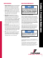
Fontaine Chassis
Operator’s Manual
© Copyright 2014 Fontaine Engineered Products 07/14
Read this manual carefully and completely before operating or
performing maintenance on your Fontaine Chassis. If you have
any questions regarding your Fontaine Chassis. Please contact
Fontaine Service at 866-382-7278.
Section 1 - Operating Instructions
Operating Instructions............................................................................................. 3
Operating Limits And Restrictions............................................................................ 4
Decal Locations....................................................................................................... 5
Landing Gear.......................................................................................................... 9
Suspension System: Axle Alignment...................................................................... 10
Anti-Lock Braking System..................................................................................... 12
Anti-Lock Braking System: Lamp Codes............................................................... 13
Coupling and Uncoupling...................................................................................... 14
Twistlock Operation............................................................................................... 17
Sliding Suspension Operation................................................................................ 18
Sliding Suspension Positioning.............................................................................. 18
Contents
Contents
Section 2 - Optional Features and Instructions
Basic Maintenance Schedule................................................................................ 19
Section 3 - Preventive Maintenance
Lubrication Notes.................................................................................................. 20
Basic Chassis Maintenance................................................................................... 20
Leaf Type Springs Care And Maintenance............................................................. 21
Wheel and Rim Care............................................................................................. 21
How To Service And Install Wheel Bearings........................................................... 22
Wheel Installation and Maintenance....................................................................... 23
Self Adjusting Slack Adjuster................................................................................. 25
Tips for Prolonged Brake Drum Life....................................................................... 26
Tire Maintenance .................................................................................................. 26
Demounting and Mounting Tires............................................................................ 28
Electrical System................................................................................................... 29
Brakes................................................................................................................... 30
Section 4 - Troubleshooting Guide
Wheels, Tires and Alignment................................................................................. 31
Landing Gear........................................................................................................ 32
Electrical System................................................................................................... 32
Fontaine Chassis Parts.......................................................................................... 33
Section 5 - Important Information
NHTSA Reporting ................................................................................................. 34
Index..................................................................................................................... 35
Maintenance Record............................................................................................. 37
2
This manual has been prepared to assist you in the
safe operation and maintenance of your FONTAINE
Chassis. It contains important information on the
proper use of your FONTAINE Chassis and the major components and optional equipment included.
WARNING
THIS SYMBOL IS USED THROUGHOUT
THIS MANUAL TO CALL ATTENTION TO
THE PROCEDURES YOU MUST FOLLOW
EXACTLY. CARELESSNESS OR FAILURE
TO FOLLOW INSTRUCTIONS MAY LEAD TO
DEATH OR SERIOUS INJURY.
CAUTION
It is important that every chassis owner and/or operator have an organized Trailer Preventive Maintenance
program (TPM). The United States Department of
Transportation requires by law that maintenance records be kept on every commercial highway vehicle.
It is to your advantage to be able to show that regularly scheduled TPM inspection checks have been
made on every piece of equipment operated.
A regular TPM program will not only assure you will
get the most usage from your chassis, but will also
assist in demonstrating that the equipment has been
properly maintained.
You can get help in setting up and operating a chassis preventive maintenance program by sending for a
“Maintenance Manual for Trailers and Containers”. Contact the Truck Trailer Manufacturers Association, 1020 Princess Street, Alexandria, Virginia
22314.
THIS SYMBOL IS USED THROUGHOUT
THIS MANUAL TO CALL ATTENTION TO
THE PROCEDURES YOU MUST FOLLOW
EXACTLY. CARELESSNESS OR FAILURE
TO FOLLOW INSTRUCTIONS MAY LEAD TO
DEATH OR SERIOUS INJURY.
Read this manual carefully. Should you
have any questions, contact a FONTAINE
factory representative immediately.
NOTE
For Warranty, Parts and
Technical Service call
THIS SYMBOL IS USED THROUGHOUT THIS
MANUAL TO CALL ATTENTION TO OPERATIONS, PROCEDURES AND INSTRUCTIONS
THAT ARE IMPORTANT FOR PROPER SERVICE. IT MAY ALSO INDICATE INFORMATION THAT CAN MAKE SERVICE QUICKER
OR EASIER.
IMPORTANT
1-205-385-0930
Section 1 - Operating Instructions
Section 1 - Operating Instructions
Operating Instructions
1-866-382-7278
This manual should be kept with the chassis at all times and should be left with the
chassis when/if it is sold.
All operator instructions are provided for assistance in
the proper operation of your chassis. Specific component operating instructions and your company’s
procedures should be consulted. These may include
DOT and employer training programs or instructions.
This manual includes safety checks the chassis operator must perform.
3
This FONTAINE chassis was designed for operation
within legal highway speed limits on reasonable road
surfaces for the type of service it was built to perform
in accordance with the following:
1. This chassis was built to carry cargo within the
limitations of two weight ratings on the identification plate. These ratings, GAWR and GVWR, are:
a. The GAWR (gross axle weight rating) is the
structural capability of the lowest rated member of the running gear components: suspensions, hub, wheels and drums, rims, bearings,
brakes, axles or tires.
b. The GVWR (gross vehicle weight rating) is
the structural capability of the chassis when
supported by the kingpin and axles with the
load uniformly distributed throughout the cargo
space, as defined by the V. I. N. plate.
2. The Concentrated load rating is the structural capability of the chassis frame for non-uniform loads
that are concentrated on the deck of the chassis
in a specified location. Contact a Fontaine Dealer
or Representative for the concentrated rating for
your chassis.
WARNING
THE PUBLISHED GVWR, GAWR, AND
CONCENTRATED LOAD RATINGS SHOULD
NEVER BE EXCEEDED.
Beginning March 1, 1998 all chassis are required by
law to have anti-lock brake systems on at least one
axle per FMVSS-121 (49CFR 571.121). A “4S-2M”
system means there are 4 sensors and 2 modulator
valves controlling the axles while a “2S-1M” system is
2 sensors and 1 modulator valve. Refer to the manufacturer of the ABS system for specific information on
the various components.
Section 1 - Operating Instructions
Operating Limits And Restrictions
NOTE
THE MAXIMUM LOAD INDICATED ON THE
IDENTIFICATION PLATE MAY OR MAY NOT
BE A LEGAL LOAD ON THE HIGHWAY YOU
PLAN TO USE.
4
NOTE
NOTE
Decals are an important part of the
chassis operation. Knowing where
decals are located and what information they convey will help in
the maintenance of the chassis, the
safe operation of the chassis and in
maintaining compliance with state
and federal regulations.
If any of these decals are missing
contact Fontaine for replacement
information. The following decals
represent the standard decals and
their locations at the time of printing / chassis manufacture.
Section 1 - Operating Instructions
Decal Locations
5
Section 1 - Operating Instructions
Decal Locations
6
Section 1 - Operating Instructions
Decal Locations
7
Section 1 - Operating Instructions
Decal Locations
ABS decal
ABS Indicator light
NOTE
NOTE
If any of these decals are missing contact
Fontaine PartSource for replacement information at 866-382-7278. In some instances decals may be updated or replaced by
other decals. The preceding decals represented the standard decals and their locations at the time of manufacture.
If any of these decals are missing
contact Fontaine Engineered Products for replacement information.
The following decals represent
the standard decals and their locations at the time of printing / chassis manufacture.
NOTE:
The decals appearing above are only a
representation of some of the decals that may
be found in this area of your Fontaine Chassis.
The decals above are not, and are not intended,
to provide a complete representation of the
decals that may be placed in this area.
8
Your Fontaine chassis is equipped with an OEM
selected landing gear designed to meet the needs
of the industry. The operational characteristics are
shown below.
Gear Speed Operation
Push 2-speed
handle in for
low-speed
operation
Extend
(CW)
Retract
(CCW)
TRAVEL DIRECTIONS:
Rotate crank clockwise to extend landing gear, and
counterclockwise to retract landing gear.
Pull 2-speed
handle out for
high-speed
operation
For low speed, extension or retraction, push crank in.
For high speed, extension or retraction, pull crank out.
CAUTION
Stow handle
when not in use
NOTE
Landing Gear Bolts . . .
Use a minimum 5/8” Grade-5 bolt on all
Landing Gear connections except on
cross pipe. On cross pipe use a minimum 5/16” Grade-5 bolt.
1. Do not over extend landing gear.
2. Never drop chassis on landing gear. Always extend landing gear until the landing
gear foot contacts the ground, then lift the
chassis approximately 1 inch before removing the tractor from the chassis.
3. Always ensure that the landing gear foot
rests on a hard surface capable of supporting the chassis and load ( hard ground,
concrete etc. ).
If necessary, place foot pads on a support
plank to prevent the landing gear from
sinking into the surface.
4.Always retract landing gear fully before
moving the chassis.
5. Always store the crank in the crank holder
after extending or retracting the landing
gear.
6. Replace all damaged or worn parts.
7. Failure to replace worn or damaged riser
nut and retracting screw assembly could
cause a failure.
Section 1 - Operating Instructions
Landing Gear
NOTE
Torque Chart . . .
5/16” Grade - 5 17 Ft Lbs Dry 13 Ft Lbs Oiled
5/8” Grade - 5 150 Ft Lbs Dry 110 Ft Lbs Oiled
9
Your Fontaine chassis is equipped with either an air
ride suspension or mechanical spring suspension.
Common suspension suppliers to Fontaine include
Hendrickson, Meritor and Hutch. Additional information including installation, service, maintenance recommendations warranty and general sales data for all
of the systems can be found on their websites. Links
to their website are shown below.
Hendrickson: www.Hendrickson-Intl.com
Meritor: www.meritor.com
Hutchens Industries: www.hutchensindustries.com
SAF Holland: www.SAFHolland.us
AXLE ALIGNMENT
SINGLE AXLE CHASSIS
1. Raise or lower the landing gear legs to position
chassis kingpin plate at design height if known
(use 49" if actual design height is unknown).
2. Remove the outer wheel assembly or the outer
tires and rims, depending on the wheel equipment.
3. Remove any parts from under the chassis that can
interrupt measuring the distance between the king
pin and the ends of the axle.
4. Attach a steel measuring tape to a hook and the
hook over the kingpin. Measure the distance “A”
and “B” from the king pin to the ends of the axle.
The difference between the “A” and “B” measurements must not exceed 1/8” (3.2mm).
A
B
Section 1 - Operating Instructions
Suspension System: Axle Alignment
10
TANDEM AXLE CHASSIS
Measuring the alignment of a tandem axle chassis
is not very different from the procedure for the single
axle chassis. The chassis must be correctly positioned before making the necessary measurements.
1. Move the chassis forward and backward over a
level floor, two or three times with the last movement forward, to permit the suspension to become correctly aligned to center the front and rear
wheel tracks.
2. Raise or lower the landing gear legs to position
chassis kingpin plate at design height if known
(use 49" if actual height is unknown).
3. Remove the outer wheel assembly or outer tires
and rims.
4. Remove any parts from under the chassis that can
interrupt measuring the distances between the
kingpin and the ends of the forward axle.
5. Attach a steel measuring tape to a hook and the
hook over the kingpin. Measure the distance “A”
and “B” from the king pin to the ends of the forward axle. The difference between the “A” and “B”
measurements must not exceed 1/8” (3.2mm).
6. Measure the distance “C” and “D” between
the front and rear axle centers. The difference
between “C” and “D” measurements must not
exceed 1/16” (1.6mm). See art below.
NOTE
The limits of 1/16” (1.6mm) and 1/8”
(3.2mm) are the industry standard
limits for correct alignment of the
axles. These small variances permitted by the standard make acquiring accurate measurements all the
more important and critical to the
proper operation of your chassis.
How to Correct the Alignment of Axles
To correct alignment measurements that are not within
the limits, inspect the suspension for worn, broken or
loose parts. Adjustment to the suspension, and the
replacement of worn or broken parts, must be made to
achieve an acceptable axle alignment.
CAUTION
Carefully follow the service instructions made available by the
suspension manufacturer when
working on this component.
Section 1 - Operating Instructions
Suspension System: Axle Alignment
NOTE: SEE HENDRICKSON PROCEDURE L579 FOR
MORE DETAILED INFORMATION.
www.Hendrickson-Intl.com
SAF Holland: www.SAFHolland.us
A
C
B
D
11
CAUTION
ABS NOTICE - CONNECTOR
WIRING CHANGE
NOTICE TO ALL TRACTOR CHASSIS OWNERS AND USERS
Federal Motor Vehicle Safety Standard No.
121, Air Brakes Systems, was amended by the
National Highway Traffic Safety Administration of
the DOT to require that truck tractors manufactured on or after March 1, 1997 provide constant power for a chassis antilock brake system
(ABS). Some manufacturers will provide this
feature before the effect date.
These tractors using a single 7-way
electrical connector will have constant
power for ABS on the center pin when
the key switch is on.
Fontaine, as well as other tractor-chassis owners and users who presently use the center
pin for auxiliary power to equipment other than
chassis ABS (for example, dome lights, backing
lights, bottom dumps, sliding undercarriages, air
ride dump valves, etc.) will be affected by this
change.
In certain uses of this constantly powered center pin connector, unexpected
or unintended activation of this equipment may be hazardous or result in
personal injury.
Meritor WABCO Easy-Stop (TM) Anti-lock Braking
System (ABS) is standard equipment on all Fontaine
chassis with GVWR less than 120,000 lbs. The system monitors wheel speed at all times and improves
vehicle stability and control by reducing wheel lock
during braking.
CAUTION
ABS information in this Operator’s
Manual was provided by Meritor
Wabco and is specific to its products. If your chassis is equipped
with another manufacturer’s AntiLock braking system, you must contact Fontaine or the manufacturer
of the braking system, for the instructions specific to that braking
system. Visit www.meritorwabco.
com for more information.
ELECTRONIC CONTROL UNIT ( ECU )
MALFUNCTION
In the event of an ECU malfunction, the ABS, in the
affected wheels, is disabled. The affected wheels
should continue to operate in a non ABS braking
mode, if the braking valve itself has not failed. The
ABS should continue to operate on the wheels unaffected by the ECU malfunction.
Section 1 - Operating Instructions
Anti-Lock Braking System
Two ABS indicator lamps (one on the dash of the
tractor and one on the side of the chassis) let the
driver know the status of the system.
BEFORE connecting your chassis to a tractor,
MAKE SURE that the constantly powered center pin WILL NOT UNINTENTIONALLY TURN
ON CHASSIS EQUIPMENT. If you have any
questions about your present wiring, or how to
rewire your vehicles, you should contact Fontaine PartSource at 1-866-382-7278.
12
ABS INDICATOR LAMP
The ABS Indicator Lamp (amber) is located on the
road side (driver side), near the rear marker lamp
(red). The lamp is identified with the letters ABS. This
lamp indicates the status of the chassis ABS.
If the ABS lamp comes ON and stays ON when you
apply the brakes to a moving vehicle, there is an ABS
malfunction. It is normal for the lamp to come ON
and go OFF to perform a bulb check, but it should
not stay ON when the vehicle is moving about 4
MPH. As with any safety system, it is important not to
ignore this indicator. If the indicator lamp indicates a
malfunction, the vehicle can be operated to complete
the trip. However, it is important to have the vehicle
serviced as soon as possible using the appropriate
maintenance manual to ensure proper braking performance and to ensure that the benefits of ABS remain
available to the driver.
ABS Indicator light
System Is Ignition Powered ( constant power)
Brakes
Released
Ignition
Fault in
System
Vehicle Speed
Indicator Lamps
(Chassis and Dash)
OFF
N.A.
N.A.
OFF
NO
Less than 4 mph
ON for 3 seconds then go OFF.
NO
Greater than 4 mph
OFF
YES
N.A.
ON
NO
Less than 4 mph
ON for 3 seconds then go OFF.
YES
N.A.
ON
NO
Less than 4 mph
ON for 3 seconds then go OFF.
NO
Greater than 4 mph
OFF
YES
N.A.
ON
ON
OFF
Applied
ON
Section 1 - Operating Instructions
Anti-Lock Braking System: Lamp Codes
Blink Codes: Blink codes are the number of times the ABS lamp blinks on and off. The number of
blinks refers to the problem area. See Meritor Wabco Maintenance And Troubleshooting Manual for
complete details.
13
Knowing how to couple and uncouple correctly is
basic to safe operation of combination vehicles.
General coupling and uncoupling steps are listed
below. Different tractors and coupling devices require
different techniques, so learn the details for coupling
and uncoupling the tractors and coupling devices you
operate.
WARNING
Incorrect coupling and uncoupling
of your chassis can result in accidents causing serious injury or
death. Not all tractors are identical. Be aware of the differences in
the vehicles you operate.
COUPLING
1. INSPECT THE TRACTOR FIFTH WHEEL
• Check for damaged or missing part. Reference
the manufacturer’s service manual for the fifth
wheel in use.
• Check to see that mounting to tractor is secure - no cracks in frame, etc.
• Be sure the fifth wheel plate is properly greased,
failure to do so may cause severe friction leading
to loss of control.
• Check if fifth wheel is in proper position for coupling (Wheel tilted down towards rear of tractor,
jaws open and safety unlocking handle in the
automatic lock position).
• If you have a sliding fifth wheel, make sure it is
locked.
• Make sure the chassis kingpin is not bent, broken
or damaged in any way.
2. INSPECT AREA AND CHOCK WHEELS
• Make sure area around vehicle is clear.
• Be sure chassis spring brakes are on.
4. BACK SLOWLY
• Back until fifth wheel touches the chassis.
• Do not impact the chassis.
5. SECURE TRACTOR
• Apply the parking brake.
• Shift the transmission into neutral.
6. CHECK CHASSIS HEIGHT
• The chassis should be low enough so that it is
raised slightly by the tractor when the tractor is
backed under it. Raise or lower the chassis as
needed. Make sure the chassis is proper height
and the kingpin and fifth wheel aligned.
CAUTION
If chassis is too high, it may not couple correctly to the tractor. If it is
too low, the kingpin may be struck
and bent or the front of the chassis may be damaged.
WARNING
Do not walk or stand between tractor and chassis. Tractor movement
can cause serious injury or death.
Section 1 - Operating Instructions
Coupling and Uncoupling
7. CONNECT AIR LINES TO CHASSIS
• Check glad hand seals and connect tractor supply
(emergency) airline to chassis supply (emergency)
gland hand.
• Check gland hand seals and tractor control (service) airline to chassis control (service) gland hand.
• Make sure airlines are supported where they cannot be hung-up or damaged while tractor is backing under chassis.
• Check that all chassis cargo is secured against
movement.
3. POSITION TRACTOR
• Put the tractor directly in front of the chassis.
• Check position, using outside mirrors, look down
both sides of the chassis.
CAUTION
Never back a tractor under a chassis
at an angle. Pushing the chassis sideways can damage the landing gear or
other structures of the chassis.
14
8. SUPPLY AIR TO CHASSIS
• From the tractor cab, push in “air supply” knob
or move tractor protection valve control from the
“emergency” to the “normal” position to supply air
to the chassis brake system.
• Wait until the air pressure is normal.
• Check brake system for crossed airlines.
• Shut engine off to hear brakes.
• Apply and release chassis brakes, listen for the
sound of chassis brakes being applied and released.
• Check the air brake system pressure gauge for
signs of major loss.
• When sure chassis brakes are working properly,
start the engine.
• Check to see that tractor air pressure is greater than
120 psi .
9. LOCK CHASSIS BRAKES
• Pull out the “air supply” knob or move the tractor
protection valve from “normal (Chassis Brakes Released)” to “emergency (Chassis Brakes Applied)”.
WARNING
Make sure the parking brake is engaged and the tractor cannot be
moved before placing any part of
your body between the tractor
and chassis. Tractor movement can
cause serious injury or death.
14. CONNECT ELECTRICAL CORD and CHECK
AIRLINES
• Plug the electrical cord into the chassis and fasten
the safety catch.
• Check both airlines and electrical line for damage.
• Make sure air and electrical lines will not be
crushed or damaged by any of the vehicles moving parts.
• Visually inspect to see that the ABS light functions
correctly when the power cord is connected. If
the light stays on or comes on during use, have
the ABS unit repaired at once.
• Back tractor slowly under chassis to avoid severely
impacting the kingpin.
15. RAISE FRONT CHASSIS SUPPORTS (LANDING GEAR)
• Use low gear range (if equipped) to begin raising
the landing gear. Once free of weight, switch to
high gear range.
• Stop when the kingpin is locked into the fifth wheel.
• Raise landing gear all the way up. 11. CHECK THAT CONNECTION IS SECURE
• Raise chassis landing gear slightly off the ground.
• After raising the landing gear fully, secure the
crank handle.
• Gently pull the tractor forward while the chassis
brakes are still locked.
• When full weight of chassis is resting on tractor,
check for clearance between rear of tractor frame
and landing gear.
10. BACK TRACTOR UNDER THE CHASSIS
• Shift into lowest reverse gear.
• Fifth wheel should be locked into kingpin at this
time.
12. SECURE VEHICLE
• Shift the transmission into neutral.
• Check that there is enough clearance between the
top of the tractor tires and the nose of the chassis.
CAUTION
• Apply parking brakes.
• Shut off engine and be sure someone else will not
move the truck while you are under it.
13. INSPECT COUPLING
• Use a flashlight if necessary.
• Make sure there is no space between upper and
lower fifth wheel. If there is space, something is
wrong! The kingpin may be on top of closed fifth
wheel jaws; chassis would come loose very easily.
Section 1 - Operating Instructions
Coupling and Uncoupling
Never drive with the landing gear
partially down; it could hang on
railroad tracks or other objects.
• Look into the back of the fifth wheel with caution.
Make sure the fifth wheel jaws have closed around
the shank of the kingpin.
• Check that the locking lever is in the “lock” position.
15
UNCOUPLING TRACTOR-CHASSIS
1. POSITION RIG
• Make sure the surface of the parking area can
support the weight of chassis.
• Have tractor lined up with chassis. (Pulling out at
an angle can damage landing gear.)
2. EASE PRESSURE ON LOCKING JAWS
• Shut off chassis air supply to lock chassis brakes.
Ease pressure on fifth wheel by backing up gently
(this will help to release the fifth wheel locking
lever).
• Put parking brakes on while tractor is pushing
against the kingpin. This will hold the rig with pressure off the locking jaws.
5. UNLOCK FIFTH WHEEL
• Raise release handle lock.
• Pull the release handle to the “open” position.
• Stay clear of the rear of the rear tractor wheels to
avoid serious injury in the event vehicle movement.
6. PULL TRACTOR PARTIALLY CLEAR
OF CHASSIS
• Pull tractor forward until fifth wheel comes out
from under chassis.
• Stop with tractor frame under chassis (Prevents
chassis from falling to ground if landing gear
should collapse or sink.)
7. SECURE TRACTOR
• Apply parking brake.
3. LOWER THE LANDING GEAR
• If chassis is empty – lower the landing gear until it
makes firm contact with the ground, turn crank in
low gear a few extra turns; this will lift some of the
weight off the tractor. (Do not lift chassis off the
fifth wheel.) This will make it easier to unlatch the
fifth wheel and easier to re-couple.
• Place transmission in neutral.
4. DISCONNECT AIRLINES AND
ELECTRICAL CABLE
• Disconnect airlines from chassis. Connect airline
gladhands to dummy couplers at back of cab or
couple them together.
• Check the area, then drive the tractor clear.
8. INSPECT CHASSIS SUPPORTS
• Make sure ground is supporting chassis.
• Make sure landing gear is not damaged.
9. PULL TRACTOR CLEAR OF CHASSIS
• Release parking brakes.
Section 1 - Operating Instructions
Coupling and Uncoupling
• Hang electrical cable with plug down to prevent
moisture from entering it.
• Make sure lines are supported so they won’t be
damaged while driving the tractor.
16
Rear Twistlock in Unlocked position
Lift lever
Rear Twistlock in locked position
Lift lever
Twist handle
Twist handle
This photo shows the rear twistlock in the
unlocked position. To lock, lift lever and turn
handle.
This photo shows the rear twistlock in the
locked position. To unlock, lift lever and turn
handle.
Front Twistlock in Unlock position
Front Twistlock in Unlock position
This photo shows the front pin in the unlocked
position. To lock, lift and push handle back to
place it in rear slot.
This photo shows the front pin in the locked
position. To unlock, lift and pull the handle to
move it to forward slot.
Front pin unlocked
Section 1 - Operating Instructions
Twistlock Operation
Front pin locked
17
Sliding Suspension Positioning
WARNING
Failure to lock a sliding suspension
can cause loss of vehicle control,
property damage, serious bodily
injury and death. Always check to
ensure that lock pins are fully engaged in the chassis frame or slider rail before use.
Pin disengaged
Operating Handle
in “OUT” position
When a chassis is equipped with a sliding suspension
follow these procedures.
1. Make sure the suspension is securely locked into
place. The suspension is locked into place when
the main body of each lock pin extends through
the holes in the rails.
Pin engaged
Operating Handle
in “IN” position
Important!! Locking Pins Must Extend Thru
Holes in the Body of the Chassis Before Moving
the Vehicle
2. Inspect the suspension carefully to ensure it is
properly positioned and the main body of each
lock pin does extend through the holes in the rails.
3. Check area around and under chassis to be clear
of obstructions or personnel.
4. Apply the chassis brakes and gently rock the
chassis backwards and forwards to make sure the
sliding suspension is secure.
NOTE
Reference the suspension manufacturer’s recommendations for more
detailed operating instructions,
cautions and warnings.
1. Set both the tractor and chassis brakes.
2. Remove stop bar and move to desired position.
3. To release the lock pins: Lift pull arm and pull until
locked in the “OUT” position. If lock pins do not
retract after pull arm is locked in the “OUT” position,
gently rock trailer with brakes applied and pins will
automatically retract.
4. Apply trailer brakes and carefully move trailer until
contacting stop bar.
5. Release pull arm to the “IN” position and visually
check all lock pins for proper engagement.
6. Locate stop bar directly behind slider.
7. Before moving the trailer, the pull arm must be in the
“IN” position, and all lock pins must extend through
the rails or beams.
8. With the chassis brakes applied, gently rock chassis
backward and forward to ensure sliding suspension is properly locked and follow proper operating
procedures before pulling chassis. The lock pin must
be checked at each stop to ensure each is locked.
Note: Locator bars are not used on a
chassis equipped with a single slider. The chassis
is equipped with stops at the front and rear extremes of the slider movement.
Section 2 - Optional Features and Instructions
Sliding Suspension Operation
18
Frequent inspection and preventative maintenance
are important in the life of any machine. Your FONTAINE chassis is no exception. Proper care and
maintenance will protect the long life of your chassis and may eliminate unnecessary repair costs and
downtime.
DAILY INTERVALS (PRE-TRIP INSPECTION)
Drain Moisture:
Drain the moisture from air reservoir daily by opening
the drain cock on underside of reservoir. Leave the
drain cock open until the moisture disappears. After
all moisture has escaped, close the drain cock or
moisture trap.
Inflate Tires:
Check tire pressure daily or every 3000 miles. Remove all objects lodged between treads or carcasses
or from between duals. Refer to the Tire Manufacturers Load/Inflation pressure settings for your applicable tire size.
Tighten Mounting Nuts:
Check that all wheel and hub mounting nuts are present and secure. If marked after torquing, insure the
torque identification mark has not moved.
Wheel-ends:
Visually inspect the hubcap and around the wheel
seal for lubrication leaks.
Adjust Brakes:
Check the travel of brake chamber push rod and
adjust brakes if necessary. Push rod travel should be
kept at a minimum of 1/2” without brakes dragging.
Pushrod travel should not exceed 2”.
Check Lights:
Open and close chassis light switches to see if lamps
respond properly. Clean all lights and warning reflectors. Make sure the ABS system is operating properly.
Check Tools & Equipment:
Check the tools, flares and other equipment to make
certain all are present and in good condition. This
inspection should become a daily habit. Minor repairs
or adjustments depend to a great extent upon the
tools and equipment carried on the chassis.
MONTHLY INTERVALS
Inspect Hose Assemblies & Gaskets:
Inspect all hose assemblies and gladhand coupling gaskets for abrasions, swelling, or other damages. Replace
as necessary.
Check Brake Linings:
Check the brake lining thickness. Brake lining should be
replaced when the lining thickness approaches the wear
line indicator built into the lining or when the thickness is
at ¼”.
Inspect Reservoir & Brake Lines:
Inspect reservoir for looseness or damage. Make
certain all connections are tight, and that brake lines are
properly supported so as not to chafe on other chassis
parts.
Check Electrical System:
Inspect lights, wiring, and coupling sockets. Secure
loose wires.
Tighten Assembly, Screws & Nuts:
Tighten all wheel hub mounting nuts, spring clips, and U
bolts.
Measure and check all tires:
Measure and check all tires for proper mating and unserviceable condition. Serviceable tires which indicate
abnormal wear should be rotated to other wheel positions. Apparent mechanical defects should be corrected.
Check Axle Alignment:
Check the axle for proper alignment. This deficiency is
the most probable cause of tire wear.
Section 3 - Preventive Maintenance
Basic Maintenance Schedule
Inspect & Clean Under Side of the Chassis:
Clean out all objects lodged in the under-construction
including the suspension area. For mechanical spring
systems, inspect springs, bushings, and hangers for
cracks or excessive wear. Check all hanger bolts, “U”
bolts and other adjustable points. For air ride systems,
check air springs, and shocks for wear or damage.
Check the suspension rubber bushings and wear washers to make certain they are in good condition.
SIX (6) MONTH INTERVAL
Check structure for cracks in welds or steel. Check
for any other structural damages. Fontaine Engineered
Products/Fontaine PartSource
should be consulted
for repair instructions.
19
1. Coupler & Kingpin: Clean all sand, grit and other
foreign matter from coupler base. With a hand
paddle, coat the machined surface of coupler
base pickup ramps and edge of coupler hook.
Place a light film of grease on the side surface of
kingpin. Lubrication Interval – every 5,000 miles
2. Cam Bearing: Lubricate sparingly with grease
gun. Excessive lubrication will force lubricant into
internal brake parts causing faulty brakes.
Lubrication Interval – every 10,000 miles
Basic Chassis Maintenance
NOTE
The information provided in this section is intended to provide suggested basic maintenance procedures.
Refer to the vendor component
supplier’s information for more detailed maintenance instructions.
3. Wheel Ends: Most Fontaine Chassis are
Equipped with Hendrickson RTR suspensions
equipped with five (5) year wheel end warranty.
The typical lubrication for these wheel ends is
Chevron Delco SF grease. If no leakage is noticed
in the first 5 years of service, no wheel end lubrication maintenance is required. Units with sight
glasses in the hubcaps with removable plugs use
mineral based Hypoid Oil S.A.E. 80/90. NOTE:
On units with oil seals, change oil and seals every
100,000 miles.
KINGPIN AND FIFTH WHEEL AREA
4. Brake Shoes: Place several drops of oil on inner
and outer end of brake shoe where anchor pins
pass through the shoe. Place bar between spider
and brake shoe, and lift the cam end of shoe off
cam. Lubricate with several drops of oil on brake
shoe roller and rotate roller to new contact point.
Lubrication Interval – every 10,000 miles
Check and inspect the fifth wheel area for cracks or
breaks and for secure attachment to the chassis. Any
welding performed in this area is to be restricted to
those welds specified by Fontaine and is to be performed in the manner prescribed by Fontaine.
5. Cam: When wheels are removed, place a light
film of grease on top and bottom surface of S
cam. CAUTION: DO NOT ALLOW GREASE TO
COME IN CONTACT WITH BRAKE LINING.
Lubrication Interval – every 10,000 miles
Inspect the kingpin for excessive wear, rough edges,
looseness, broken or chipped out areas and cracks.
Any kingpin showing such condition must be replaced
at once. Do not, under any circumstance, weld the
kingpin to compensate for wear. Once a kingpin has
been heated its physical characteristics are changed
and its subsequent performance cannot be predicted.
Contact Fontaine Engineered ProductsCustomer Service for proper replacement services.
NOTE
Section 3 - Preventive Maintenance
Lubrication Notes
Fontaine recommends that only an
authorized Fontaine dealer perform repairs in the kingpin area.
REAR IMPACT GUARDS
Your new Fontaine Chassis has been designed and
tested to meet the requirements of F.M.V.S.S. 571.223
and 571.224.
The rear bumper should be checked during regular
maintenance for cracks, bonds & etc. If repair is
needed please contact Fontaine Engineered Products
and refer to TMC Recommended Practice 732 (T).
20
The leaf springs in a heavy duty truck/chassis suspension are working, flexible components and the
main load supporting members in the assembly.
They cushion the vehicle and its load from various
road shocks and provide the necessary stability to
resist roll-over, brake and drive forces. A reasonable amount of care and maintenance is required to
provide a satisfactory service life.
SERVICE TIPS
To obtain maximum service life from a spring assembly
the following steps should be followed:
The spring stack must be tightly clamped to its spring
seat and the axle to prevent any movement between
the U-bolts. This area is a dead zone and all flexing
must take place between the U-bolts and the dead
ends of the springs. Therefore, it is important the
spring U-bolts be checked for proper tightness once
or twice during the first few months of service, until
such time as the spring leaves wear-in with usage.
Thereafter, they should be checked periodically as a
matter of normal maintenance.
3. Broken spring leaves between the U-bolts indicates
loose U-bolts. Replace broken leaves at
earliest opportunity and lubricate the U-bolt threads
before tightening.
One or more broken spring leaves near or through
the center bolt hole, indicates a loose U-bolt condition which has permitted excessive flexing in the
clamp area. Failure to keep the U-bolts tight can also
cause sheared spring center bolts, broken U-bolts, or
rounding of the axle spring seat.
A broken spring leaf adjustment to or outside the
U-bolt clamp area indicates either there has been
an over-loaded condition or the spring assembly is
nearing the end of its service life. Single and multileaf springs on trucks and chassis should be closely
inspected at regular intervals for signs of such failure.
Broken leaves in a multi-leaf pile should be replaced
immediately to prevent over-loading the remaining
leaves. Better yet, the complete spring stack should
be replaced. If just the broken leaf is replaced, other
leaves in the stack will break in a short length of time.
Springs exhibit a finite (limited) service life. Failures
can be expected from normal fatigue after a responsible service use.
In suspensions using the vari-rate springs and frame
brackets, the wear pads and main spring leaves
should be checked periodically for excessive wear.
Replacement wear pads are available for most
suspensions, and it may be necessary to install them
long before the main leaf requires replacement. Excessive wear at these load contact points eliminates
the vari-rate effect resulting in a rough ride. If these
load bearing points are left unattended, wear can
progress to the point where a complete frame hanger
replacement will be necessary. In some instances, an
occasional dab of grease at these points will greatly
reduce the fretting and wearing away of the wear
pads and main spring leaf.
1. Before placing chassis in service, torque all U-bolts
evenly to manufacturer’s recommendation. 2. Retorque at 3,000 miles and every 3 months thereafter.
4. Spring leaf failures outside U-bolt area are an indication of:
a. Repeated overload.
b. Spring assembly has completed its normal life cycle. In either case the entire spring assembly
should be replaced.
5. On vari-rate spring suspensions, periodically apply
lubricant between the spring assembly and hangers
to obtain maximum service life.
Wheel and Rim Care
Standard wheel material on your Fontaine chassis
is aluminum or steel disc wheels. Wheel nuts are
inspected and tightened to specifications at the factory and must be checked again at pre-delivery. To
maintain the correct torque on the wheels of a new
chassis the nut torque must be checked periodically.
During normal highway operation of a new chassis, this check should be made at the first 100, 500,
and 1,000 miles and every 5,000 miles thereafter.
Severe service conditions may require more tightening. Loose wheel nuts may cause shimmy, uneven
tire wear, and vibration. Elongated stud holes in the
wheels may result from loose hub nuts. Wheel and
hub nuts must be torqued to proper specifications to
provide maximum service life.
Section 3 - Preventive Maintenance
Leaf Type Springs Care And
Maintenance
21
Wheel bearing life depends on three things: (1)
Proper lubrication; (2) Cleanliness; and (3) Proper
adjustment. Chassis axle bearings are normally provided with wheel seals which require only keeping the
lubrication at the proper level. Whether installing new
bearings or servicing a chassis in the shop, here are
the steps to follow.
Remove the wheel hub and bearing cones. Clean all
the old grease from wheel hub, bearing cones, and
hub cap with kerosene or diesel fuel oil (not gasoline
and not in hot solution tank or with water-alkaline
solutions). Use a stiff fiber brush, but not a steel or
brass wire brush. Dry the parts with a clean absorbent cloth or paper. Compressed air can be used to
dry the bearing only if the air is filtered, since water
in the air line can cause rusting. Also clean and dry
the hands and tools, since grease will not adhere to
a surface wet with solvent. If bearings are not to be
used soon, pack with wheel bearing grease and wrap
in clean wax paper. Don’t lay clean bearings on floor
or dirty workbench.
INSPECT FOR DAMAGE
While the bearing is clean and free of grease, inspect
it for signs of wear or damage. Excessive wear
caused by abrasive dirt is the most common cause
for premature bearing failure. This can be recognized
by a dull appearance to the rollers and raceways;
they may feel rough or show pit marks or indentations. Flaking or spalling on the small end of the
rollers on their corresponding cup and cone rolling
surfaces is caused by improper loose adjustment.
Spalling or excessive wear at the large end of the rollers indicates an overly tight adjustment.
Fractures or fine hairline cracks across the cup or
cone may be caused by forcing a cone assembly on
an oversize spindle, or forcing a cup into warped hub
bore, or by a cocked cup or a cocked cone. Brinneling (a series of lines or indentations on the raceways
spaced to a definite pattern) indicates a driving force
has squeezed the bearing and damaged the rollers and raceways. This can be caused by improper
mounting practices or by sudden excessive shock
loads.
Be sure to check the bearing cone for wear and pits.
After the bearing is clean, hold it up so that the bearing
is between the eye and the light. Look between the
rollers so that the raceway or outer surface of the cone
can be seen. Holding the cage, rotate the cone to
check for pits over its entire outer surface.
Replace bearings if any of these conditions exist. Also
replace worn or damaged grease or oil seals. Always
replace a seal if it has been removed from the axle. Be
sure to grease the lip of the grease seal before sliding
it on the axle. Check the condition of the hub and axle
spindle, and remove any nicks or burrs which might
prevent proper seating.
The bearing cup must fit tightly in hub. This must be
a press fit. Use an arbor press to install the cup in the
hub, checking to make sure that it is square and completely bottomed. If an arbor press is not available, use
an old bearing cup as a driving tool and tap it lightly
with a hammer. Never strike the narrow section of a
cup directly with a hammer, since this can chip or crack
the case hardened surface.
ADJUSTMENT OF BEARINGS
There have been many changes in the spindle nuts
being used on chassis axles. The new designs have
changed the method required to properly adjust the
bearings. While many wheel end systems still use the
old three (3) piece system, there are inherent differences even in this system depending on the source for the
spindle nuts. Adjustment of bearings requires a full understanding of the different spindle nut systems offered
and where to find the correct adjustment procedure.
Feel free to contact Fontaine PartSource, a Fontaine
dealer or the OEM factory for help in determining the
system on your chassis.
Section 3 - Preventive Maintenance
How To Service And Install
Wheel Bearings
Corrosion or its pock-marks on the raceways and
rollers, resulting from water getting into the lubricant,
can be caused by a worn or damaged grease seal,
or by handling the bearing with moist hands, or by an
improper type of lubricant. Overheated bearings have
a blue or brown-blue discoloration, and definitely indicate that the bearing metal has been damaged. This
can be caused by dirt, lack of lubricant, excessive
friction, or over adjustment (too tight).
22
Wheel Installation and
Maintenance
Some links to popular websites pertaining to chassis
axle and suspension information including wheel end
adjustment procedures are shown below. Copy the
link into your web browser to access recommended
adjustment procedures:
Disc Wheel Mounting Instructions for 6 & 10 Stud
Hubs with BALL SEAT Mounted Disc Wheels.
Webb Wheel Company: http://www.webbwheel.com/
aftermarket/training_toolbox.html
Hendrickson International: www.Hendrickson-Intl.com
Arvin Meritor: www.Meritor.com
Stemco Bearing Adjustment Procedure:
http://www.stemco.com/wp-content/uploads/2011/12/STEMCO-BearingAdjust571-2902-WEB.pdf
Rims must be correctly assembled, using the correct
capnuts and must be correctly aligned to assure maximum service life and maximum safety.
1. All parts must be clean, free of rust, dirt or paint.
2. Position the inner wheel over the studs being careful
not to damage the threads.
3. Install inner capnuts and tighten to 50 FT. LBS. in
the sequence shown
Then tighten to full torque using the same sequence
1
Hendrickson Poster – Precision Nut System:
http://www.hendrickson-intl.com/
getattachment/501103c4-c552-4c77-98b9-bccb0786f5da/T71005-PRECISION-NUT-SYSTEMInstallation-Procedu.aspx,.pdf
Hendrickson Standard Wheel end Maintenance:
http://www.hendrickson-intl.com/CMSPages/
GetFile.aspx?guid=e492c099-b370-40b4-bb4255e20a224b8d
Hendrickson HXL3 Wheel end Maintenance:
http://www.hendrickson-intl.com/CMSPages/GetFile.
aspx?guid=12294fbf-0056-44f0-a907-40e50d76fdce
Hendrickson HXL5 Wheel end Maintenance:
http://www.hendrickson-intl.com/CMSPages/
GetFile.aspx?guid=ab72b69c-5038-4670-809d7f8579831179
Hendrickson HXL7 Wheel end Maintenance:
http://www.hendrickson-intl.com/CMSPages/GetFile.
aspx?guid=7f042c45-39ae-49ea-aa6f-4ff9b7af5771
Adjustment Info can also be found in the TMC
Recommended Practices RP618A & RP622A
3
6
5
4
2
6 stud
Thread Size
1
10
8
8
3
6
3
5
4
5
7
2
10 stud
9
Torque
Standard Capnut 3/4450-500 Ft. Lbs.
16 and 1-1/8-16
2
Section 3 - Preventive Maintenance
How To Service And Install
Wheel Bearings
1
7
CAUTION
The torque listed is for dry threads
with no lubricant. Proper capnut
torque is important. Insufficient
torque can cause stud breakage
and damage. Over torque can over
stress the studs and strip the
threads.
CAUTION
Disassembly and Repair of Any Wheel
end is a Complex as well as a Safety Related Task That Should Not be
Under Taken by An Inexperienced
Mechanic. Special Tools and Information Are Required. Refer These
Repairs to Your Fontaine Dealer.
23
5. After the first 50 to 100 miles of service the capnut torque should be retightened to 500-550 ft.
lbs.
4. Position the outer wheel over the inner capnuts being careful not to damage the threads.
5. Install the outer capnuts and tighten to 50 FT. LBS.
in the sequence shown in Step 3. Then tighten to
full torque using the same sequence.
6. Make sure the surface on the disc wheel, which
is contacted by the flange nuts is flat.
7. Disc wheel mounting surfaces should not have
more than 1-1/2 Mil. Thickness of paint. Excessive paint thickness can cause loose disc
wheels.
6. After the first 50 to 100 miles of service the capnut
torque should be rechecked.
A. Loosen the outer capnuts.
B. Check the torque of the inner capnuts in the
tightening direction.
CAUTION
C. Tighten the outer capnuts to 50 FT. LBS. in
the sequence shown if Step 5. Tighten to full
torque using the same sequence.
Before installing two piece cone
lock capnuts, lubricate the contact surfaces between the capnut
and washer with SAE30W oil. This
will minimize corrosion between
the mating surfaces. Wheel studs
on hubs of vehicles utilizing the
hub-piloted wheel system have
right-hand threads.
Disc Wheel Mounting Instructions for 8 & 10
Stud Hubs with HUB PILOTED Disc Wheels.
1. All parts must be clean, free of rust, dirt or paint.
2. Position the inner wheel over the studs being careful not to damage the threads.
3. Position the outer wheel over the studs being careful not to damage the threads.
4. Install flange nuts and tighten to 50 FT. LBS. in the
sequence shown
8
8
6
4
9
1 1
10
3
3
66
5
5
44
2
2 7
8 stud
1
8
8
1
3
6
3
6
5
4
5
4
7
2
10 stud
9
2
Section 3 - Preventive Maintenance
Wheel Installation and
Maintenance
7
Then tighten to full torque using the same sequence.
Thread Size
M-22 x 1.5
Torque
500-550 Ft. Lbs.
CAUTION
The torque listed is for dry threads
with no lubricant. Proper capnut
torque is important. Insufficient
torque can cause stud breakage
and damage. Over torque can over
stress the studs and strip the
threads.
24
OPERATIONAL CHECK
Chassis equipped with Drum Brakes utilize slack
adjusters to control the relationship of the brake lining
relative to the brake drum surface to minimize springbrake pushrod stroke and maximize braking power.
It is important to ensure the slack is properly
adjusted prior to each trip.
Functional operation of the slack adjuster can be
performed on the vehicle by:
1. Block wheels to prevent
vehicle from rolling.
2. Check that the push rod
is fully retracted; apply air
to release spring brake.
3. Manually de-adjust
brakes (turn adjustment
hex counterclockwise)
to create an excessive
clearance condition. (A
ratcheting sound will occur)
4. Make a full service brake
application, on release; allow sufficient time for
brake to fully retract. During the brake release,
observe rotation of the adjustment hex (attaching
a wrench on the hex will make this rotation easier
to see). This rotation indicates that an excessive
clearance condition has been determined by the
slack adjuster, and it is making an adjustment to
compensate. On each subsequent brake release
the amount of adjustment and pushrod travel
will be reduced until the desired clearance is
achieved.
5. Refer to the Slack Adjuster manufacturer’s literature for more detailed information and proper
pushrod stroke requirements.
NOTE
Refer to the Slack Adjuster manufacturer recommendations for
complete details on maintenance,
inspection and troubleshooting of
this component.
it may lower friction capabilities in the adjusting clutch
parts, and decrease automatic adjustment reliability.
INSPECTION
1. During normal lubrication intervals, visually inspect
slack adjuster and anchor bracket for damage.
Check that anchor bracket is tight and the control
arm is in its "Full Release" position (refer to manufacturer literature).
2. Maintaining proper brake adjustment and brake balance cannot be accomplished by the slack adjuster
alone. The condition of foundation brake components has a direct bearing on the effectiveness of
brake adjustment; therefore, periodic inspection of
these components is necessary.
a. BRAKE CHAMBERS
Check that brake chamber mounting bolts are
tight and proper alignment is maintained to avoid
interference between chamber pushrod and
chamber housing. Verify that the brake chamber pushrod length is equal on opposing brake
chambers of the same axle.
b. CAMSHAFT BUSHINGS
Optimum brake adjustment cannot be achieved
when worn bushings are used
c. WHEEL BEARING ADJUSTMENT
Accurate wheel bearing pre-load is necessary to
maintain proper alignment between the brake
drum and brake shoes.
Section 3 - Preventive Maintenance
Self Adjusting Slack Adjuster
MAINTENANCE
During normal chassis lube, adjusters should be inspected for damage. Check anchor brackets to ensure
that they are tight.
During reline, check the de-adjustment torque. Place
a torque wrench on the 7/16" adjusting hex. Turn the
torque wrench counterclockwise and check that the
clutch does not slip at a torque less than 13 Ft. Lbs. A
ratcheting sound will occur while backing off. If clutch
slips at a lesser torque, the adjuster must be replaced.
LUBRICATION
The Self-Adjusting Slack Adjuster should be lubricated in conjunction with the lubrication prescribed
for vehicle chassis. The lubrication interval should not,
however, exceed 10,000 miles or 3 months. No special grease is required, however the use of moly-disulphide loaded grease or oil is not recommended since
25
Tire Maintenance
1. Allow periodic cooling off stops when operating in
mountainous terrain but do not set brakes when
drums are extremely hot. Park on level ground, in
gear for cooling-down period.
INFLATION PRESSURE
The most critical factor in tire maintenance is proper
inflation. No tire or tube is completely impervious to
loss of air pressure. To avoid the hazards of under
inflation, lost air must be replaced.
2. If possible, avoid water pockets in road that may
drench red hot drums and cause cracking.
3. Do not favor tractor or chassis brakes at the
expense of other. This reduces braking action of
the unit and places a severe burden on the brake
components doing the work.
4. Periodically inspect valves, linings, drums, cams
and other brake parts to see that they are properly
adjusted and in good working order.
5. Replace bent or distorted brake shoes immediately.
6. Replace worn brake linings before the bolts or
rivets have a chance to score the drums.
7. Remove small stones or foreign matter that may
occasionally get inside drums.
8. Consult reputable brake lining specialists for
recommended makes and grades of lining that will
prolong drum life.
9. Make sure tractor-chassis units have an adequate
ratio of surface lining area to gross vehicle weight.
10. Do not overload.
11. Balance loads wherever possible to maintain
uniform axle-load and therefore brake-drum
distribution.
12. Use brake drums of adequate weight and
thickness for unusual or severe applications.
13. Practice safe, sensible driving habits.
Driving on any tire that does not have the correct
inflation pressure is dangerous and will cause tire
damage.
Any under inflated tire builds up excessive heat that
may result in sudden tire destruction. The correct
inflation pressures for your tires are a function of
many factors including: load, speed, road surface and
handling. Consult your tire dealer for the proper inflation pressures for your application.
Check inflation pressures on all your tires at least
once a week, including spares.
CAUTION
Failure to maintain correct inflation pressure may result in sudden
tire destruction, improper vehicle
handling, and may cause rapid and
irregular tire wear.
Therefore,
inflation pressures should be
checked weekly and always before
long distance trips.
Pressure should be checked when tires are cold,
before they have been driven over the road. The ideal
time to check tire pressures is early morning. Driving,
even for a short distance, causes tires to heat up and
air pressures to increase.
Section 3 - Preventive Maintenance
Tips for Prolonged Brake Drum Life
Never bleed air from hot tires as your tires will then be
under inflated. Make sure to check both tires in a dual
fitment. Pressures should be the same.
For optimum tire performance it is usually best to use
the tire inflation pressure recommended by the tire
manufacturer for the particular axle load. Exceeding this pressure could result in reduced traction and
tread life.
26
TIRE INSPECTION
While checking inflation pressures, it is a good time
to INSPECT YOUR TIRES. ANY TIME YOU SEE
ANY DAMAGE TO YOUR TIRES OR WHEELS/
RIMS, SEE ANY OF YOUR TIRE DEALERS AT
ONCE.
Before driving, inspect your tires, including the spare,
and check your air pressures. If your pressure check
indicates that one of your tires has lost pressure of
four pounds or more, look for signs of penetrations,
valve leakage, or wheel/rim damage that may account for air loss.
Always examine your tires for bulges, cracks, cuts
or penetrations. If any such damage is found, a Tire
dealer must inspect the tire at once. Use of a damaged tire could result in tire destruction, property
damage and personal injury.
DRIVE CAREFULLY
All tires will wear out faster when subjected to high
speeds as well as hard cornering, rapid starts, sudden stops and frequent driving on surfaces that are in
poor condition. Surfaces with potholes or rocks and
other objects can damage tires and cause vehicle
misalignment. When you drive on such surfaces, drive
on them carefully and slowly, and before driving at
normal or highway speeds, examine your tires for any
damage, such as cuts or penetrations.
DO NOT OVERLOAD
The maximum load that can be put on a truck tire is
dependent upon the speed at which the tire will be
used. Consult your Tire dealer for complete information on the allowable loads for your tires in your application. Tires that are loaded beyond their maximum
allowable loads for the particular application will build
up excessive heat that may result in sudden tire destruction, property damage and personal injury.
CAUTION
Exceeding the maximum speed for
vehicle your tires is rated can result in sudden tire destruction,
property damage and personal injury.
WHEN DRIVING AT HIGHWAY SPEEDS, CORRECT
INFLATION PRESSURE IS ESPECIALLY IMPORTANT.
However, at these speeds, even with correct inflation pressures, a road hazard, for example, is more
difficult to avoid and if contact is made, has a greater
chance of causing tire damage than at lower speed.
Moreover, driving at high speed increases the possibility of an accident as a greater distance is required
to bring your vehicle to a safe stop.
BALANCING
Under normal conditions, truck tires do not need to
be balanced. Common practice is to check tire balance if a ride complaint is made by the driver. Before
removing the tire-wheel assembly from the vehicle,
check for radial and lateral runout. Bent wheels and
rims or improper mounting can cause excessive
runouts. If balance is still required, a simple static
balance with bubble balance or a wall mounted axle
bearing and hub type gravity balance should be sufficient.
ROTATION
Tires should be rotated only when necessary. If the
tires are wearing evenly, there is no need to rotate. If
irregular wear becomes apparent or if the wear rate
on the tires is perceptively different (from axle to axle),
then the tires should be rotated in such a manner as
to alleviate the conditions.
Section 3 - Preventive Maintenance
Tire Maintenance
Do not exceed the gross axle weight ratings for any
axle on your vehicle.
DRIVE AT PROPER SPEEDS
The maximum speed at which tires can be operated
is indicated in the tire manufacturer's data book. This
speed varies for each type of tire and depends on the
type of application. Consult your Tire dealer for assistance in determining the maximum speed for your application. You should not exceed reasonable speeds
indicated by the legal limits and driving conditions.
27
STORAGE
All tires should be stored in a cool dry place indoors
so that there is no danger of water collecting inside
them. Serious problems can occur with tube-type
tires when they are mounted with water trapped
between the tire and tube. Due to pressurization, the
liquid can pass through the inner liner and into the
casing plies.
This can result in sudden tire failure. Most of the
problems of this nature have been due to improper
storage that allowed water to enter the casing. This is
a particular problem with tube-type tires because of
the difficulty in detecting water that collected between
the tire and tube. When tires are stored, they should
be stored in a cool place away from sources of heat
and ozone such as hot pipes and electric generators.
Be sure tires do not contact surfaces which could
deteriorate the rubber. TIRES EXPOSED TO THESE
SUBSTANCES COULD BE SUBJECT TO SUDDEN
FAILURE.
RECOMMENDATIONS FOR THE USE OF DYNAMOMETERS
Severe damage can result in the crown area of radial
truck tires when run on dynamometers for extended
periods. Quite often the damage is internal and not
discovered until after the vehicle has been put back in
service.
Demounting and Mounting Tires
CAUTION
DEMOUNTING, MOUNTING AND INFLATION OF TIRES SHOULD BE COMPLETED
BY A PROPERLY TRAINED, EXPERIENCED
AND EQUIPPED MECHANIC/TECHNICIAN.
BODILY HARM OR DEATH CAN OCCUR IF
CAUTION IS NOT EXERCISED DURING THIS
PROCESS.
ADDITIONAL INFORMATION
Always use a safety device when inflating. Never
stand over tire or in front of valve when inflating.
Before final inflation, check the assembly carefully for
apparent sign of weakness or irregularities.
TIRE MIXING
CAUTION
IMPROPER TIRE MIXING CAN BE DANGEROUS ON VEHICLES WITH FOUR OR MORE
WHEEL POSITIONS. RADIAL AND NON-RADIAL TIRES SHOULD NOT BE MIXED IN A
DUAL FITMENT.
Section 3 - Preventive Maintenance
Tire Maintenance
28
LIGHTS AND WIRING
The lighting system for your chassis is a heavy duty,
12-volt, 30-amp system. The 7-way receptacle is located on the front of the chassis near the glad-hands.
The jumper cable from the truck tractor plugs into the
chassis’ 7-way receptacle to complete the electrical
circuit to the chassis. The receptacle is equipped with
a hinge type cover to protect it from exposure to dirt
and water. The same light switches that control the
lights on the truck tractor control chassis lights.
Proper maintenance of the lighting system requires
periodic cleaning of lamps, and reflectors to assure
maximum visibility of the tractor and chassis. Use a
damp cloth to wipe the lenses. A dry cloth will cause
the dirt to act as an abrasive and scratch the lenses.
A daily cleaning can be worth the time invested, plus,
it’s a good safety practice. Maintenance of the lighting
and wiring system consists of an occasional inspection to see that all wiring connections are tight. Make
sure the lighting units are securely mounted, and the
wiring is not pinched or damaged. Inspect lights, couplings and sockets for their serviceability and replace
as required.
NOTE
All Fontaine chassis manufactured
after March 1, 1997 are wired to provide constant power to the chassis
anti-lock brake system (ABS) from
the CENTER PIN of the main 7-way
connector at the front of the
chassis. If you need help determining how your particular chassis is
wired, contact Fontaine Engineered
Products at 1-205-385-0930.
TURN SIGNAL and HAZARD FLASHER SYSTEM
The turn signal lever and hazard flasher are located in
the truck tractor. To operate the turn signals, the ignition switch must be in the ON position. The hazard
flasher system is operated independently of the ignition system in most cases. All turn signal lights can
be made to flash simultaneously by pulling out the
activating knob on the hazard flasher switch.
Two flasher units are used for the chassis. One unit
is used in the turn signal circuit and the other for the
hazard flasher system located in the truck tractor. The
most common problems with the turn signals and
hazard flasher system are defective flashers, burnedout bulbs, blown fuses, defective switches or faulty
wiring.
REFLECTORS
Reflectors are located on the front, sides and rear
sections of the chassis. They should be kept clean by
wiping with a damp cloth. Replace any reflectors that
are cracked or broken.
STOP, TAIL, TURN, MARKER & IDENTIFICATION
LIGHTS
To remove lens and bulb with grommet mount installations, insert a screwdriver under the lens flange and
pry lens out of the soft housing.
LICENSE LAMP
To remove license bulb from the license lamp, remove
the mounting screws and remove license lamp cover.
Follow the same instructions used for the clearance,
marker and identification lights above. Re-install cover
using the mounting screws.
Section 3 - Preventive Maintenance
Electrical System
CONSPICUITY/RETRO-REFLECTIVE TAPE
Proper maintenance of the conspicuity/retro
reflective tape system is the responsibility of
the owner/operator as outlined in DOT 49 CFR
393.11 (b). Conspicuity reflectivity requirements and vehicle coverage requirements are
contained in CFR Part 571 under FMVSS 108
Regulations.
29
To directly assist in keeping your chassis on the road
and rolling, the following troubleshooting guide has
been prepared for your convenience. You can avoid
serious delay and downtime in servicing your chassis
if the cause of the trouble can be diagnosed and corrected quickly by you.
BRAKES WILL NOT RELEASE
Probable Cause
Remedy
1. Low air Pressure
1. Check air line connections & verify
sufficient air in tank
2. Brake shoes bound up at cams
2. Lubricate brake operating parts.
3. Brake out of adjustment.
3. Adjust brakes.
4. Damaged brake assembly.
4. See your nearest Fontaine Service
Center
5. Source of air supply shut off at tractor
5. Push control valve IN
NO BRAKES OR INSUFFICIENT BRAKES
Probable Cause
Remedy
1. Low brake line pressure
1. Check air pressure gauge on tractor - Inoperative
2. Brake lines between tractor and
chassis not properly coupled
2. Properly couple brake lines
3. Reservoir drain cock open
3. Close drain cock.
SLOW BRAKE APPLICATION OR RELEASE
Probable Cause
Remedy
1. Lack of lubrication
1. Lubricate brake operating parts
2. Excessive pushrod travel in spring
brake air chamber
2. Adjust brakes
3. Restriction in hose or line
3. Replace broken hose or line
4. Defective brake valve
4. Replace brake valve
Section 4 - Troubleshooting Guide
Brakes
BRAKES GRABBING
Probable Cause
Remedy
1. Foreign material on brake lining
1. Reline brakes
2. Brakes out of adjustment
2. Adjust brakes
3. Brake drum out-of-round
3. Replace brake drum
4. Damaged brake chamber or internal 4. See your nearest Fontaine Service
assembly
Center
5. Leaky or broken hose between
relay valve and brake chamber
5. Replace or repair as required
BRAKES DRAGGING
Probable Cause
Remedy
1. Out of adjustment
1. Adjust brakes
2. Binding cam, anchor pins or chamber rod end pin
2. Lubricate and free up
3. Damaged brake assembly or brake
drum out-of-round
3. Replace. See your nearest Fontaine
Service Center
30
PULLING HARD
Probable Cause
Remedy
1. Broken or cracked spring
1. Replace complete spring
2. Uneven load distribution
2. Rearrange load for proper distribution
3. Weak spring
3. Replace complete spring
4. Axle out of alignment
4. Align axle
5. Tracking to one side or excess tire
wear
5. Align axle
WHEELS, HUBS AND TIRES
Probable Cause
Remedy
1. Tire wobble due to uneven rim
clamping
1. Torque tighten all rim clamps
2. Burnt, worn or damaged wheel bearings
2. Replace bearings
3. Bent wheel or rim
3. Replace wheel or rim
4. Bent axle
4. Replace axle
SCUFFED TIRES
Probable Cause
Remedy
1. Over and under inflation
1. Inflate to proper pressure
2. Excessive speed on turns
2. Reduce speed
TRACKING TO ONE SIDE
Probable Cause
Remedy
1. Leaf spring broken
1. Replace complete spring
2. Bent axle
2. Replace axle
3. Axles out of alignment
3. Align axles
Section 4 - Troubleshooting Guide
Wheels, Tires and Alignment
LOSS OF TIRE AIR PRESSURE
Probable Cause
Remedy
1. Puncture in tire
1. Repair or replace tire
2. Faulty valve or valve core
2. Replace valve assembly or core
UNEVEN TIRE WEAR
Probable Cause
Remedy
1. Over and under inflation
1. Inflate to proper pressure
2. Loose wheel stud nuts or clamps
2. Tighten wheel stud nuts or clamps
3. Loose or tight wheel bearing adjustment
3. Adjust bearings
4. Axle bent or out of alignment
4. Replace axle
5. Tires not properly matched
5. Match tires
6. Improper brake actuation
6. Correct brakes as required
7. Rapid stopping
7. Apply brakes slowly when
approaching stop
8. High speed driving on turns
8. Reduce speed
31
DIFFICULTY IN TURNING HANDCRANK
Probable Cause
Remedy
1. Bent crank shaft
1. Straighten or replace shaft
2. Bent cross shaft
2. Replace shaft
3. Lack of lubricant or correct lubricant
3. Lubricate in accordance with lubrication chart
4. Gears or components damaged
4. Free up or replace
5. Jackscrew nut jammed
5. Replace inner leg assembly
Electrical System
WIRING, FUSES & CIRCUIT BREAKER
Probable Cause
Remedy
1. Circuit breaker kicks off
1. Correct short. Splice or repair wiring
2. Wires burned
2. Replace wiring
3. Contact points dirty or corroded
3. Remove lamp unit and clean
4. Loss of ground at bulb
4. Repair as necessary
COMPLETE LOSS OF CHASSIS LIGHTS
Probable Cause
Remedy
1. Broken main harness
1. Repair or replace wire
2. Blown fuse or breaker
2. Replace fuse
3. Broken ground lead between tractor
and chassis
3. Check, repair or replace jumper
cable if equipped
4. Loose or corroded connection in
ground lead between tractor and
chassis
4. Repair or replace
Section 4 - Troubleshooting Guide
Landing Gear
DIM OR FLICKERING LIGHTS
Probable Cause
Remedy
1. Battery on tractor not sufficiently
charged
1. Change battery
2. Damaged wire in jumper cable
2. Repair or replace wire
3. Dirty or corroded contact blades
3. Clean contact blades
4. Loose connection
4. Repair as necessary
5. Poor ground at socket
5. Repair as necessary
32
Always insist on Fontaine parts and service.
Call 1-866-382-7278 for Fontaine service center and
dealer nearest you www.fontainepartsource.com
Section 5 - Important Information
Fontaine Chassis Parts
33
If you believe that your vehicle has a defect which
could cause a crash or could cause injury or death,
you should immediately inform the National Highway Traffic Safety Administration (NHTSA) in
addition to notifying FONTAINE ENGINEERED PRODUCTS.
If NHTSA receives similar complaints, it may open
an investigation, and if it finds that a safety defect
exists in a group of vehicles, it may order a recall and
remedy campaign. However, NHTSA cannot become
involved in any individual problems between you, your
dealer or FONTAINE ENGINEERED PRODUCTS.
To contact NHTSA you may either call the Auto
Safety Hotline toll-free at 1-800-424-9393 (366-0123
in Washington DC area) or write:
NHTSA
U.S. DEPARTMENT OF TRANSPORTATION
400 7th Street SW, (NSA-11)
Washington, DC 20590
You can also obtain other information about motor
vehicle safety from the NHTSA Hotline.
FONTAINE ENGINEERED PRODUCTS
3300 Industrial Parkway
Section 5 - Important Information
NHTSA Reporting
Jasper, AL 35501-9243
205-385-0930
www.fontainetrailer.com
34
A
M
ABS NOTICE - Connector Wiring Change.......... 12
Maintenance
Anti-Lock Braking System.................................. 12
Daily Intervals and Pre-Trip............................... 19
Anti-Lock Braking System: Lamp Codes............ 13
Monthly Intervals.............................................. 19
Axle Alignment.................................................... 10
Six Month Intervals........................................... 19
B
Maintenance Record.......................................... 37
Basic Chassis Maintenance................................ 20
N
Basic Maintenance Schedule.............................. 19
NHTSA Reporting............................................... 34
Brake Drum........................................................ 26
Brakes................................................................ 30
C
Conspicuity........................................................ 29
Contents.............................................................. 2
Coupling............................................................. 14
Coupling and Uncoupling................................... 14
D
Decal Locations.................................................... 5
Demounting and Mounting Tires......................... 28
O
Operating Instructions.......................................... 3
Operating Limits And Restrictions......................... 4
R
Reflective Tape................................................... 29
Reflectors........................................................... 29
Reporting Safety Defects.................................... 34
S
Self Adjusting Slack Adjuster.............................. 25
Slack Adjuster.................................................... 25
E
Sliding Suspension Operation............................. 18
Electrical System.......................................... 29, 32
Sliding Suspension Positioning........................... 18
F
Fifth Wheel......................................................... 14
Fontaine Chassis Parts....................................... 33
Fontaine PartSource........................................... 33
Section 5 - Important Information
Index
Suspension System Axle Alignment
How to Correct the Alignment of Axles............. 11
Suspension System: Axle Alignment................... 10
Single Axle Chassis.......................................... 10
Tandem Axle Chassis....................................... 11
H
Hazard Flasher System....................................... 29
Hub/Wheel Installation and Maintenance............ 23
L
Landing Gear.................................................. 9, 32
Leaf Type Springs Care And Maintenance.......... 21
License Lamp..................................................... 29
Lights 29
Lights and Wiring................................................ 29
Lubrication Notes............................................... 20
35
T
Tire Maintenance................................................ 26
Troubleshooting
Brakes............................................................. 30
Electrical System.............................................. 32
Landing Gear................................................... 32
Wheels, Tires and Alignment............................ 31
Turn Signal......................................................... 29
Twistlock Operation............................................ 17
U
Uncoupling......................................................... 16
W
Wheel and Rim Care........................................... 21
Wheel Bearings.................................................. 22
Wheel Installation and Maintenance.................... 23
Wheels, Tires and Alignment............................... 31
Section 5 - Important Information
Index
FONTAINE ENGINEERED PRODUCTS
3300 Industrial Parkway
Jasper, AL 35501-9243
205-385-0930
www.fontainetrailer.com
36
Date
Maintenance Performed
Section 5 - Important Information
Maintenance Record
37
Date
Maintenance Performed
Section 5 - Important Information
Maintenance Record
38