1
SD-22-3250
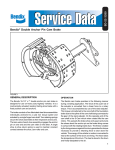
Bendix® BEPA (Ford) 15" x 4" Cam Brake
FIGURE 1
GENERAL DESCRIPTION
The Bendix® BEPA (Ford) 15" x 4" cam brake is designed
for use on heavy duty highway vehicles. It is a mechanically
actuated, leading/trailing shoe brake with a fixed position
cam and anchor.
The brake consists of two fabricated steel shoe assemblies
anchored to a cast iron torque spider and actuated by a
single forged S-cam shaft. Two retaining springs secure
the shoe assemblies to the anchor pin. The twin webs of
each shoe assembly are keyed to the anchor pin on one
end and the cam roller on the other. A single shoe to shoe
return spring is used to maintain constant contact between
the shoe, cam roller and cam.
OPERATION
The Bendix® cam brake operates in the following manner
during a braking application. The force of the push rod of
the actuator is converted from a linear force to a rotary
torque. This is accomplished by use of the slack adjuster.
This torque is transferred to the cam shaft of the foundation
brake due to the spline of the cam shaft being connected to
the gear of the slack adjuster. On the opposite end of the
cam shaft is the S-cam which when rotated lifts the cam
rollers. This spreads the brake shoe ends apart equally and
pivots the shoes about the anchor pin so the brake lining
comes in contact with the rotating brake drum. The friction
created by the lining pressure against the drum generates
the torque necessary to provide a retarding force to slow
down the vehicle. The energy of the vehicle in motion is
converted to heat at the surface of the drum and lining.
This heat raises the temperature of the drum. The heat is
stored in the drum, and finally dissipated to the air.
1
22
3
23
5
21
2
4
12
6
20
13
7
8
15
24
9
19
10
11
9
8
18
14
18
13
16
26
25
17
FIGURE 2 - BENDIX® BEPA (FORD) 15" X 4" CAM BRAKE
Key No.
1
2
3
4
5
6
7
8
9
10
11
12
13
2
Description
Qty.
Snap ring
1
Spacer washers
# +reqd.
Yoke pin
1
Slack adjuster
1
Yoke
1
Cotter pin
1
Washer
1
Grease seal
2
Bushing
2
Cap screw
4
Lock washer
4
Chamber bracket and cam tube
1
Brake shoe assembly
2
Key No.
14
15
16
17
18
19
20
21
22
23
24
25
26
Description
Cam roller assembly
Anchor pin
S-Cam shaft
Shoe return spring
Anchor spring
Spider
Dust shield
Rubber inspection plug
Cap Nut
Star Washer
Actuator
Mounting Nuts
Washers
Qty.
2
1
1
1
2
1
2
2
6
6
1
2
2
PREVENTIVE MAINTENANCE
Important: Review the warranty policy before performing
any intrusive maintenance procedures. An extended
warranty may be voided if intrusive maintenance is
performed during this period.
Because no two vehicles operate under identical conditions,
maintenance intervals will vary. Experience is a valuable
guide in determining the best maintenance interval for a
vehicle.
1. BRAKE LUBRICATION
Grease camshaft bracket with vehicle manufacturer’s
recommended chassis lube. Lube once every six
months or at each chassis lubrication.
2. BRAKE RELINE
The life of the brake lining is dependent on many factors
such as the material of the lining, type of operation
the vehicle is used for, and the driver of the vehicle.
If driving conditions require frequent braking, lining
replacement will be required more often. Reline when
lining thickness at center of shoe is 5/16". Refer to
section “Reline Procedure”.
WARNING! PLEASE READ AND FOLLOW
THESE INSTRUCTIONS TO AVOID PERSONAL
INJURY OR DEATH:
When working on or around a vehicle, the following
general precautions should be observed at all times.
1. Park the vehicle on a level surface, apply the parking
brakes, and always block the wheels. Always wear
safety glasses.
2. Stop the engine and remove ignition key when
working under or around the vehicle. When working
in the engine compartment, the engine should be
shut off and the ignition key should be removed.
Where circumstances require that the engine be
in operation, EXTREME CAUTION should be used
to prevent personal injury resulting from contact
with moving, rotating, leaking, heated or electrically
charged components.
3. Do not attempt to install, remove, disassemble
or assemble a component until you have read
and thoroughly understand the recommended
procedures. Use only the proper tools and observe
all precautions pertaining to use of those tools.
4. If the work is being performed on the vehicle’s
air brake system, or any auxiliary pressurized air
systems, make certain to drain the air pressure
from all reservoirs before beginning ANY work
on the vehicle. If the vehicle is equipped with an
AD-IS® air dryer system or a dryer reservoir module,
be sure to drain the purge reservoir.
5. Following the vehicle manufacturer’s recommended
procedures, deactivate the electrical system in a
manner that safely removes all electrical power
from the vehicle.
6. Never exceed manufacturer’s recommended
pressures.
7. Never connect or disconnect a hose or line
containing pressure; it may whip. Never remove
a component or plug unless you are certain all
system pressure has been depleted.
8. Use only genuine Bendix® replacement parts,
components and kits. Replacement hardware,
tubing, hose, fittings, etc. must be of equivalent
size, type and strength as original equipment and
be designed specifically for such applications and
systems.
9. Components with stripped threads or damaged
parts should be replaced rather than repaired. Do
not attempt repairs requiring machining or welding
unless specifically stated and approved by the
vehicle and component manufacturer.
10. Prior to returning the vehicle to service, make
certain all components and systems are restored
to their proper operating condition.
11. For vehicles with Antilock Traction Control (ATC),
the ATC function must be disabled (ATC indicator
lamp should be ON) prior to performing any vehicle
maintenance where one or more wheels on a drive
axle are lifted off the ground and moving.
PREPARATION
1. Park vehicle on a level surface and prevent movement
by means other than the brakes.
2. If equipped with spring brakes, cage the spring on all
axles to be worked on.
3. Drain air from all reservoirs.
4. Raise the axle, to be worked on until the tires clear the
ground.
5. Turn the slack adjuster adjusting screw in the opposite
direction used to adjust the brakes until the cam rollers
return to the start position on the S-cam.
6. Remove wheels and drums using the procedures
specified in the vehicle maintenance manual.
FIGURE 3 - REMOVING CAM ROLLERS
3
FIGURE 4 - REMOVING SHOE RETURN SPRING
FIGURE 6 - REMOVING SLACK ADJUSTER
FIGURE 7 - REMOVING ACTUATOR BRACKET
FIGURE 5 - REMOVING SHOES
DISASSEMBLY (See Figure 2)
1. Insert a sturdy lever between one of the shoes and
the cam shaft housing. Pry shoe away from cam roller
until pin and roller assembly can be removed. Repeat
on opposite shoe. (See Figure 3) (If cam rollers or pins
show signs of wear, galling, pitting, cracks; discard and
replace with new.)
2. Remove shoe return spring and discard. Force
shoes towards the S-cam to relieve spring tension.
(Figure 4)
4
3. Remove shoes. Lift one of the shoes off anchor pin and
lower both shoes to the floor. (See Figure 5)
4. Remove the two shoe retainer springs and discard.
NOTE: If only replacing the brake shoes, no further
disassembly is required. Reverse Steps 1 thru 4. NOTE:
Always install new springs.
5. Remove the anchor pin by sliding it out of the spider.
6. Remove the cotter pin from the yoke of the actuator.
Remove yoke pin so the slack arm is free of the yoke.
Remove the two nuts and washers that secure the
actuator to the bracket and remove the actuator.
7. Remove snap ring and washer from splined end of
cam shaft. Remove slack adjuster from cam shaft. (A
puller may be required.) Remove spacers and the thick
washer from cam shaft. (See Figure 6)
8. Remove cam shaft from actuator bracket and cam
tube.
9. Mark and remove the dust shields from the spider
by removing the six cap screws using a 3/8" socket.
Do not remove unless there is apparent damage
(See Figure 7).
10. Remove the actuator bracket and cam tube from
the spider by removing the four cap screws and
lockwashers using a 3/4" socket.
11. Remove and discard the two cam shaft grease seals.
One at each end of the cam tube.
12. Remove and discard the two cam shaft bushings
located in the same area as the seals in Step 11. Use a
tool of proper diameter and length to drive the bushings
out from the backside. NOTE: Prior to removal see the
“Inspection of Parts” section, Step 1B.
13. To facilitate assembly, note or mark the relationship
of the spider to the axle (driver or curb side) and the
orientation on the axle flange. Remove the spider from
the axle flange by removing the five bolts, nuts, and
lockwashers and the nuts and lockwashers from the
three studs. NOTE: If the spider is to be reused and
there is damage to any of the three studs, they may be
pressed out of the spider and replaced with grade 8,
5/8" bolts.
CLEANING OF PARTS
After disassembling the foundation brake, wash the metallic
components in mineral spirits and wipe dry. Be careful not
to get any foreign material, especially grease on the brake
shoes or interior of the brake drum. Use a wire brush to
remove heavy contamination from the spider and outside
of the brake drum.
INSPECTION OF PARTS
1. ACTUATOR BRACKET AND CAM TUBE
A. Check assembly for bent actuator bracket and
broken or cracked cam tube welds.
B. Inspect cam shaft bushing for signs of wear. Bearing
surfaces should be smooth and free of any pitting or
fractures. Insert cam shaft and measure looseness
at both ends with a dial indicator. If more than .020"
movement is noted, replace bushings and/or cam
shaft. NOTE: If it is determined that a bushing
requires replacement, both cam shaft bushings
should be replaced.
2. CAM SHAFT
A. Inspect cam shaft spline for cracks and excessive
deformation. Replace as necessary.
B. Inspect the cam shaft bearing journals for wear or
corrosion. If the shaft shows wear or roughness that
is visible or roughness that can be detected by feel,
it must be replaced.
C. Inspect cam head for cracks, and its roller surfaces
for flat spots, brinneling, or ridges. Note unusual
wear patterns which may indicate an out-of-square
condition. Replace if any of these conditions
exist.
3. SPIDER
A. Inspect for cracked or broken surfaces on the
spider at the cam, anchor pin, and mounting bolt
holes. Replace any spider with visible damage. Do
not attempt to weld or repair. Check fit of anchor
pin in torque spider. Radial clearance in excess of
.010" indicates excessive wear. Replace anchor pin
and/or torque spider.
4. ROLLERS AND PINS
A. Inspect rollers and pins for flat spots, galling, broken
or cracked surfaces. Replace as necessary.
5. ANCHOR PIN
A. Inspect anchor pin for worn, broken or cracked
surfaces. Replace as necessary.
6. SHOES AND LINING
A. Check shoes for bent shoe webs, cracks in shoe
table welds or webs, and elongated rivet holes.
Replace shoes if any of these conditions exist.
B. Measure the shoe span by loosely installing the
anchor pin and cam roller in the appropriate ends of
the shoe web. If the distance from center of anchor
pin to center of cam roller exceeds 11.78" replace
shoe.
C. Check linings. Replace when any of the following
conditions exist:
1. Lining thickness at thinnest point is 1/4" or
less.
2. Linings are cracked or worn in an unusual or
odd pattern, i.e., lining wear tapered from side
to side across shoe table. Unusual wear patterns
can indicate damage to foundation brake parts.
3. Rivet holes are elongated in lining or shoes.
4. Lining is oil soaked.
5. Linings can be moved by hand, i.e.; loose
rivets.
5
7. BRAKE DRUMS
A. Inspect drums for cracks, heat checking, glazing,
grooving, severe out-of-round condition or bell
mouthing (must not exceed .025 T.I.R.). Replace
any cracked drums. It is recommended that drums
be turned at reline to prevent hot spotting and
achieve quicker, more complete burnishing of the
new lining.
B. Measure the drum I.D. to be sure the maximum limit
allowed (stamped on drum) has not been exceeded,
due to wear or machining.
8. MANUAL SLACK ADJUSTER
A. Check for cracks in the body and arm of the slack
adjuster.
B. Check for spline wear. The amount of backlash in
the slack adjuster to camshaft should be no more
than .094" measured 6" from centerline of the cam
shaft (See Figure 8).
.094”
6”
CAUTION: If the vehicle is equipped with spring
brakes, refer to manufacturer’s instructions. High
spring load, if not handled properly, may result in
serious injury or death may result.
ASSEMBLY (SEE FIGURE 2)
1. Install the spider onto the axle flange using the five
bolts, three 5/8" studs, lockwashers and nuts. Be sure
spider is properly oriented as noted during disassembly.
Tighten mounting bolts to vehicle manufacturer’s
specifications.
2. If cam shaft bushings were removed, replace with
new bushings. Drive into place using Owatonna 630-7
piloted driver or similar tool, taking care not to damage
or distort the I.D. of the bushings. NOTE: Bushings are
located at each end of cam shaft tube.
3. Install new cam shaft grease seals in the end of the
cam tube and chamber bracket. Use Owatonna 630-7
piloted driver or similar tool to install grease seals.
CAUTION: The lip of the grease seals must be installed
correctly to prevent possible damage. The lip of the seal
that is installed in the cam end must enter the opening
first. The lip of the seal that is installed in the opposite
end of the cam tube must enter last (See Figure 9).
NOTE: BOTH LIP SEALS POINT THE SAME DIRECTION LIP
TOWARD SLACK ADJUSTER
FIGURE 8 - CHECKING SLACK ADJUSTER BACKLASH
C. Check ability to rotate the adjusting nut at least
one complete revolution in each direction. Force
required to rotate the adjusting nut should not
exceed 15 ft. lbs. NOTE: If any of the above
conditions are found, replace the slack adjuster.
Do not attempt to repair.
9. AUTOMATIC SLACK ADJUSTERS
A. Consult manufacturer’s service information. (For
information on Bendix Automatic Slack Adjusters,
see Service Data sheet SD-05-1200, formerly
SD-05-1).
10. ACTUATORS
A. Check for cracked housing, loose mounting
studs.
B. Check for damage to the push rod, and push rod
boot (if so equipped).
C. Check for broken push rod return spring.
D. Check for excessive wear on yoke, yoke pin, and
slack adjuster yoke pin hole or bushing. There
should be no more than .031 combined free play
in these components.
6
LIP SEAL
SLACK ADJUSTER END
CAM END
LIP SEAL
ACTUATOR BRACKET
AND CAM TUBE
FIGURE 9 - SEAL INSTALLATION
4. Install the actuator bracket and cam tube onto the
spider using four cap screws and lockwashers. Torque
to 70-80 ft. lbs. Secure the actuator to the bracket
using the two nuts and washers. Torque to vehicle
manufacturer’s specification.
5. If removed, reinstall the dust shields. Tighten the six cap
screws and lockwashers to 90-110 in. lbs. torque.
6. Coat cam shaft journals with light film of chassis lube.
Do not coat “S”-cam head. Install the cam shaft into
the cam tube. Be careful not to damage the grease
seals.
7. Install the thick cam shaft flat washer, the slack adjuster,
spacers, washer, and a new snap ring in that sequence
onto the splined end of the cam shaft. Adjust end play
of the cam shaft to between .005" and .045" by using
the appropriate number of spacer washers. Make sure
the snap ring is seated into the groove at the end of the
splined camshaft.
8. Install the anchor pin into the spider. Center the anchor
pin in the spider so it protrudes equally from each
side.
9. Install new brake shoe retaining springs. Engage hook
ends of the two springs into each of the tabs of the two
brake shoes.
10. Place the top shoe onto the spider by engaging the
open slots on the end with the retaining springs onto the
anchor pin. Place opposite end of the shoe against the
S-cam. Swing the opposite shoe, with springs attached,
back until slots in the shoe engage the anchor pin, then
swing shoe toward the S-cam. Spring tension will hold
the shoes in this position.
11. Place the hook of the brake shoe return spring onto the
return spring pins on one shoe. Hold shoes against the
S-cam and connect the other hook of the brake shoe
return spring over the return spring pin of the other
shoe.
12. Insert a sturdy bar between the end of one of the brake
shoes and the spider housing at the S-cam end of the
shoe. Pry down until the brake shoe roller and pin can
be installed between the S-cam and the slots in the end
of the brake shoe. Repeat the same procedure on the
other shoe.
13. Adjust the slack adjuster until the yoke pin can be
installed through the proper hole in the arm. Install a
new cotter pin to retain. Make sure the cam rollers are
in the lowest position on the cam.
14. Lubricate the cam shaft bushings by filling the cam shaft
tube with chassis lube through the zerk fitting provided.
Fill until grease is forced out in the area of the slack
adjuster. Grease should not appear at the cam head
end. If it does, the new seal has not been properly
installed, or the old seals should be replaced.
15. Reinstall brake drums and wheels. Torque and adjust
to manufacturer’s specifications.
16. Spin the wheel slowly and adjust the slack adjuster
until wheel will no longer turn. Back off slack adjuster
just enough for wheel to spin freely. Be sure to adjust
brakes equally on each axle.
17. Apply and release brakes and observe slack adjusters.
Both slacks on each axle should respond rapidly and
in unison during application and release.
18. Drive vehicle at a low speed in a safe area and check
for brake effectiveness prior to putting back into service.
7
8
BW1458 © 2000 Bendix Commercial Vehicle Systems LLC. All rights reserved. 5/2009 Printed in U.S.A.