1
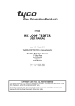
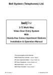
Bell
System
Wiring for DDA Extended Halo Systems
(Telephones) Ltd
DDA-EXT-1/VR(S)
Flats
Telephone Models:
801 801S 801PS
500D 500PD
Z
T
Door Panel
Phone
O
R
Call
Button
I
Z
T
DDA
Interface
PCB
O
Electrical Cupboard
R
H
C
+
-
+
-
LOCK
These 2
Connections
must be
doubled up
340C
Power Supply
C H R O T
61
Speech
Unit
Fail Secure
+ -
203, 204
Lock Release
Call
Button
www.bellsystem.co.uk
PD-176 Issue 1
Installation of Door Entry Systems
Important Safety Information
The Power Supply Unit must be placed in a protected indoor environment such as an
electrical cupboard, close to a 240V AC electrical supply and located close to the entrance. It
must be wall-mounted onto plasterboard, wood or a similar non-conductive material.
Connections to the 240V AC mains supply must be carried out by a qualified electrician or
similar competent person, and made in accordance with accepted safety practices. A twopole switch ( as provided by a Consumer Unit or Switch-Fuse) must be included to isolate
both Live and Neutral during Installation or Maintenance . The transformer is protected by
fuses; always replace these with the correct type and rating.
Use only mains cable to BS6004 or equivalent, within the following specified limits:
Conductor Diameter:
Min. 1.0mm (0.8mm2)
Max. 2.25mm (4mm2)
Cable Diameter:
Min. 4.0mm
Max. 8.0mm
The Door Entry Telephone is designed to be wall-mounted in a convenient indoor location.
The Entrance panel, containing the speech unit and DDA interface, is available with either a surface or
flush-mounting back box. Normally this would be mounted on an outside wall near the front door, and if
possible in a sheltered location.
The Model 203 Electric Lock Release is designed for use on an inward opening door fitted with a surface
night-latch type lock. This should be installed with a small amount of play on the door as operation will be
impaired if too tight.
Cable requirements: For optimum speech clarity, it is strongly recommended that this system is installed
using twisted-pair telephone cable (eg type CW1308), unless otherwise stated. Use one of the pairs for the
R & O connections between the speech unit and the telephone.
Speech adjustment: The speech unit has two controls at the rear for adjustment of speech levels:
Volume A:
Speech level at the Entrance Panel
Volume B:
Speech level at the Telephone
If feedback is experienced (a howl or whistle) turn both controls to 'off' and then slowly adjust each up in turn
until a satisfactory level of speech is attained.
Troubleshooting: No speech/ insufficient speech: Adjust the volume levels as above then establish correct
operation of the Speech Unit and telephone by disconnecting the telephone and re-connecting with a short
length of cable (R O T only).