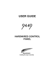
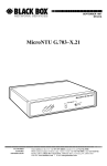
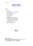
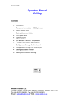
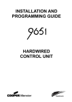
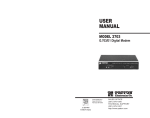
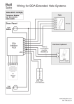
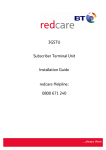
1
Locator Marker
NVM
ST1
ST2
ST3
ST4
Inputs
DC power
supply
Output
Micro
ST+
ST+
12V
0V
o/p
WARNING see
User Manual
Telephone line
connector block
under cover
Cover
Cover fixing
screws
Figure 2. 8440 PCB and Connectors.
The unit provides:
• Four separate input terminals (ST 1 to 4)
connected internally to the +12V supply by a 10ký
resistor.
• DC power input (+12V and 0V).
• One programmable transistorised output rated at
+12V 170mA. This output is normally programmed
to activate when the telephone line fails.
9056
Figure 3 shows the layout of the 9056 pcb.
Rear of plug-on
connectors (SELV)
Reset Pins
Test Pins
Locator Marker
Transmission LED
1
ST1
ST2
ST3
ST4
ST5
ST6
ST7
Spare input channel 8
DC power supply in
NVM
Micro
ST8
ST+
ST+
ST+
ST+
12V
0V
10kOhms
Line Monitor
Selector
WARNING see
User Manual
Telephone line
connector block
under cover
DC power
supply
1
Inputs
NVM
Micro
ST8
ST+
ST+
ST+
ST+
12V
0V
0V
WARNING see
User Manual
Telephone line
connector block
under cover
NO C NC NO C NC
O/P2
O/P1
Outputs
Cover
Cover fixing
screws
Figure 1. 8400 PCB and Connectors.
The unit provides:
• Eight separate input terminals (ST 1 to 8).
• Four positive reference terminals (ST+). Each
terminal is connected internally to the +12V supply
by a 10ký resistor.
• DC power input (+12V and 0V).
• Two programmable relay outputs. Each relay
provides voltage free Normally Open (NO),
Common (C), and Normally Closed (NC) contacts
rated at 24V 1A.
8440
Figure 2 shows the layout of the 8440 pcb.
840i/90001
9600/9610
9100
ATG 6000
Figure 4. Orientation of 9056
Make sure that the sockets on the communicator
are correctly aligned with the pins on the host pcb.
Take care not to damage the host or
communicator.
Wiring 8400 and 8440
1. Connect power 0V to the communicator 0V
terminal (see Figures 1, 2, 3). Do not connect
+12V power supply at this stage.
2. Connect the triggering signals to the terminals
marked ST1 to ST8 (ST4 on the 8440). Figure 5
shows examples of how to wire the inputs for the
8400 and 8440.
0V
Rear of plug-on
connectors)
808/816
Normally open contacts = +ve applied
Normally closed
contacts = +ve removed
+12V supply
Cover
Transmission LED
ST1
ST2
ST3
ST4
ST5
ST6
ST7
9800
ON
OFF
Test Pins Locator Marker
other manufacturer’s) alarm control panel or a locked
room or other enclosure.
Caution: Before starting installation remove all power
(mains and battery) from the host alarm panel.
1. Unpack the unit and remove the NVM chip (if
fitted).
2. Program the NVM chip using a 7200/7300 NVM
programmer. (Alternatively, obtain a preprogrammed chip from the central station.)
3. Fit the programmed NVM chip into the socket on
the communicator’s pcb. Make sure that the
location marker on the chip aligns with pin 1 (see
Figures 1, 2 and 3).
4. 8400, 8440: Mount the unit on the flat underside of
the control panel case using adhesive pads.
9056: Plug the communicator onto the two sets of
pins on the host main pcb. Figure 4 shows the
location of the 9056 within various hosts.
Test Pins
Transmission LED
1
Reset Pins
Reset Pins
NO C NC NO C NC
Introduction
The 8400, 8440 and 9056 Digital Communicators are
auto dialling modems that can communicate with alarm
receiving equipment using the Scancom Fast Format. All
communicators are available in two versions. The -00
versions are designed for dedicated telephone lines that
do not connect to any other equipment. The -01
versions should be used for telephone lines that have
other equipment (for example, fax or answer machines)
connected in series.
Each communicator stores its operating program in a
removable Non Volatile Memory (NVM) chip. The
communicators are programmed by removing the NVM
chip and inserting it into a 7200/7300 NVM
programmer. Once the program has been loaded the
from the 7200/7300, the NVM chip is inserted back into
the communicator.
The 8400 and 8440 are designed for use by any alarm
control panel. The 9056 is designed to plug on to
Scantronic panels, or any other manufacturer’s panel
that provides the Scantronic standard plug-on
connectors.
Application
The 8400, 8440 and 9056 Digital Communicators are
suitable for connection to the following types of
telephone line:
a) Direct exchange lines (PSTN) supporting DTMF
(tone) or Loop Disconnect (pulse) dialling.
b) PABX exchanges with or without secondary
proceed indication.
c) RBS (Relevant Branch Systems) - Please refer to
BS 6789 Section 6.1 Clause 2.4.
THE 8400, 8440 AND 9056 DIGITAL COMMUNICATORS
ARE NOT SUITABLE FOR CONNECTION AS
EXTENSIONS TO A PAYPHONE OR TO 1+1 CARRIER
SYSTEMS.
Maintenance
There are no user serviceable parts inside the 8400,
8440 and 9056 Digital Communicators. The user must
not attempt to gain access to the units.
Compatible PABXs
The 8400, 8440 and 9056 Digital Communicators may
be used with compatible PABXs. Correct operation in all
circumstances is not guaranteed, refer any difficulty to
the supplier.
Description
8400
Figure 1. shows the layout of the 8400 printed circuit
board (pcb).
Cover fixing
screws
Figure 3. 9056 PCB and Connectors.
The 9056 is 80mm wide by 25m high by 170m long
and weighs 180 gms. The unit provides:
• Two plug on connectors for input channels 1 to 8
from the host alarm control panel.
• One screw terminal for input channel 8.
• DC output (+12V and 0V). These terminals provide
+12V and 0V dc reference points for the spare
channel 8 input.
• Line monitor selector pins. by placing a jumper
over the correct pair of these pins you can enable
or disable the Line Monitoring function.
All Communicators
All three communicators provide:
• A red transmission LED that glows while the
communicator makes a call.
• Telephone Line Connector under the protective
plastic cover.
• Reset pins to allow the installer to end a call and
reset any output programmed as latch.
• Test pins to allow the installer to start a test
transmission by shorting them together with a
screwdriver.
Installation
The 8400, 8400 and 9056 may only be installed by a
professional installer.
The 8400, 8440 and 9056 are approved as host
independent modems and as such must be mounted
inside another (host) unit in such a way as to be
inaccessible without the use of a tool. For example, the
communicators may be fitted in a Scantronic (or any
ST1
ST2
ST3
ST4
ST5
ST6
ST7
ST8
ST+
ST+
ST+
ST+
12V
0V
Figure 5. Example Input Connections
Connect the outputs as necessary. These are
marked NC, C and NO on the 8400, and O/P on the
8440.
Connecting to the Telephone Network
Warning: Direct connection to or interconnection via
other apparatus to terminals contained within the
plastic enclosure marked “Safety Warning see User
Manual” can produce hazardous conditions on the
telephone network. Always seek advice from a
competent telephone engineer if in any doubt regarding
connection to these terminals.
Connections contained within the plastic enclosure do
not provide isolation sufficient to satisfy the
requirements of BS6301. All apparatus connected to
these terminals should be approved to BS6301 or have
previously been evaluated against British
Telecommunications PLC Technical Guides 2 or 26 and
given permission to attach; other usage will invalidate
any approval given.
A professional installer must connect the
communicator to the PSTN.
The person responsible for connecting the
communicator a PABX is as follows:
a) If the wiring is owned by British Telecom PLC:
British Telecom.
b) If the wiring is not owned by British Telecom,
either:
• British Telecom.
• The authorised maintainer.
• A professional installer after 14 days written
notice to the authorised maintainer.
To connect a communicator:
1. Undo the two screws on the plastic cover (marked
“Safety Warning see User Manual”) and remove
the cover.
3.
P.T.O
2.
3.
Use three core cable type 1/05 CW1308. Strip back
5mm on each core.
Connect the two cores to terminals A and B on the
telephone connector of the communicator.
Connect the cable from the A and B terminals to
the corresponding terminals on the BT master
socket.
Parallel Connection
A1 B1 C B A
1/05 Cw1308
5
2
3
NTE 5
(If 'C' leg required)
Extension Telephone
Socket
BT Master Socket
Series Connection
A1 B1 C B A
1/05 Cw1308
5
2
3
NTE 5B
(If 'C' leg required)
Extension Telephone
Socket
BT Master Socket
Figure 6. Connection to the Telephone Network
4) If other apparatus (for example a telephone)
shares the telephone line with a 8400 -01, 8440 01 or 9056 -01, connect the main apparatus to the
connection marked A1 and B1 on the
communicator. The communicators will introduce
a voltage drop of 100mV at a line current of 40mA.
Caution: Do not connect more than one such series
apparatus between a main apparatus (for example a
telephone) and the PSTN.
5) Feed the cables through the entries in the plastic
enclosures.
A1
B1
A
B
Figure 7. Telephone Cable Entry
Note: Early models of the 8400/8440/9056 have an
Earth terminal (marked E). Connect this terminal to a
suitable earthing point. Later models of the
communicators do not have this terminal, as the
method of lightning protection does not require an
earth connection.
Initial Startup
8400, 8440: Connect the power supply positive to the
+12V terminal on the communicator.
9056: The 9056 draws its power from the host through
the connectors on the main pcb.
All: Apply power (mains and battery) to the host unit.
If any of the input signals are active then the
communicator lights its transmission LED and starts
dialling.
If the NVM is faulty, fitted the wrong way, or corrupt
the the communicator flashes the transmission LED.
Testing
If you wish to check the line, then you can listen to the
transmission data while the communicator is sending.
Scantronic recommend that you use an approved test
unit. These are available from RS Components (Part
No. 498-643) or from AP Besson (Part No. 284/2).
Connect the test unit to terminals A and B on the
communicator telephone connections. Ensure that you
make a proper connection.
1. Make sure that you have informed the central
station that you are ready to test the
communicator.
2. Start the test by momentarily shorting together the
Test pins (see Figures 1, 2 and 3).
3. Trigger all the relevant inputs to the communicator.
For example:
• Set and unset the alarm control panel to
activate Open and Close signals.
• Set the panel and cause a full alarm to start
the intruder input.
•
Press any PA buttons that are connected to
the system.
4. To make sure the communicator is working finish
the test sequence with another test call. Confirm
the results with the central station.
5. Replace the cover on the communicator and close
the host unit.
Note: To stop a dialling sequence short the reset pins
together for one second. This will also reset any output
that has latched.
Operation
The following description gives the sequence of events
that the communicators follow when triggered.
1. The host applies the appropriate trigger signal to
one of the input pins (ST1 -8(4) on the 8400 and
8440, or the pcb connectors on the 9056).
2. The communicator lights the transmission LED,
seizes the telephone line, and waits for dial tone.
With the -01 versions the communicator
disconnects any other apparatus sharing the line.
3. The communicator dials the first programmed
telephone number when it receives dial tone.
During dialling an anti bell-tinkle circuit prevents
any noise from the telephone. If the communicator
is using loop disconnect dialling the transmission
LED flashes.
4. The central station receiver picks up the incoming
call and generates an acknowledgement tone.
5. When the communicator receives the
acknowledgment tone it starts transmitting the
signal assigned to the input that was triggered by
the host.
6. The central station receiver receives the signal.
When the signal is complete the central station
sends a shutdown signal to the communicator.
7. The communicator receives the shutdown signal
and drops the telephone line. The -01 versions of
the communicators reconnect any other apparatus
sharing the line.
Note: If required an output can be programmed for
Comms Successful and used to provide an audible or
visual signal that the communication has succeeded.
8. The communicator repeats steps 2 to 7 for any
other programmed telephone numbers.
Regulatory Requirements
Ringer Equivalence Number
The Ringer Equivalence Number (REN) of the 8400,
8440 and 9056 is 1. As a guide to the number of items
of apparatus which can be simultaneously connected to
an exclusive line, the sum of the REN values should not
exceed 4. A BT provided telephone is assumed to have
a REN value of 1 unless otherwise marked.
Approval
The 8400, 8440, and 9056 Digital
Communicators have been approved for the
following usage:
a) Automatic call initialisation.
b) Operation in abscence of proceed indication.
c) Automatic dialling.
d) Multiple repeat attempts.
e) Modem.
f) Serial Connection.
Usage other than the approved usage or failure to
comply with the installation and programming
instructions may invalidate any approval given to the
apparatus, if, as a result, the apparatus ceases to
comply with the standards against which approval was
granted. The approved apparatus are: 8400UK-00,
8400UK-01, 8440UK-00, 8440UK-01, 9056UK-00,
9056UK-01.
Approval Nos:
8400
S/1115/3/M/502255
8440
S/1115/3/M/502256
9056
S/1115/3/M/502257
Associated Telephones
Associated telephones must be approved for direct
connection to the telecommunications network.
Power Requirements
It is a condition of approval that the power required by
the host and the total of all adaptor cards installed
within the host environment, together with any
auxilliary apparatus, does not exceed the power
specifications as stated in the Technical Reference
Material of the host apparatus. See “Specifications” for
details of the power requirements.
Specifications
Dimensions (8400 & 9056) 80mm Wx 25mm H x
170mm L.
(8440) 80mm W x 25mm H x 135mm L
Weight
180gms.
Pwr Supply (8400 & 8440) 12.0 ±3.0VDC @ 25mA
quiescent, 150mA active.
(9056) 12.0±3.0VDC @ 1mA quiescent,
110mA active.
(9056) 5.0±2.5VDC @ 25mA quiescent,
40mA active.
The installer must ensure that power
drawn by the communicator plus any
auxilliary apparatus is within the rating of
the host power supply.
Low Battery Detection point = 10.80±0.50V.
Outputs
(8400) Two relay changeover contacts,
rated at 24V.
(8440) Open collector transistor to +12V,
170mA.
(9056) TTL levels to plug-on molex
connectors.
Inputs
High Level max = +25.0V (+6.0V for
9056)
High Level min = +3.8V
Low Level max = +1.1V
Low Level min = -1.5V
Temperature Storage: -20½C to 80½C
Operation: -15½C to 50½C.
Humidity
Storage and operation: 0 to 80%, non
condensing.
Volt Drop
The volt drop introduced by the -01 type
communicators at a line current of 40mA
is 0.1V.
8400 SCANCOM
8440 MINICOM
9056 PLUG-ON
DIGITAL COMMUNICATORS
Installation Guide
Scantronic
Manufactured in the UK by Cooper Security Ltd. Product Support (UK) Tel:
(09068) 616343 between 09:00 and 17:30, Monday to Thursday, 09:00 to
17:00 on Friday. Calls charged at 60p per minute. Product Support Fax
No.: (01594) 545401.
Part No.496409 Issue 2