1
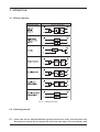
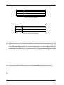
Version 1.0 August 2000 ® www.behringer.com ENGLISH VIRTUALIZER PRO DSP1024P User´s Manual VIRTUALIZER PRO DSP1024P SAFETY INSTRUCTIONS CAUTION: To reduce the risk of electrical shock, do not remove the cover (or back). No user serviceable parts inside; refer servicing to qualified personnel. WARNING: To reduce the risk of fire or electrical shock, do not expose this appliance to rain or moisture. This symbol, wherever it appears, alerts you to the presence of uninsulated dangerous voltage inside the enclosure - voltage that may be sufficient to constitute a risk of shock. This symbol, wherever it appears, alerts you to important operating and maintenance instructions in the accompanying literature. Read the manual. DETAILED SAFETY INSTRUCTIONS: All the safety and operation instructions should be read before the appliance is operated. Retain Instructions: The safety and operating instructions should be retained for future reference. Heed Warnings: All warnings on the appliance and in the operating instructions should be adhered to. Follow instructions: All operation and user instructions should be followed. Water and Moisture: The appliance should not be used near water (e.g. near a bathtub, washbowl, kitchen sink, laundry tub, in a wet basement, or near a swimming pool etc.). Ventilation: The appliance should be situated so that its location or position does not interfere with its proper ventilation. For example, the appliance should not be situated on a bed, sofa rug, or similar surface that may block the ventilation openings, or placed in a built-in installation, such as a bookcase or cabinet that may impede the flow of air through the ventilation openings. Heat: The appliance should be situated away from heat sources such as radiators, heat registers, stoves, or other appliance (including amplifiers) that produce heat. Power Source: The appliance should be connected to a power supply only of the type described in the operating instructions or as marked on the appliance. Grounding or Polarization: Precautions should be taken so that the grounding or polarization means of an appliance is not defeated. Power-Cord Protection: Power supply cords should be routed so that they are not likely to be walked on or pinched by items placed upon or against them, paying particular attention to cords and plugs, convenience receptacles and the point where they exit from the appliance. Cleaning: The appliance should be cleaned only as recommended by the manufacturer. Non-use Periods: The power cord of the appliance should be unplugged from the outlet when left unused for a long period of time. Object and Liquid Entry: Care should be taken so that objects do not fall and liquids are not spilled into the enclosure through openings. Damage Requiring Service: The appliance should be serviced by qualified service personnel when: - The power supply cord or the plug has been damaged; or - Objects have fallen, or liquid has been spilled into the appliance; or - The appliance has been exposed to rain; or - The appliance does not appear to operate normally or exhibits a marked change in performance; or - The appliance has been dropped, or the enclosure damaged. Servicing: The user should not attempt to service the appliance beyond that is described in the Operating Instructions. All other servicing should be referred to qualified service personnel. 2 VIRTUALIZER PRO DSP1024P FOREWORD Dear Customer, Welcome to the team of VIRTUALIZER PRO users and thank you very much for expressing your confidence in BEHRINGER products by purchasing this unit. It is one of my most pleasant tasks to write this letter to you, because it is the culmination of many months of hard work delivered by our engineering team to reach a very ambitious goal: making an outstanding device better still. The VIRTUALIZER PRO has for quite a long time been a standard tool used by numerous studios and P.A. rental companies. The task to improve one of our best-selling products certainly meant a great deal of responsibility, which we assumed by focusing on you, the discerning user and musician. It also meant a lot of work and night shifts to accomplish this goal. But it was fun, too. Developing a product usually brings a lot of people together, and what a great feeling it is when everybody who participated in such a project can be proud of what weve achieved. It is our philosophy to share our joy with you, because you are the most important member of the BEHRINGER family. With your highly competent suggestions for new products youve greatly contributed to shaping our company and making it successful. In return, we guarantee you uncompromising quality (manufactured under ISO9000 certified management system) as well as excellent technical and audio properties at an extremely favorable price. All of this will enable you to fully unfold your creativity without being hampered by budget constraints. We are often asked how we can make it to produce such high-grade devices at such unbelievably low prices. The answer is quite simple: its you, our customers! Many satisfied customers means large sales volumes enabling us to get better conditions of purchase for components, etc. Isnt it only fair to pass this benefit back to you? Because we know that your success is our success, too! I would like to thank all people whose help on Project VIRTUALIZER PRO has made it all possible. Everybody has made very personal contributions, starting from the designers of the unit via the many staff members in our company to you, the user of BEHRINGER products. My friends, its been worth the trouble! Thank you very much, Uli Behringer 3 VIRTUALIZER PRO DSP1024P VIRTUALIZER PRO Ultra-high performance Digital Multi-Effects Processor powered by a 24-bit high-speed Digital Signal Processor (DSP) DSP1024P 4 VIRTUALIZER PRO DSP1024P TABLE OF CONTENTS 1. INTRODUCTION .....................................................................................................................6 1.1 1.2 1.3 1.4 The design concept ......................................................................................................................... 6 Before you begin ............................................................................................................................. 7 Control elements ............................................................................................................................. 7 The effect algorithms ..................................................................................................................... 10 1.4.1 Reverb and delay algorithms ................................................................................................ 11 1.4.2 Special effects .................................................................................................................... 12 1.4.3 Modulation and pitch shifter effects ..................................................................................... 12 1.4.4 Effect algorithm combinations (multi-effects programs) ........................................................ 12 1.4.5 Dual-mode effects algorithms .............................................................................................. 13 2. OPERATION .......................................................................................................................... 14 2.1 2.2 2.3 2.4 2.5 Effects structure ............................................................................................................................ Selecting presets .......................................................................................................................... Editing programs ........................................................................................................................... Saving programs ........................................................................................................................... MIDI control ................................................................................................................................... 14 14 15 15 15 3. APPLICATIONS ..................................................................................................................... 17 3.1 3.2 3.3 3.4 3.5 3.6 Level setting .................................................................................................................................. Using the VIRTUALIZER PRO in the aux bus ................................................................................ Using the VIRTUALIZER PRO in the insert path ............................................................................ Using the VIRTUALIZER PRO as an effects device for instruments ............................................... Using the VIRTUALIZER PRO in a MIDI system ............................................................................ Saving data via MIDI ...................................................................................................................... 17 17 18 19 20 20 4. TECHNICAL BACKGROUND .............................................................................................. 21 4.1 Reverberation and reflection .......................................................................................................... 4.1.1 Reverberation chambers ...................................................................................................... 4.1.2 Spring and plate reverb ........................................................................................................ 4.1.3 Digital reverb ....................................................................................................................... 21 22 22 23 5. INSTALLATION ..................................................................................................................... 24 5.1 5.2 5.3 5.4 Mains connection .......................................................................................................................... Audio connections ........................................................................................................................ MIDI connections .......................................................................................................................... Operating Level switch .................................................................................................................. 24 24 25 26 6. APPENDIX ............................................................................................................................. 26 6.1 6.2 6.3 6.4 Parameter overview ....................................................................................................................... Delay values / increments for presets 10 and 11 ........................................................................... MIDI Implementation ..................................................................................................................... Default settings ............................................................................................................................. 26 27 28 29 7. SPECIFICATIONS ................................................................................................................. 30 8. WARRANTY ........................................................................................................................... 31 5 VIRTUALIZER PRO DSP1024P 1. INTRODUCTION With the BEHRINGER VIRTUALIZER PRO you have purchased a very powerful multi-effects processor which offers both first-class reverb sounds and various other effect algorithms. Although you will find a high number of effect types 32 newly developed effect types with more than 700 variations the VIRTUALIZER PRO can be operated easily and intuitively with its logically structured user interface. To generate reverberation that is very natural in character, we at BEHRINGER developed innovative virtual acoustics algorithms which allow for computing all room and reverb parameters with absolute pro-level quality and a highly natural sound character. Despite extensive computing work which is done in the DSP1024P by a dual-engine 24-bit processor, the VIRTUALIZER PRO can be operated easily and conveniently. All parameter edits are performed with the jog wheel (rotary control). 100 presets are available to store user-defined programs. However, the DSP1024P is by no means limited to excellent reverb and delay programs. In addition to the simulation of classic plate reverbs, the VIRTUALIZER PRO gives you extraordinary modulation effects (such as chorus and flanger), plus a few special-purpose variants, e.g. a musical pitch shifter as well as tremolo and rotary speaker simulations. With the vocoder and vocal distortion effect programs, you even have ultra-modern effects available that the DSP1024P generates with absolute realism. A very special feature are the high and low filters which can be freely edited and directly selected in each preset. With these filters you can fine-tune the sound of your presets to match any given room characteristics a time saving feature especially for live applications, where every second counts. Additionally, the DSP1024P offers delay times of up to 5.1 seconds in stereo mode. Not only will the VIRTUALIZER PRO convince you with its logical and easy-to-operate user interface, its technical features, too, are quite impressive. The following criteria ensure the pro-level processing of audio signals: s Extremely low-noise and high-precision 24-bit AD/DA converters. s A professional sampling rate of 46 kHz ensures a high signal resolution with a frequency response ranging from 20 Hz to 20 kHz. s The 24-bit processor features two sections (dual-engine software), each processing one independent audio channel. s Like all BEHRINGER products, the DSP1024P uses only high-grade components and circuitry. With its complete MIDI implementation the DSP1024P can be integrated in any MIDI system. Our free VIRTUALIZER design MIDI software editor (available at www.behringer.com) enables you to program the VIRTUALIZER PRO from your personal computer, and the MIDI interface allows for transmitting data from the DSP1024P and store them on an external storage medium. For example, you can use sys-ex dumps to send all presets and settings to your sequencer program and reload them from there whenever you want. + The following instructions manual will introduce you to the BEHRINGER VIRTUALIZER PRO and its various functions. After reading the manual carefully, make sure it is always on hand for future reference. 1.1 The design concept The philosophy behind BEHRINGER products guarantees a no-compromise circuit design and employs the best choice of components. Top-quality 24-bit AD/DA converters which belong to the best components available owing to its outstanding specifications and excellent sonic characteristics. Two 24-bit DSPs are used as the heart of the VIRTUALIZER PRO. These perform the precise calculations needed for the processing of the complex algorithms. Additionally, the VIRTUALIZER PRO uses high quality resistors and capacitors with very tight tolerances, high-grade switches, low-noise operational amplifiers as well other selected components. The VIRTUALIZER PRO DSP1024P uses SMD technology (Surface Mounted Device). These subminiature components known from aerospace technology allow for an extreme packing density, plus the units reliability could be improved. Additionally, the unit is manufactured in compliance with a ISO9000 certified management system. 6 1. INTRODUCTION VIRTUALIZER PRO DSP1024P 1.2 Before you begin Your BEHRINGER VIRTUALIZER PRO was carefully packed in the factory and the packaging was designed to protect the unit from rough handling. Nevertheless, we recommend that you carefully examine the packaging and its contents for any signs of physical damage, which may have occurred in transit. + If the unit is damaged, please do not return it to us, but notify your dealer and the shipping company immediately, otherwise claims for damage or replacement may not be granted. Shipping claims must be made by the consignee. The BEHRINGER VIRTUALIZER PRO fits into one standard 19" rack unit of space (1 3/4"). Please allow at least an additional 4" depth for the connectors on the back panel. Be sure that there is enough space around the unit for cooling and please do not place the VIRTUALIZER PRO on high temperature devices such as power amplifiers etc. to avoid overheating. + Before you connect your VIRTUALIZER PRO to the mains, please make sure that your local voltage matches the voltage required by the unit. The mains connection of the VIRTUALIZER PRO is made by using a mains cable and a standard IEC receptacle. It meets all of the international safety certification requirements. Please make sure that all units have a proper ground connection. + + Please make sure that all units have a proper ground connection. For your own safety, do not remove the ground connection within the units or at the supply, or fail to make this connection at all. Please ensure that only qualified persons install and operate the VIRTUALIZER PRO. During installation and operation the user must have sufficient electrical contact to earth. Electrostatic charges might affect the operation of the VIRTUALIZER PRO! See chapter 5 INSTALLATION for further details. As a standard the audio inputs and outputs on the BEHRINGER VIRTUALIZER PRO are fully balanced. If possible, connect the unit to other devices in a balanced configuration to allow for maximum interference immunity. The automatic servo function detects unbalanced connections and compensates the level difference automatically (6 dB correction). The MIDI links (IN/OUT/THRU) are made over standardized DIN patch cords. The data communication is isolated from ground by opto-couplers. 1.3 Control elements 7 VIRTUALIZER PRO DSP1024P 8 VIRTUALIZER PRO DSP1024P 8 Use the ENGINE R key to select the right audio channel (similar to : ENGINE L). If you wish to process the left and right audio channels simultaneously (couple mode), press both ENGINE keys together. In couple mode both ENGINE LEDs light up. Whenever you edit one of the two audio channels and then switch to couple mode, the parameters of the active channel will be copied to the other; i.e if you press ENGINE L before R, left will be copied to right. When parameters cannot be adjusted separately in a specific algorithm, the DSP1024P switches to couple mode automatically. 9 In each preset you can edit at least two parameters in addition to the preset variation. Use the EDIT A key to select the first parameter. The exact parameter assignment can be seen from the parameter list printed on top of the unit. 10 The EDIT B key allows you to modify the second parameter as required. 11 To give your programs the finishing touch, the VIRTUALIZER PRO incorporates two filters. Use the EQ HI key to raise or lower the high-frequency portions of the effect program. 12 The EQ LO key activates a filter which processes the low-frequency portions of your preset. 13 The IN/OUT key enables you to bypass the DSP1024P. The green LED lights up as soon as the VIRTUALIZER PRO is activated. Depending on the Mix mode adjusted (see below), this key can also be used to activate the Mute function. Additionally, the green LED starts flashing whenever MIDI data are being received. 14 Use the STORE key to save the edited program to a user preset as shown in the display. 100 user presets are available on the DSP1024P. Press the key once, select a memory location (number) with the JOG WHEEL, then press the key again to store the preset. 15 Use the POWER switch to switch the VIRTUALIZER PRO on or off. Key combinations To protect the DSP1024P against user errors, three important edit commands have been implemented as a series of key combinations. For example, in normal operating modes, the presets cannot be reset to their factory defaults, so as to secure your own programs as safely as possible. Please proceed as follows to reinitialize the preset default settings: s Keep the keys EFFECT and STORE pressed before powering up the VIRTUALIZER PRO. Then switch on the DSP1024P and keep the two keys pressed for about two seconds. The program numbers are counted up and reset to their original default settings. The VIRTUALIZER PRO provides two methods to mix the input and the effect signals (External Mix and Internal Mix modes). Select External Mix mode to use the DSP1024P with a mixing console: in this mode all presets are set to 100% effect intensity, i.e. you can use the aux return busses of your console to add the processed signal to the original signal. In External Mix mode the IN/OUT key is used to bypass the unit. Heres how to enter External Mix mode: s With the unit switched on, press the Mix mode key combination, i.e. the keys EQ LO and EQ HI. The VIRTUALIZER PRO enters Mix mode. When the display shows two dashes, the DSP1024P is in External Mix mode, and when a figure is displayed, Internal Mix mode is selected. To toggle between the two modes, simply press both EQ keys for about 2 seconds. In Internal Mix mode you can use the jog wheel to freely select the effect intensity in each preset within a range from 0% to 100%, a highly useful feature, for instance, to insert the DSP1024P in the effect loop of a guitar amp. Good results can be achieved with settings between 20% and 50%. Another key combination can be used to enter MIDI mode. With the VIRTUALIZER PRO switched on, proceed as follows: s Keep the keys IN/OUT and STORE pressed for about two seconds, the DSP1024P automatically enters MIDI mode. Use the IN/OUT key to step through the various MIDI parameters. Press any other key to quit MIDI mode. 1. INTRODUCTION 9 VIRTUALIZER PRO DSP1024P 10 VIRTUALIZER PRO DSP1024P 1.4.1 Reverb and delay algorithms Cathedral: Reverb program that generates long and dense reverberation, much like the natural reverb ambience found in churches or cathedrals. Particularly suitable for solo instruments and voices. VARIATION modifies the decay time, EDIT A adjusts the differences between tiled and angular walls (diffusion), while EDIT B ENGINE L governs the early reflections and EDIT B ENGINE R the brilliance of the reverb signal. Plate: The sound of early reverb plates. The decay time can be set from 0-9 s using VARIATION. EDIT A determines the pre-delay by changing the perceived size of the room, EDIT B uses ENGINE L to enhance the stereo image and ENGINE R to modify the room brilliance. A classic reverb program for drums and solo voices. Small Hall: Simulation of a small, highly reverberating hall. Use short reverb times (VARIATION) to process drum instruments or medium reverb times to enhance wind instruments. EDIT A controls diffusion, EDIT B early reflections (ENG. L) and stereo width (ENG. R). Room: You can clearly hear the walls of this room as they are reflecting the sound. Their characteristics can be changed with EDIT B from reflective (tiles, marble) to absorbent (carpets, curtains). Use VARIATION (reverb time / room size) to create any room type from small store rooms to large living rooms. EDIT A governs the pre-delay. A useful program for reverb that isnt directly noticable (rap, hip hop vocals) or to make dry recordings of instruments sound natural again. Very all-round effect. Studio: Middle to large rooms that can be modified in their wall characteristics (EDIT B ENG. R), early reflections (EDIT B ENG. L), position of sound source (= pre-delay: EDIT A) and size (VARIATION). Creates a natural and multipurpose sound. Concert: Use VARIATION (reverb time) to create a small theater or large concert hall, determine the distance to the stage (= predelay: EDIT A), the distance to neighboring walls (= early reflections: EDIT B ENG. L) and their structure (= diffusion: EDIT B ENG. R). Stage: Wonderful reverb, for example, to provide keyboard pads or acoustic guitars with width and depth (EDIT B ENG. R = stereo width), and to make them sound fresher (EDIT B ENG. L = brilliance). Additionally, you can set the reverb time with VARIATION and the diffusion with EDIT A. Designed for live applications and mixdown. 11 VIRTUALIZER PRO DSP1024P Reverse Reverb: A reverb program with an inverted amplitude envelope, i.e. the effect starts softly and then increases in volume. This effect used to be created by playing a tape in reverse direction, recording the reverb signal, and then playing back the tape in forward direction again, with the result that the reverb signal was played back before the actual input signal. VARIATION controls the length of the signal, EDIT A the delay, and EDIT B the threshold above which the effect responds. 12 VIRTUALIZER PRO DSP1024P Tremolo & Delay: Since trip hop has become trendy, this effect originally found in guitar amps is used to produce a more or less fast and intensive variation of volume (with an additional panorama effect included in the DSP1024P). The modulation speed is controlled with VARIATION, the intensity with EDIT A ENGINE L, and the panning rhythm with EDIT B ENGINE L. This algorithm belongs to the group of multi-effects programs and is combined with a delay. Delay time is set with EDIT A ENGINE R ranging from 0 to 630 ms (10 ms increments) feedback is set with EDIT B ENGINE R. 13 VIRTUALIZER PRO DSP1024P 2. OPERATION 2.1 Effects structure Fig. 2.1: Effects structure 2.2 Selecting presets The VIRTUALIZER PRO stores 100 user-definable presets. After power-up, the unit automatically recalls the preset last used. To select another preset, use the JOG WHEEL to enter the preset number of your choice. Turn the wheel clockwise to increment the preset number, or counterclockwise to decrement it. + 14 Please note that the VIRTUALIZER PRO generally activates the newly selected presets only after about one second, which is indicated by a dot in the lower right corner of the display. After 2. OPERATION VIRTUALIZER PRO DSP1024P + loading the data, the VIRTUALIZER PRO enables the preset and the dot disappears. This brief interruption avoids the direct activation of every preset, as you scroll through the preset list with the JOG WHEEL. Otherwise incomplete parameter remnants of presets could reach the audio outputs of the VIRTUALIZER PRO, with possibly disastrous consequences, especially when using a high-power P.A. system. Thus, the VIRTUALIZER PRO makes sure that no unwanted programs are loaded unintentionally. Additionally, you can rotate the JOG WHEEL at high speed and still have the time to specifically select the preset of your choice, instead of any of its neighbours. The effect algorithms may have greatly varying output levels, reduce the sensitivity (input gain) of subsequent devices before changing programs. 2.3 Editing programs Editing programs is easy on the VIRTUALIZER PRO. Basically, all essential parameters can be selected directly via the keypad and edited with the JOG WHEEL. The list to the left of the DISPLAY summarizes the effect algorithms that the VIRTUALIZER PRO can generate. Just press the EFFECT key to recall these basic algorithms and directly select them with the JOG WHEEL. With the VARIATION key you can modify the selected effect in full detail, because each variation does not only comprise one parameter but a set of several parameters. Thus, you can use the various variations to tailor the sound of an effects program to suit your specific needs. The EDIT A and B keys enable you to edit essential single parameters of the selected effects program, while the EQ LO and EQ HI keys allow for adapting your own presets to match specific room acoustics or sound preferences. Use the ENGINE L and ENGINE R keys to edit the left or right audio channel settings. Of course, you can edit both channels at the same time in couple mode. When entering couple mode, the VIRTUALIZER PRO copies the parameter settings of the channel last activated to the other channel, so that both of them have an identical set of parameter values. Finally, you can also save the changes made to the preset. 2.4 Saving programs Use the STORE key to save an edited preset. Basically, all parameter changes can be saved. Whenever youre editing a preset, the DISPLAY starts flashing to indicate that the edits will be saved only when you confirm them by pressing the STORE key twice. Example: s You recall a program for editing. Then you edit the preset as desired using the function keys and the jog wheel. During this process, the flashing STORE key reminds you that the preset settings have been changed but not saved yet. Press the STORE key once. The display reads the current preset number and starts flashing. To keep the original preset, use the jog wheel to select another preset that can be overwritten. Press the STORE key again to save the changes to the selected preset. If you wish to overwrite the original preset, simply press the STORE key twice (after editing) to save all changes you have made. + Whenever you have edited a preset and pressed the STORE key twice, all previous settings in this preset are erased and overwritten with the new parameter values. However, if you wish to keep the original preset, use the JOG WHEEL to select another preset before you press the STORE key a second time. 2.5 MIDI control Use the MIDI key combination to select the MIDI parameters you wish to adjust. For this purpose, keep the IN/OUT and the STORE keys pressed for about two seconds. All parameters can be edited with the JOG WHEEL and these two keys. The MIDI menu includes six pages which you can select by pressing the IN/OUT key (upwards) and the STORE key (downward). On the first page you can select the MIDI channel. The DISPLAY shows a small c (= channel). The JOG WHEEL adjusts a channel from 1 through 16. To switch off the MIDI function, simply select the 0 value (displayed as -). On the second page you can select MIDI Omni mode, i.e. the unit transmits/receives on all 16 MIDI channels. The DISPLAY reads O (= Omni). Use the JOG WHEEL to activate (1) or deactivate (0) Omni mode. 2. OPERATION 15 VIRTUALIZER PRO DSP1024P The third page allows for configuring controller commands. On its right-hand side, the DISPLAY shows a capital C (= Controller). The JOG WHEEL selects one of the following four controller modes: Display 0 1 2 3 Mode No controller data are transmitted. Controller data are received but not transmitted. Controller data are transmitted but not received. Controller data are transmitted and received. Tab. 2.1: Controller settings For further details see table 6.4 in section 6 APPENDIX. The fourth page gives you access to the program change setup. The DISPLAY shows a capital P (= Program). Here, too, four modes can be selected with the JOG WHEEL, as follows: Display 0 1 2 3 Modus Program Changes are not transmitted. Program Changes are received but not transmitted. Program Changes are transmitted but not received. Program Changes are transmitted and received. Tab. 2.2: Program change settings The fifth page of the MIDI menu shows the store enable flag represented by a capital S in the DISPLAY. The value 0 disables the reception of controller #28, and therefore protects the user presets from being modified via MIDI. Accordingly, the value 1 enables MIDI controller #28 so that you can modify or replace presets with a remote MIDI device or a sequencer. In this case the actual settings will be stored directly to the location that corresponds to the controller value. + Attention! Since the store enable mode allows you to access memory locations directly via MIDI, it is possible that stored presets will be replaced or altered if controller #28 messages are sent on the same MIDI channel. The purpose of this mode is to facilitate MIDI backup and restore operations without express confirmation at the VIRTUALIZER PRO. It is therefore recommended to disable (flag = 0) this mode as soon as the intended data transfer has ended. This is done automatically when you switch off the VIRTUALIZER PRO. On the sixth and last page, you can access the System Exclusive functions. This is indicated by a d (for dump) in the DISPLAY. To the left of this d a number is displayed: - 0 means that no SYSEX data will be sent or accepted. - 1 will enable the VIRTUALIZER PRO to receive data. When STORE is pressed the unit will wait for data, this is shown by flashing dots (LEDs) in the DISPLAY. The MIDI key LED flashes signaling that SYSEX data is being received. - 2 will enable the VIRTUALIZER PRO to send a bulk dump. Start your MIDI sequenzer program and press STORE on the DSP1024P to start the transmission. To load these settings again, select 1, press STORE and start your MIDI sequenzer program. + During a bulk dump, all audio functions of the VIRTUALIZER PRO will be deactivated. If you press the IN/OUT key again on the sixth page, the VIRTUALIZER PRO quits MIDI setup mode. At all times you can press any other key to leave the MIDI setup directly. The full-featured MIDI implementation of the VIRTUALIZER PRO allows for easily integrating of the VIRTUALIZER PRO into any MIDI system. s MIDI IN Any MIDI data sent to the VIRTUALIZER PRO (sequenzer, MIDI footswitch, etc.) is received via the MIDI IN jack. For example, when you wish to use the VIRTUALIZER PRO as an effects devices for your guitar rack, you can connect the MIDI IN jack to a MIDI footswitch that allows for selecting program presets. If your rack includes another MIDI effects devices (e.g. a multi-effects processor), the data sent from the MIDI footswitch 16 2. OPERATION VIRTUALIZER PRO DSP1024P can be routed via the VIRTUALIZER PROs MIDI THRU jack to your multi-effects processor. s MIDI THRU The MIDI THRU jack is used to loop through incoming MIDI data, i.e. any control data received at the MIDI IN of the VIRTUALIZER PRO can be transmitted via the MIDI THRU jack to other MIDI devices/instruments. s MIDI OUT The MIDI OUT jack allows for transmitting MIDI data that originate from the VIRTUALIZER PRO. The VIRTUALIZER design editor software (free download at www.behringer.com) enables you to control the VIRTUALIZER PRO from your personal computer. 3. APPLICATIONS The BEHRINGER VIRTUALIZER PRO is a highly flexible device that can be used for a wide variety of applications. Prior to a presentation of the VIRTUALIZER PROs many uses, please note the following remarks on how to set signal levels correctly. 3.1 Level setting Take care to set all levels properly on the VIRTUALIZER PRO! Low levels deteriorate the dynamics of the music signal, which results in a poor, weak and noisy sound. On the other hand, excess levels overdriving the converters in the VIRTUALIZER PRO should also be avoided. Digital distortion is (unlike its analog counterpart) very unpleasant to hear as it does not occur gradually but abruptly. Use the input level meter of the VIRTUALIZER PRO to adjust the input signal, so that the Clip LED flickers only rarely. Make sure that it never lights up permanently! 3.2 Using the VIRTUALIZER PRO in the aux bus By using the VIRTUALIZER PRO in an aux bus of your mixing console you can feed the channel signals of one, several or even all console channels into the VIRTUALIZER PRO, i.e. for each channel you can use the aux busses to separately determine the reverb levels of, for instance, various drum sounds: while lots of reverb is applied to the snare drum, the effect intensity could be reduced in the channels assigned to the tom-toms. To use the VIRTUALIZER PRO in the aux bus, the unit must be wired as follows: 17 VIRTUALIZER PRO DSP1024P Connect the two Input phone jacks with the Aux Send outputs of the mixing console, and the Output jacks of the VIRTUALIZER PRO with the Aux Return inputs of the console. If you want to use the BEHRINGER VIRTUALIZER PRO in mono or dual mode, connect one audio channel (left or right) to one aux bus. + Turn down the volume on your amplifier to protect your equipment against damage. All devices you wish to interconnect should remain switched off until they are wired correctly. Lets suppose you wish to use the VIRTUALIZER PRO in a live application, interfaced with the F.O.H. mixer, to enhance the guitar sound with a subtle chorus effect. Connect the VIRTUALIZER PRO to the aux bus of your mixing console (fig. 3.1). Connect the units to the mains and adjust the operating level(s) if necessary. Switch on the VIRTUALIZER PRO and set the levels appropriately (see 3.1). Press the Mix combination to make sure that the unit is set to Mix External mode. Press the EFFECT key and use the JOG WHEEL to select and thus activate the chorus effect (#19). Slowly turn up the aux bus level until the effect portion added to the guitar signal suits your needs. Subsequently, you can make all necessary fine-adjustments. We assume that you wish to edit the modulation frequency of the chorus effect: press the VARIATION key and set the modulation frequency with the JOG WHEEL. To set the modulation delay, press the EDIT A key. The modulation depth of the chorus effect can be set by pressing the EDIT B key. Having edited all parameters as desired, you can save the changes to the original (or any other) preset. 3.3 Using the VIRTUALIZER PRO in the insert path Basically, you can also insert the VIRTUALIZER PRO in a channel or subgroup of your mixing console. Use a dedicated insert cable. Inserting the VIRTUALIZER PRO in a single channel will be useful only if you wish to process a specific signal (e.g. vocals) with the VIRTUALIZER PRO, or if any other insert facilities of your mixing console are already in use. 18 VIRTUALIZER PRO DSP1024P 3.4 Using the VIRTUALIZER PRO as an effects device for instruments With its extensive MIDI implementation the VIRTUALIZER PRO can also be used, for instance, as a multieffects device in a guitar rack. Of course, you can connect it up in both stereo and mono. The following hints illustrate the VIRTUALIZER PROs versatility if used with a guitar amp. 19 VIRTUALIZER PRO DSP1024P The VIRTUALIZER PRO may also be inserted between the outputs of a keyboard and the inputs of a mixing console. If required, adjust the levels with the OPERATING LEVEL switch. 3.5 Using the VIRTUALIZER PRO in a MIDI system With its built-in MIDI interface the VIRTUALIZER PRO can be integrated into any MIDI system. It transmits and receives both program change and controller change information to perform program changes via MIDI from a sequenzer or any other MIDI device. Wire and set up the VIRTUALIZER PRO as shown below: 20 VIRTUALIZER PRO DSP1024P 4. TECHNICAL BACKGROUND 4.1 Reverberation and reflection Prior to simulating the physical phenomena of reverberation and reflection, it is necessary to analyze how reverb is generated, and how it is perceived by human hearing. In a concert hall the sound the listener hears comprises both the source signals (e.g. acoustical instruments, P.A. system) and thousands of reflections of these primary signals, which bounce off floor, ceiling and walls to reach the ear after a short delay. These reflections represent thousands of echoes of the direct signal, which are not perceived any longer as single echoes, but due to their sheer number as reverberation. Basically, the reflected signal portions reach the ear later than the source signal, and the very fact that they do not arrive from the same direction as the direct signal (see fig. 4.1), makes it possible to hear spatial information, i.e. to perceive the direct signal as if it is embedded in the room acoustics. Direct Sound Stage Ea rly Re cti on rly s e efl s on cti fle R Ea Listening Position Diffuse Reflections Fig. 4.1: Direct and reflected sounds reaching the listeners ear Spatial information is an important means of orientation, because human hearing is also used to determine the position of a sound source. In certain situations, this capability can be very useful or even of vital importance. The fact that we can actually hear the size of a room shows how strongly developed the human sense of hearing actually is. Based on the reflectivity of a room, we can also distinguish (though we often dont know how) the materials it consists of. In large rooms with high tiled walls reverberation is generally very dense and needs some time to decay, while a small room with many objects in it (furniture, carpets, etc.) features very short reverberation often not even perceived as such. Nevertheless, this extremely short reverb does exist, which is the reason why many designers of reverb devices (such as our VIRTUALIZER PRO) implement several basic reverb types and give them specific room names. It is quite natural, for example, that a reverb preset called Cathedral produces a long and highly dense reverb, while a Room program usually represents the acoustics of a room that is much smaller in size. In addition to the capability of human hearing to determine the direction from where a sound phenomenon arrives, we can also hear modulations of acoustic events. Of importance in this context is the frequency of the modulated signals. Frequency modulations below 100 Hz are virtually inaudible. However frequency 4. TECHNICAL BACKGROUND 21 VIRTUALIZER PRO DSP1024P modulations can clearly be heard when occurring in the midrange frequency band, due to the sensitivity of human hearing. The ear immediately detects changes in midrange frequencies, while its sensitivity to frequency modulation in the extreme low end of the frequency spectrum is reduced. Frequency modulation can also be used to produce wanted effects. The popular chorus effect, for instance, is basically the sum of a variety of frequency modulations. The original signal is slightly delayed in the chorus algorithm, then added again and modulated by means of an oscillator. Subsequently, modulating frequencies (of different pitch) are applied to the original signal, which produces the well-known floating chorus sound. Basically, frequency modulation is the starting point for all kinds of chorus-type effects: by simply adding the delayed signal, without modulating the original, you can produce a delay effect. Since chorus effects use very short delay times, the resulting delay effect is not perceived as such. However, when you increase the delay time, there is a clear gap between original and effect signals, and delay becomes audible. A highly intensive effect can be achieved by combining reverb/delay programs with modulation effects. For this reason, the BEHRINGER VIRTUALIZER PRO also features multi-effects programs combining reverb or delay with, for example, a chorus effect. In addition to the multi-effects programs and special-purpose effects, most of the VIRTUALIZER PROs effect programs offer pure reverb programs, because common reverb is still the most important effect for mix-down or live applications. Therefore, we at BEHRINGER want to provide you with a variety of reverb programs, so that you have appropriate presets available for each specific application. 22 VIRTUALIZER PRO DSP1024P Room Plate Speaker Sender Microphone Receiver Fig. 4.2: Room reflections and reverb plate reflections Spring reverb devices use a similar principle, but their reverb sound is of inferior quality compared to a properly adjusted reverb plate. In particular, dynamic signals such as drums have a highly compressed and flat sound when they are reproduced with a spring reverb. Still, spring reverbs can be found even today in guitar amplifiers. Due to the speakers used in such amps, there are no extremely high frequencies to be processed, so lower reverb quality (in particular, in view of the cost) can be an acceptable alternative for guitarists. Yet, spring reverb designs suffer from a few drawbacks limiting their professional use: s The parameters of spring reverb devices cannot be modified or edited. To allow for different reverb decay times, you would need to alter the physical properties of the springs. s The clattering sound of spring reverbs is a much-dreaded effect, in particular, on stage. Shock can set the reverb spring in motion so that it hits against its enclosure. The resulting noise resembles that of thunder. s Spring reverb is of poor quality, especially with percussive signals, which is the reason why the use of such devices in recording studios is highly limited. 4.1.3 Digital reverb With the development of digital reverb devices, spring reverbs and reverb plates have almost completely vanished from the studio, because digital devices feature a wealth of advantages: s Excellent reverb quality. s Mass production allows for reducing the prices of digital reverb devices. s Many parameters can be modified and stored. s With their compact design digital devices are easily portable. s Digital devices need almost no maintenance and are virtually insusceptible to interference. Basically, digital reverberation tries to provide a virtual simulation of real (in specific situations even surreal) reverb phenomena by means of algorithms computed by an effects processor. The quality of this simulation largely depends on the software (algorithms), the performance features of the processor used and the quality of the AD/DA converters. Since natural reverb comprises thousands of single echoes, a fast processor must be used to perform the complex calculations needed. To make the reverb programs sound natural, appropriate software must be used to be able to control the most essential parameters of a reverb phenomenon. For example, signal diffraction, reflections from different kinds of material, phase shift and room resonances must be calculated. Consequently, digital devices allow editing of many more parameters than reverb plates or spring reverbs do. In almost all digital devices, (at least) the following parameters can be modified: s Pre-delay time: this parameter determines the time between the occurrence of original signal and first reflections. s Decay time: determines the duration of the reverb (in seconds). s High-damp: a function that allows for equalizing the reverberated sound in the higher frequency range. To simulate the sound of a heavily damped room, for instance, the high-frequency portions in the reverb signal must be reduced. 4. TECHNICAL BACKGROUND 23 VIRTUALIZER PRO DSP1024P 5. INSTALLATION 5.1 Mains connection The mains connection of the VIRTUALIZER PRO is made by using a mains cable and a standard IEC receptacle. It meets all of the international safety certification requirements. + Please make sure that all units have a proper ground connection. For your own safety, do not remove the ground connection within the units or at the supply, or fail to make this connection at all. Before you switch on the unit, check that it is configured to match your AC mains voltage requirements. If it does not comply, then it is necessary to switch the operating voltage to the correct supply requirements BEFORE turning on the unit, otherwise the unit could be severely damaged. You will find this combined fuse holder/voltage selector at the back, adjacent to the IEC receptacle. IMPORTANT: This does not apply for general export models which are built for one operating voltage only. The AC voltage selection is defined by the position of the fuse holder. If you intend to change the operating voltage, remove the fuse holder and twist it by 180 degrees before you reinsert it. Matching the two markers monitors the selected voltage. + If the unit is switched to an other operating voltage, the ruse rating must be changed. See the technical specifications in the appendix A safety fuse protects the unit from serious defects. If the fuse blows, this is a warning sign and always indicates that the circuit is overloaded. The fault must always be repaired before the fuse is replaced. If the safety fuse is faulty and needs replacing after the unit is repaired, please make sure that you replace it only with the identical type and rating. NEVER use fuses of different ratings or cover faulty fuses with aluminium foil. This can cause fire and electric shocks and will endanger your life and the lives of others. 5.2 Audio connections As standard, the BEHRINGER VIRTUALIZER PRO is installed with electronically servo-balanced inputs and outputs. The new circuit design features automatic hum and noise reduction for balanced signals and thus allows for trouble-free operation, even at high operating levels. Externally induced mains hum etc. will be effectively suppressed. The automatic servo-function recognizes the presence of unbalanced connectors and adjusts the nominal level internally to avoid level differences between the input and output signals (correction 6 dB). + 24 Please ensure that only qualified persons install and operate the VIRTUALIZER PRO. During installation and operation the user must have sufficient electrical contact to earth. Electrostatic charges might affect the operation of the VIRTUALIZER PRO! 5. INSTALLATION VIRTUALIZER PRO DSP1024P 25 26 1 2 3 4 5 6 7 8 9 10 11 12 13 14 15 16 17 18 19 20 21 22 23 24 25 26 27 28 29 30 31 32 VARIATION CATHEDRAL Reverb Time PLATE Reverb Time SMALL HALL Reverb Time ROOM Reverb Time STUDIO Reverb Time CONCERT Reverb Time STAGE Reverb Time VOCAL Reverb Time PERCUSSION Reverb Time DELAY Del. Coarse ECHO Del. Coarse GATED REVERB Gate Time REVERSE REVERB Gate Time VOCAL DISTORTION Distortion Type ROTARY SPEAKER Rotary Type VOCODER Vocoder Type PITCH FLANGER Mod. Frequency CHORUS Mod. Frequency TREMOLO & DELAY Mod. Frequency DELAY & REVERB Del. Mix PITCH & REVERB FLANGER & REVERB Mod. Frequency CHORUS & REVERB Mod. Frequency PITCH / REVERB FLANGER / REVERB Mod. Frequency CHORUS / REVERB Mod. Frequency TREMOLO / REVERB Mod. Frequency DELAY / REVERB PITCH / ECHO FLANGER / ECHO Mod. Frequency CHORUS / ECHO Mod. Frequency Nr. EFFECT EDIT A EDIT B ENGINE R ENGINE L ENGINE R Diffusion Early Reflections High Multiply Pre Delay Stereo Width High Multiply Diffusion Early Reflections Stereo Width Pre Delay Wall Damp Pre Delay Early Reflections Wall Damp Pre Delay Early Reflections Diffusion Liveliness Stereo Width Diffusion Pre Delay Early Reflections High Mulitiply High Frequency Decay Diffusion Delay Time Delay Time Feedback Feedback Delay Time Delay Time Feedback Feedback Gate Threshold Density Gate Threshold Pre Delay Delay Mix Delay Time (x 10 ms) Horn Speed Rotor Speed Vocoder Sens Vocoder Distortion Cent Semi Tone Semi Tone Cent Mod. Depth Mod. Depth Mod. Feedback Mod. Feedback Mod. Depth Mod. Delay Mod. Delay Mod. Depth Mod. Depth Del. Time (x 10 ms) Panning Delay Feedback Reverb Mix Del. Time (x 10 ms) Reverb Time Feedback Cent Reverb Time Semi Tone Reverb Mix Mod. Depth Reverb Time Mod. Feedback Reverb Mix Reverb Mix Mod. Delay Reverb Time Mod. Depth High Multiply Cent Reverb Time Semi Tone Mod. Depth Reverb Time Mod. Feedback High Multiply High Multiply Mod. Delay Reverb Time Mod. Depth Del. Time (x 10 ms) Reverb Time Delay Feedback High Multiply Del. Time (x 10 ms) Reverb Time Delay Feedback High Multiply Delay Feedback Cent Del. Time (x 10 ms) Semi Tone Mod. Depth Del. Time (x 10 ms) Mod. Feedback Delay Feedback Delay Feedback Mod. Delay Del. Time (x 10 ms) Mod. Depth ENGINE L VIRTUALIZER PRO DSP1024P 5.4 Operating Level switch To adapt the VIRTUALIZER PRO to the used operating level, the unit can be switched between homerecording level (-10 dBV) and professional level (+4 dBu). Use the LED bars on the frontpanel to determine the optimal setting. The Level indicators should read somewhere around -6 / -10 dB, while the clip LED should not light up at all. 6. APPENDIX 6.1 Parameter overview Tab. 6.1: Parameter overview of the different effect types 6. APPENDIX VIRTUALIZER PRO DSP1024P 6.2 Delay values / increments for presets 10 and 11 Variation Type 1 2 3 4 5 6 7 8 9 10 11 12 13 14 15 16 17 18 19 20 21 22 23 24 25 26 27 28 29 30 31 32 Edit A Delay (R) Delay (L) From (ms) Until (ms) From (ms) Until (ms) 0 315 0 315 320 635 320 635 640 955 640 955 960 1275 960 1275 0 315 320 635 0 315 640 955 0 315 960 1275 320 635 640 955 320 635 960 1275 640 955 960 1275 0 630 1280 1910 0 630 1920 2550 0 630 2560 3190 0 630 3200 3830 640 1270 1280 1910 640 1270 1920 2550 640 1270 2560 3190 640 1270 3200 3830 1280 1910 1920 2550 1280 1910 2560 3190 1280 1910 3200 3830 1280 1910 3840 4470 1920 2550 2560 3190 1920 2550 3200 3830 1920 2550 3840 4470 1920 2550 4480 5110 2560 3190 3200 3830 2560 3190 3840 4470 2560 3190 4480 5110 3200 3830 3840 4470 3200 3830 4480 5110 3840 4470 4480 5110 Step Size (L & R) 5 5 5 5 5 5 5 5 5 5 10 10 10 10 10 10 10 10 10 10 10 10 10 10 10 10 10 10 10 10 10 10 Fig. 6.2: Increment table for presets 10 and 11 6. APPENDIX 27 VIRTUALIZER PRO DSP1024P 6.3 MIDI Implementation MIDI Implementation Chart Function Basic Channel Mode Note Number Velocity After Touch Transmitted Recognized Remarks Default Changed Default Messages Altered OFF, 1 - 16 OFF, 1 - 16 1,2,3,4 X X X X X X X X X O 20 - 30 O (0-99) 1-100 X X X X X X X X X X True Voice Note ON Note OFF Key´s Ch´s Pitch Bender Control Progr. True # Change System Exclusive Song Pos System Song Sel Common Tune Clock System Commands Real Time Local ON/OFF All notes OFF Aux Active Sense Messages Reset Notes O = YES, X = NO Mode 1: OMNI ON, POLY Mode 2: OMNI ON, MONO Mode 3: OMNI OFF, POLY Mode 4: OMNI OFF, MONO OFF, 1 - 16 OFF, 1 - 16 1,2,3,4 X X X X X X X X X O 20 - 30 O (0-99) 1-100 X X X X X X X X X X memorized see add. Table Tab. 6.3: MIDI Implementation Chart Parameter Name Display Range Midi Control Number Effect 1..32 Variation 1..32 Engine Edit A 0..63 / -50..50 Edit B 0..63 / -12..12 EQ LO -16..16 EQ HI -16..16 Mix 0..100 Store 1..100 IN/OUT Mix Intern/Extern 0..100 / -(1) when effect has Cent function (2) when effect has Semi Tone function 20 21 22 23 24 25 26 27 28 29 30 Control Value Range LEDs Couple Left Right IN on IN off 0..31 0..31 0,1,2 0..63 / 0..100 (1) 0..63 / 0..24 (2) 0..33 0..33 0..100 0..99 0,1 0,1 Tab. 6.4: Controller functions with MIDI 28 6. APPENDIX 0 1 2 1 0 VIRTUALIZER PRO DSP1024P 6.4 Default settings No. Effect Variation 1 2 3 4 5 6 7 8 9 10 11 12 13 14 15 16 17 18 19 20 21 22 23 24 25 26 27 28 29 30 31 32 Cathedral Plate Small Hall Room Studio Concert Stage Vocal Percussion Delay Echo Gated Reverb Reverse Reverb Vocal Distortion Rotary Speaker Vocoder Pitch Flanger Chorus Tremolo & Delay Delay & Reverb Pitch & Reverb Flanger & Reverb Chorus & Reverb Pitch / Reverb Flanger / Reverb Chorus / Reverb Tremolo / Reverb Delay / Reverb Pitch / Echo Flanger / Echo Chorus / Echo 11 14 4 30 9 23 20 14 8 1 1 5 8 12 14 4 1 1 19 21 4 6 4 1 17 1 1 Engine Left Edit A Edit B 63 53 9 50 50 39 0 29 9 49 20 51 55 60 28 46 63 27 24 30 37 30 50 21 63 21 15 16 18 14 10 56 +0 +0 6 56 32 63 63 63 63 9 +6 +0 63 63 20 30 +0 +0 63 63 27 60 0 0 55 20 +0 +0 8 60 34 40 Engine Right Edit A Edit B 50 20 63 31 63 63 52 24 30 37 30 +0 +0 6 56 32 63 0 0 57 56 50 52 32 38 63 43 21 40 21 40 21 40 21 40 21 40 40 23 63 16 31 23 Tab. 6.5: Default settings 6. APPENDIX 29 VIRTUALIZER PRO DSP1024P 7. SPECIFICATIONS Analog Inputs Connectors Type Impedance Nominal Operating Level Max. Input Level XLR and 1/4" jack RF filtered, servo balanced input 60 kW balanced, 30 kW unbalanced -10 dBV to +4 dBu +16 dBu at +4 dBu nominal level, +2 dBV at -10 dBV nominal level Analog Outputs Connectors Type Impedance Max. Output Level XLR and 1/4" jack Electronically servo-balanced output stage 60 W balanced, 30 W unbalanced +16 dBu at +4 dBu nominal level, +2 dBV at -10 dBV nominal level System specifications Bandwidth Noise THD Crosstalk 20 Hz to 20 kHz, +/- 3 dB > 94 dB, unweighted, 20 Hz to 20 kHz 0.0075 % typ. @ +4 dBu, 1 kHz, Gain 1 < -76 dB MIDI Interface Type 5-Pin-DIN-Socket IN / OUT / THRU Digital Processing Converters Sampling Rate 24-bit Sigma-Delta, 64/128-times Oversampling 46,875 kHz Display Type 2 ½-digit numeric LED-Display Power Supply Mains Voltages Power Consumption Mains Connection USA/Canada 120 V ~, 60 Hz U.K./Australia 240 V ~, 50 Hz Europe 230 V ~, 50 Hz General Export Model 100 - 120 V ~, 200 - 240 V ~, 50 - 60 Hz 100 - 120 V ~: T 200 mA H 200 - 240 V ~: T 100 mA H 15 Watts max. Standard IEC receptacle Physical Dimensions (H * W * D) Net Weight Shipping Weight 1 3/4" (44.5 mm) * 19" (482.6 mm) * 7 1/2" (190.5 mm) app. 2 kg app. 3 kg Fuse BEHRINGER is constantly striving to maintain the highest professional standards. As a result of these efforts, modifications may be made from time to time to existing products without prior notice. Specifications and appearance may differ from those listed or illustrated. 30 7. SPECIFICATIONS VIRTUALIZER PRO DSP1024P 8. WARRANTY § 1 WARRANTY CARD/ONLINE REGISTRATION To be protected by the extended warranty, the buyer must complete and return the enclosed warranty card within 14 days of the date of purchase to BEHRINGER Spezielle Studiotechnik GmbH, in accordance with the conditions stipulated in § 3. Failure to return the card in due time (date as per postmark) will void any extended warranty claims. Based on the conditions herein, the buyer may also choose to use the online registration option via the Internet (www.behringer.com or www.behringer.de). § 2 WARRANTY 1. BEHRINGER (BEHRINGER Spezielle Studiotechnik GmbH including all BEHRINGER subsidiaries listed on the enclosed page, except BEHRINGER Japan) warrants the mechanical and electronic components of this product to be free of defects in material and workmanship for a period of one (1) year from the original date of purchase, in accordance with the warranty regulations described below. If the product shows any defects within the specified warranty period that are not due to normal wear and tear and/or improper handling by the user, BEHRINGER shall, at its sole discretion, either repair or replace the product. 2. If the warranty claim proves to be justified, the product will be returned to the user freight prepaid. 3. Warranty claims other than those indicated above are expressly excluded. § 3 RETURN AUTHORIZATION NUMBER 1. To obtain warranty service, the buyer (or his authorized dealer) must call BEHRINGER (see enclosed list) during normal business hours BEFORE returning the product. All inquiries must be accompanied by a description of the problem. BEHRINGER will then issue a return authorization number. 2. Subsequently, the product must be returned in its original shipping carton, together with the return authorization number to the address indicated by BEHRINGER. 3. Shipments without freight prepaid will not be accepted. § 4 WARRANTY REGULATIONS 1. Warranty services will be furnished only if the product is accompanied by a copy of the original retail dealers invoice. Any product deemed eligible for repair or replacement by BEHRINGER under the terms of this warranty will be repaired or replaced within 30 days of receipt of the product at BEHRINGER. 2. If the product needs to be modified or adapted in order to comply with applicable technical or safety standards on a national or local level, in any country which is not the country for which the product was originally developed and manufactured, this modification/adaptation shall not be considered a defect in materials or workmanship. The warranty does not cover any such modification/adaptation, irrespective of whether it was carried out properly or not. Under the terms of this warranty, BEHRINGER shall not be held responsible for any cost resulting from such a modification/adaptation. 3. Free inspections and maintenance/repair work are expressly excluded from this warranty, in particular, if caused by improper handling of the product by the user. This also applies to defects caused by normal wear and tear, in particular, of faders, potentiometers, keys/buttons and similar parts. 4. Damages/defects caused by the following conditions are not covered by this warranty: s misuse, neglect or failure to operate the unit in compliance with the instructions given in BEHRINGER user or service manuals. s connection or operation of the unit in any way that does not comply with the technical or safety regulations applicable in the country where the product is used. s damages/defects caused by force majeure or any other condition that is beyond the control of BEHRINGER. 5. Any repair or opening of the unit carried out by unauthorized personnel (user included) will void the warranty. 6. If an inspection of the product by BEHRINGER shows that the defect in question is not covered by the warranty, the inspection costs are payable by the customer. 7. Products which do not meet the terms of this warranty will be repaired exclusively at the buyers expense. BEHRINGER will inform the buyer of any such circumstance. If the buyer fails to submit a written repair order within 6 weeks after notification, BEHRINGER will return the unit C.O.D. with a separate invoice for freight and packing. Such costs will also be invoiced separately when the buyer has sent in a written repair order. § 5 WARRANTY TRANSFERABILITY This warranty is extended exclusively to the original buyer (customer of retail dealer) and is not transferable to anyone who may subsequently purchase this product. No other person (retail dealer, etc.) shall be entitled to give any warranty promise on behalf of BEHRINGER. § 6 CLAIM FOR DAMAGES Failure of BEHRINGER to provide proper warranty service shall not entitle the buyer to claim (consequential) damages. In no event shall the liability of BEHRINGER exceed the invoiced value of the product. § 7 OTHER WARRANTY RIGHTS AND NATIONAL LAW 1. This warranty does not exclude or limit the buyers statutory rights provided by national law, in particular, any such rights against the seller that arise from a legally effective purchase contract. 2. The warranty regulations mentioned herein are applicable unless they constitute an infringement of national warranty law. The information contained in this manual is subject to change without notice. No part of this manual may be reproduced or transmitted in any form or by any means, electronic or mechanical, including photocopying and recording of any kind, for any purpose, without the express written permission of BEHRINGER Spezielle Studiotechnik GmbH. BEHRINGER and VIRTUALIZER are registered trademarks. ALL RIGHTS RESERVED. © 2000 BEHRINGER Spezielle Studiotechnik GmbH. BEHRINGER Spezielle Studiotechnik GmbH, Hanns-Martin-Schleyer-Str. 36-38, 47877 Willich-Münchheide II, Germany Tel. +49 (0) 21 54 / 92 06-0, Fax +49 (0) 21 54 / 92 06-30 8. WARRANTY 31