1
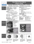
FALCON & FALCON XL
USER'S GUIDE
MOTION SENSORS FOR INDUSTRIAL DOORS
• FALCON: for high mounting
TECHNICAL
SPECIFICATIONS
Technology: Microwave and microprocessor
Transmitter frequency:
24.125 GHz
Transmitter radiated power: <20 dBm EIRP
Transmitter power density: < 5 mW/cm²
Mounting height
FALCON: from 11.5 to 23’
FALCON XL: from 6.5 to 11.5’
Tilt angle:
0° to 180° in elevation
Detection zone (typical)
Wide pattern (FALCON XL): 13’ (W) x 6.5’ (D)
for a mounting height of 8.2’
Narrow pattern (FALCON): 13’ (W) x 16’ (D)
for a mounting height of 16’
Detection mode:
movement
Minimum detection speed:
2.2 in/s (measured in the
sensor axis)
Supply voltage:
12V to 24V AC +/- 10%
12V to 24V DC +30% / -10%
Mains frequency:
50 to 60 Hz
Power consumption: < 2W
Output relay: free of potential changeover contact
Max contact voltage : 42V AC/ DC
Max contact current: 1A (resistive)
Max switching power: 30W (DC) / 60 VA (AC)
• FALCON XL: for low mounting
Hold time: 0.5s to 9s (adjustable)
Manual adjustment:
• orientation of sensing field (mechanically)
• multiple functions (by push buttons).
Remote control adjustments:
• Sensitivity.
• Hold time.
• Detection mode.
• Pedestrian and parallel traffic rejection mode.
• Relay configuration.
Temperature range : -22°F to 122°F (-30°C to +60°C)
Degree of protection: IP65
Product conformity:
R&TTE 1999/5/EC
EMC 89/336/EEC
Dimensions : 5 in (D) x 4 in (W) x 3 ¾ (H)
(127mm (D) x 102 mm (W) x 96mm (H))
Weight:
0.88 lbs (400 g)
Housing Material:
ABS and Polycarbonate
Bracket Material:
black anodized aluminum
Cable length:
33 ft (10 m)
Cable diameter:
1/8” (3 mm) (minimum)
1/4” (6.5 mm) (maximum)
DESCRIPTION OF
THE SENSOR
INSTALLATION
TIPS
The sensor must be firmly
fastened in order not to
vibrate.
75.5351.02 EN 20080317 (75.5350)
The sensor must not be
placed directly behind a
panel or any kind of
material.
The sensor must not
have any object likely to
move or vibrate in its
sensing field.
The sensor must not
have any fluorescent
lighting in its sensing
field.
Page 1 of 7
WIRING
US Wire Color: Red
Black
12-24 VAC/DC
European Wire Color: Brown Green
OPENING AND
To remove or to
insert the cable:
• Unscrew the retaining
nut;
• Pass the cable through
the grommet and the
retaining nut.
• Tighten the retaining nut.
White Green Yellow
COM
NO
NC
White Yellow Gray
Opening the sensor
Closing the sensor
CLOSING THE
SENSOR
• Loosen the retaining nut
until the cable slides easily into the
grommet;
• Partially unscrew the 2 front cover
screws;
• Pull out the front cover with the 2
front cover screws.
• Connect the quick disconnect terminal block to the main
electronic circuit;
• Slide the main electronic circuit into the 2 housing slot
guides;
• Gently push the front cover and make sure that the external
housing is properly seated (front cover must be flush with
housing).
• Screw the 2 front cover screws and tighten the retaining nut.
Ceiling Mounting
SENSOR
Wall Mounting
2.5 in
DIMENSIONS
5.5 in
6 in
6 in
6.5 in
MOUNTING
3 in
AND
5 in
5 in
6.25 in
6.25 in
Remark: The bold-type values give the minimum distance required to be able to fully adjust the sensor.
BRACKET
MOUNTING
75.5351.02 EN 20080317 (75.5350)
• Check that both locking collar
are at the same angle;
• Align the bracket slot to the
locking collar guide as shown.
Page 2 of 7
FALCON (Mounting height: 16.5 feet)
SETTING
THE SENSING
6
3
0
3
6
6
FIELD
DIMENSIONS
The sensing fields here on the
right correspond to the
following adjustments:
• tilt angle: 15°, 30°, 45°
• sensitivity: 9.
3
0
3
6
3
3
3
3
6
6
6
6
9
9
9
9
12
12
12
12
15
15
15
15
18
18
18
18
21
21
H = 16.5 ft.
S=9
The sensing fields here on the
right correspond to the following
adjustments:
• tilt angle: 30°
• sensitivity: 9, 6, 3
21
21
H = 16.5 ft.
Angle = 30°
FALCON (Mounting height: 11.5 feet)
6
3
0
3
6
3
3
6
6
9
9
12
12
15
15
18
18
6
The sensing fields here on the
right correspond to the
following adjustments:
• tilt angle: 15°, 30°, 45° ;
• sensitivity: 9.
21
21
H = 11.5 ft.
S=9
The sensing fields here on the
right correspond to the
following adjustments:
• tilt angle: 30°
• sensitivity: 9, 6, 3
3
0
3
6
3
3
6
6
9
9
12
12
H = 11.5 ft.
Angle = 30°
15
15
FALCON XL (Mounting height: 8 feet)
6
The sensing fields here on the
right correspond to the
following adjustments:
• tilt angle: 15°, 30°, 45° ;
• sensitivity: 9.
3
3
6
6
3
3
6
6
9
9
12
H = 8 ft.
S=9
15
LED SIGNAL
0
12
15
The sensing fields here on the
right correspond to the
following adjustments:
• tilt angle: 30°
• sensitivity: 9, 6, 3
3
0
3
6
3
3
6
6
9
9
12
12
H = 8 ft.
Angle = 30°
15
15
• When the power is turned ON, the red and green LEDs flash for few seconds.
• During a detection the red LED lights on.
• During configuration, the red LED flashes a number of times corresponding to the parameter being
changed (see next table). The green LED flashes a number corresponding to its setting.
75.5351.02 EN 20080317 (75.5350)
Page 3 of 7
FUNCTIONS
FUNCTIONS
CONFIGURATION
1.
DESCRIPTION OF THE INFRARED REMOTE CONTROL
CONFIGURATION
WITH REMOTE
WITH
REMOTE
CONTROL
CONTROL
• Open the battery
compartment at the
back of the remote
control;
• Insert two AAA batteries
supplied with the remote
control as shown beside;
• Close the batteries
compartment.
Remark: For optimum results point the remote control at the sensor before
pressing its buttons.
2. CONFIGURATION OF THE SENSOR
Each setting change using the infrared remote control must start with an unlocking and end with a locking
of the sensor. It is important to point out that any parameters changed using the remote control
supersede any previous setting.
The table below lists all the parameters, which can be adjusted with the remote control as well as the
operations, required to adjust them.
PARAMETER
KEY
USER'S ACTIONS
Press the UNLOCK Key (3).
Enter your four-digit access code using NUMBER Keys 0-9 (1).
UNLOCK
LED SIGNAL
0000
The red LED flashes quickly waiting
for the access code.
During the first sensor adjustment or if the access code is reset
to the ‘0000’ value (factory setting) or during the first minute
after the power-on, press only the UNLOCK Key (3) (no code
required).
UNLOCK with code
0-9
0-9
After entering the correct code or if
no code is required, the red LED
flashes slowly to indicate that the
unlock is successful and the
adjustment session has begun.
UNLOCK without code
0-9
0-9
When all the parameters have been set, press
the LOCK Key (10).
LOCK
FACTORY
SETTING
NOTE:
0000
= Adjustment session ON
The red LED stops flashing to
return to its normal function.
If you wish to enter a new access code, use NUMBER Keys
0-9 (1) to enter the new four-figure code within 20 seconds.
If no access code is entered or if you want to keep the current
access code, press the LOCK Key (10) once more.
If no remote control key is pressed within 1 minute, the
adjustment session is automatically locked.
Pressing the LOCK Key (10) twice within the first minute after
the power-on reset automatically the access code to 0000
value.
LOCK with code change
LOCK without code or
Code change
0-9 0-9 0-9 0-9
75.5351.02 EN 20080317 (75.5350)
Page 4 of 7
During an adjustment session each parameter may be checked or changed at any time in the following way:
PARAMETER
USER'S ACTIONS
KEY
CHECK
VALUES
Press the Key (5,6,7,8,11) corresponding to the parameter to be checked and then press the CHECK VALUES Key
(9).
Count the number of times the green LED flashes, which correspond to the value of the checked parameter. No
green LED flash corresponds to the value 0.
Repeat this operation to check the value of the other parameters if required.
Example: SENSITIVITY Key (6) – 7 flashes of the green LED: the sensitivity is set at the value 7.
X
CHECK VALUES:
PLUS
Press the Key (5 or 6) corresponding to the hold time or sensitivity parameter to be modified
and then press the PLUS Key (2) to increase the value by 1 unit.
PLUS:
X
MINUS
Press the Key (5 or 6) corresponding to the hold time or sensitivity parameter to be modified.
and then press the MINUS Key (4) to reduce the value by 1 unit.
MINUS:
X
During a sensor adjustment session all the parameters may be reset to their factory values in the following way:
PARAMETER
USER'S ACTIONS
KEY
DEFAULT
VALUES
Press the DEFAULT VALUES Key (12), then press the NUMBER Key 1. All the parameters are reset to the
factory values (see below).
DEFAULTS VALUES:
1
PARAMETER KEY USER'S ACTIONS
SENSITIVITY
FACTORY
SETTING
Press the SENSITIVITY Key (6).
Use the NUMBER Keys 0-9 (1) to enter the sensitivity
required (or adjust this sensitivity using the PLUS (2) or
MINUS (4) keys as explained above)
SENSITIVITY:
LED SIGNAL
7
The red LED flashes quickly
waiting for the value.
Once this has been entered, it
flashes slowly again.
0.5 s
The red LED flashes quickly
waiting for the value.
Once this has been entered, it
flashes slowly again.
1
(Active
Output)
The red LED flashes quickly
waiting for the value.
Once this has been entered, it
flashes slowly again.
0-9
HOLD TIME
Press the HOLD TIME Key (5).
Use the NUMBER Keys 0-9 (1) to enter the required hold
time (0.5 s to 9 s) (or adjust this parameter using the PLUS
(2) or MINUS (4) keys as explained above).
HOLD TIME:
0-9
Press the RELAY CONFIGURATION Key (11).
RELAY
Use the NUMBER Keys 1-4 (1) to select the required relay
CONFIGURATION configuration:
75.5351.02 EN 20080317 (75.5350)
Page 5 of 7
DETECTION
MODE
2
The red LED flashes quickly
Press the DETECTION MODE key (7).
(Unidirectional
waiting for the value.
Use the NUMBER Keys 1-3 (1) to select the required mode:
Approach)
Once this has been entered, it
Key 1: bi-directional
flashes slowly again.
Key 2: unidirectional approach
Key 3: unidirectional depart
Detection mode:
1-3
REJECTION
MODE
Press the REJECTION MODE key (8).
Immunity is used to avoid detection due to environmental
interferences (vibrations, rains, etc).
‘Pedestrian/parallel traffic rejection’ provides both
rejection of pedestrian and rejection of any parallel traffic at
the same time.
1
The red LED flashes quickly
(No rejection) waiting for the value.
Once this has been entered, it
flashes slowly again.
Use the NUMBER keys 1- 5 (1) to enter the required
rejection mode:
key 1 : detection of all kind of targets in motion
key 2 : detection of all kind of targets in motion
+ interference immunity
key 3 : Low ‘Pedestrian/parallel traffic’ rejection
+ interference immunity
key 4 : Mid ‘Pedestrian/parallel traffic’ rejection
+ interference immunity
key 5 : High ‘Pedestrian/parallel traffic’ rejection
+ interference immunity
The discrimination between a pedestrian and the different
vehicles depends mainly on the mounting height and the
microwave module tilt angle. Be careful that the rejection
function increases the response time of the sensor.
Use the next table as suggestions and do not hesitate to
increase or decrease the rejection level to obtain the
required rejection.
23 ft
16.5 ft
11.5 ft
10 ft
7.5 ft
FUNCTIONS
CONFIGURATION
WITH PUSH
BUTTONS
Without remote control all of the parameters can be set using the 2 push buttons.
NOTE: These two buttons are accessible from the sensor front cover with a small point.
• To adjust the sensor using the buttons:
Press and hold either push button for 2 seconds (until the LEDs flash) and then release the button
• To end adjusting the sensor using the buttons:
Press and hold either push button for 2 seconds (until the LEDs stop flashing) and then release the button;
NOTE: If no button is pressed within 20 seconds the adjustment session is automatically ended.
• To reset all the parameters to the factory values:
Press and hold both push buttons simultaneously until the two LEDs switch on for 1 second (after 2
seconds).
During the manual adjustment session the red and green LEDs flash successively and continuously.
• The flashing number of the red LED provides the number of the displayed parameter (see next table);
• The flashing number of the green LED provides the value of the displayed parameter;
NOTE: No red flashing indicates the zero value.
75.5351.02 EN 20080317 (75.5350)
Page 6 of 7
During the manual adjustment session:
• Each press on the right button increases the number of the displayed parameter by one unit;
• Each press on the left button increases the value of the displayed parameter by one unit.
NOTE: When the maximum value or the highest number of the parameter is reached, this will return
to their minimum values.
Parameter
Number
Parameter
Values
Factory setting
1
2
3
4
5
Sensitivity
0-9
7
Hold time
0-9
0
Relay configuration
1-4
1
Detection mode
1-3
2
Pedestrian
1-5
1
rejection mode
For example, to change the sensitivity from 7 to 9 and the rejection mode from ‘detection of all kind of
targets in motion’ to High ‘Pedestrian/parallel traffic’ rejection.
• Press any button for 2 seconds to enter the adjustment session and then release it.
• The red LED flashes once (parameter 1 = sensitivity) and the green LED flashes 7 times (sensitivity=7).
• Press the left button twice to increase the sensitivity from 7 to 9.
• The red LED still flashes once (parameter 1 = sensitivity) but the green LED flashes 9 times now
(sensitivity=9).
• Now press the right button 4 times to move to function 5 (rejection mode) ;
• The red LED flashes 5 times (parameter 5 = rejection mode) and the green LED flashes once
(‘detection of all kind of targets in motion’) ;
• Press the left button 4 times to set the parameter to High ‘Pedestrian/parallel traffic’ rejection.
• The red LED still flashes 5 times (parameter 5 = rejection mode) but the green LED flashes 5 times now
(High ’Pedestrian/parallel traffic’ rejection).
• Press any button during 2 seconds to end the adjustment session and then release it.
TROUBLESHOOTING
SYMPTOM
The door will not open and the red
LED does not light up.
The door opens and closes
constantly.
The door opens and closes after a
given time for no apparent reason.
The sensor is not capable of
activation near the door.
The sensor does not respond to the
remote control.
PROBABLE CAUSE
The sensor power is off.
The sensor ‘sees’ the door
moving.
When closing the door creates
vibrations picked up by the
sensor.
The sensor is picking up
unintended traffic motion.
The tilt angle is too large.
The batteries are weak.
The access code has been
changed.
CORRECTIVE ACTION
Check power supply.
Check the supply voltage.
Increase the tilt angle and/or reduce
the sensitivity.
Ensure that the sensor is correctly
fixed.
If the rejection mode is set at level 1,
set this parameter to level 2.
Reduce the sensitivity.
Switch to unidirectional mode.
Reduce the sensitivity.
Reduce the tilt angle.
Reduce the tilt angle.
Check the batteries insertion.
Change the batteries.
• Press both push buttons
simultaneously to reset all the
parameters to the factory values.
• Or switch off the power supply.
Within the first minute after the
power on, change the access code.
Do not leave problems unresolved. If a satisfactory solution cannot be achieved after troubleshooting a problem,
please call BEA, Inc. If you must wait for the following workday to call BEA, leave the door inoperable until
satisfactory repairs can be made. Never sacrifice the safe operation of the automatic door or gate for an
incomplete solution.
The following numbers can be called 24 hours a day, 7 days a week. For more information, visit www.beasensors.com.
US & Canada: 1-866-249-7937
Northeast: 1-866-836-1863
Southeast: 1-800-407-4545
75.5351.02 EN 20080317 (75.5350)
Midwest: 1-888-308-8843
West: 1-888-419-2564
Canada: 1-866-836-1863
Page 7 of 7