1
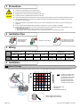
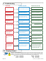
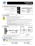
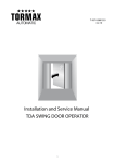
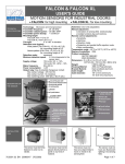
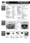
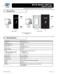
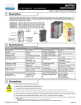
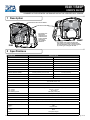
IS40 / IS40P USER’S GUIDE “The Peak Of Detection” COMBINED ACTIVE INFRARED / MICROWAVE AND ACTIVE INFRARED ONLY SENSOR 1 Description MICROWAVE FIELD ADJUSTMENT LED INDICATORS - The IS40 uses Microwave technology for activation and Active Infrared technology for presence detection. IS40P - The IS40P uses Active Infrared (IR) technology for presence detection only and the activation relay can be triggered by entering or exiting the IR field. IS40 2 Specifications DESCRIPTION TECHNOLOGY SPECIFICATION MICROWAVE (IS40 Only) INFRARED RADIATED FREQUENCY 24.175 GHz 875nm RADIATED POWER DENSITY < 5 mW/cm² < 250mW/m² Motion Motion & Presence 13’ x 16’ (4m x 5m) (10’ x 10’) 3m x 3m 0.5 sec. to 9 sec. 0.5 sec. 100ms 250ms 2 in/sec (5cm/sec) in sensor axis 0 in/sec (0cm/sec) Green Red DETECTION MODE MAXIMUM DETECTION FIELD OUTPUT HOLD TIME REACTION TIME MINIMUM TARGET SPEED LED SIGNAL ANTENNA TILT ANGLE SENSOR TILT ANGLE -8° to 22° (relative to sensor front face) N/A 15° to 45° SUPPLY VOLTAGE 12 to 24VAC ± 10% 12 to 24VDC +30% / -5% MAIN FREQUENCY 50 to 60Hz POWER CONSUMPTION RELAY OUTPUT - Max. Voltage - Max. Current - Max Switching Power < 2W 2 Relays with switch-over contact (voltage free) 60 VDC / 125 VAC 1A (resistive) 30W (DC) / 60VA (AC) INSTALLATION HEIGHT 8’ to 16’ (2.5m to 5m) TEMPERATURE RANGE -22°F ( -30°C) to + 140°F (60°C) PROTECTION DEGREE NORM CONFORMITY DIMENSIONS (D X W X H) MATERIAL - Housing - Face COLOR - Housing - Face CABLE LENGTH NEMA-4 Electromagnetic compatibility (EMC) according to 2004/108/EEC, R&TTE: 1999/5/EC 5 in. X 4 in. X 3.75 in. (127mm x 102mm x 96mm) ABS Polycarbonate Black Transparent Purple 32 feet (10m) 75.5371.01 EN 20080505 (75.5370) Page 1 of 6 3 Precautions This device IS NOT intended for use as a safety sensor. Shut off all power before attempting any wiring procedures. Maintain a clean & safe environment when working in public areas. Constantly be aware of pedestrian/vehicle traffic around the area. Always stop pedestrian/vehicle traffic through the doorway when performing tests that may result in unexpected reactions by the door. ESD electrostatic discharge: Circuit boards are vulnerable to damage by electrostatic discharge. Before handling any board ensure you dissipate your body’s charge. Always check placement of all wiring before powering up to insure that moving parts will not catch any wires and cause damage to equipment. Ensure compliance with all applicable safety standards (i.e. ANSI A156.10 / 19) upon completion of installation. DO NOT attempt any internal repair of the sensor. All repairs and/or component replacements must be performed by BEA Inc. Unauthorized disassembly or repair: 1. May jeopardize personal safety and may expose one to the risk of electrical shock. 2. May adversely affect the safe and reliable performance of the product will result in a voided product warranty. 4 Installation Tips The sensor must be firmly fastened to prevent vibration. The sensor must not have any object likely to move or vibrate in its sensing field. DO NOT cover the sensor. 5 Wiring POWER (VAC / DC) ACTIVATION RELAY PRESENCE RELAY LABEL COLOR 12-24 12-24 COM NO NC COM NO NC RED BLACK WHITE GREEN YELLOW WHITE W/BLACK STRIPE GREEN W/BLACK STRIPE YELLOW W/BLACK STRIPE 6 Installation 1 Sensor Tilt Angle It is important to adjust sensor angle first to position IR field correctly. Then adapt angle of radar field by using tilt angle adjustment screw. 20∞ 6.50 3.25 0 30∞ CEIL M OU NT G IN 3.25 6.50 ft. ft. 3.25 6.50 9.75 45∞ 30° 15° Page 2 of 6 NOTE: To obtain an IR pattern that’s straight down (closest to the door thershold); wall mounted sensors need to be set at 20º, while sensors that are extended out from the wall should be set at around 15º. 13.00 16.30 19.70 30° 15° W AL L MOUNT Mounting height: 16 ft. Sensitivity: 9 Microwave field angle: 30° When the angle of the sensor is chosen, tighten the screws firmly. 75.5371.01 EN 20080505 (75.5370) 2 Microwave Field Tilt Angle + By turning the tilt angle adjustment screw clockwise, the radar field angle is reduced. 6.50 - 3.25 0 3.25 MIN 6.50 ft ft 3.25 6.50 9.75 13.0 16.3 By turning the tilt angle adjustment screw counter clockwise, the radar field angle is increased. 19.7 23.0 Mounting height: 16 ft. Sensitivity: 9 Sensor angle: 20° MAX 26.3 7 Remote Control Functions Every programming session begins by unlocking the sensor. Thereafter a program setting may be altered by pressing the desired function key followed by the desired value for that function. When all programming is complete press the lock key twice to retain settings. Use the following as a guide: Unlock the sensor to enter into adjustment session (if no access code has been entered) To change the value of a parameter (ex. Automatic Learn Time) … to change any other parameters (ex. Relay Configuration) To check the value of a parameter (ex. Automatic Learn Time) Lock the adjustment session and go back to normal function Press Unlock Key RED LED Flashes Slowly 0-9 Select Parameter to Change RED LED Flashes Quickly Enter New Value RED LED Flashes Slowly 0-9 Select Parameter to Change RED LED Flashes Quickly Enter New Value Select Parameter to Check RED LED Flashes Quickly Press Question Mark RED LED Flashes Slowly ? OR The Number of Green Flashes Indicate the Value of This Parameter RED LED Flashes Slowly + Lock Code Press Lock Key Twice 75.5371.01 EN 20080505 (75.5370) Page 3 of 6 8 Setup & Startup 1 Setup Sequence 1. Power on the sensor. Sensor automatically performs a Setup on power up and Setup is complete when Red/Green flashing stops. 2. If the Detection Zone (Background) permanently changes and a new Setup is required, perform a new Setup by pressing 0 0 . Red & Green LEDs will blink rapidly until setup is complete. NOTE: Avoid movement in the IR zone during setup. 2 Remote Control Parameters FUNCTION AFFECTS INFRARED OR MICROWAVE REMOTE CONTROL BUTTON FUNCTION DESCRIPTION AUTOMATIC LEARN TIME INFRARED 0: 30 seconds 1: 1 minute 2: 2 minutes IMMUNITY INFRARED 1: Low (Normal) 2: Medium (Rain) 3: High (Snow) DOOR PATTERN INFRARED 6 DOOR DOOR 2 1 DOOR 7 8 DOOR DOOR 6 FREQUENCY 6: 60 minutes 9: ∞(Infinity) 3: 5 minutes 4: 10 minutes 5: 20 minutes DOOR 3 4 5 9 DOOR 8 7 DOOR 9 1: L - L’ Pulse Frequency 2: H - H’ Pulse Frequency INFRARED Define the Minimum Target Size 1: TARGET SIZE INFRARED F2 2: 6: 2x2 4: 3x3 2x3 4x4 7: 3: Page 4 of 6 1x1 5: 3x2 1x2 75.5371.01 EN 20080505 (75.5370) 2 Remote Control Parameters (Continued) FUNCTION AFFECTS INFRARED OR MICROWAVE REMOTE CONTROL BUTTON FUNCTION DESCRIPTION 6 3 0 3 6 FT. 3 6 SENSITIVITY 0 - 9: (7 - Default) MICROWAVE Height = 16 ft. Sensitivity 9, 6, 3 DETECTION MODE REJECTION MODE ACTIVATION RELAY HOLD TIME RELAY CONFIGURATION S=6 15 S=9 18 1: Bidirectional (Towards or Away from Sensors) 2: Unidirectional Approach (Towards Sensor) 3: Unidirectional Depart (Away from Sensor) MICROWAVE 1: Detection of all kind of Targets 4: Medium ‘Pedestrian/Parallel traffic’ in Motion Rejection + Interference Immunity 2: Detection of all kind of Targets in Motion 5: High ‘Pedestrian/Parallel traffic’ Rejection + Interference Immunity + Interference Immunity 3: Low ‘Pedestrian/Parallel traffic’ Rejection + Interference Immunity MICROWAVE 0: 1: 2: 3: 4: 0.5 second 1.0 second 2.0 seconds 3.0 seconds 4.0 seconds 5: 6: 7: 8: 9: Presence Relay Description Passive Detection INFRARED 1 Active MICROWAVE 2 Passive Active 3 Passive Passive 4 Active MICROWAVE DOOR EXAMPLE LAST LINE FIRST LINE INFRARED SETUP MICROWAVE INFRARED MICROWAVE Active Passive NO COM NO COM NC No Detection NC NO COM NO COM NC Active IS40 Activates when object is in presence zone. ACTIVATION RELAY INFRARED 5.0 seconds 6.0 seconds 7.0 seconds 8.0 seconds 9.0 seconds Activation Relay 0 - 4: ALL MODES DEFAULT VALUES 12 MICROWAVE PRESENCE RELAY OUTPUT CONFIGURATION 9 S=3 IS40 NC IS40P Activates when object is in presence zone. IS40P 0: STANDARD MODE Activates when motion detected. Activates when object is in presence zone. 1: PULSE ON ENTRY Activates if object motion is detected and then object enters presence zone. Activates when object enters presence zone. 2: PULSE ON EXIT Activates if object motion is detected and then object exits presence zone. Activaties when object exits presence zone. 3: PULSE ON ENTRY FIRST / LAST LINE (See Example to the Left) Activates if object motion is detected and then object enters presence zone (first or last line). Activates when object enters presence zone (first or last line). 4: PULSE ON EXIT FIRST / LAST LINE (See Example to the Left) Activates if object motion is detected and then object exits presence zone (first or last line). Activates when object exits presence zone (first or last line). F1 Initiate Setup, press To set Factory Defaults, press 0 9 75.5371.01 EN 20080505 (75.5370) Page 5 of 6 9 Troubleshooting POSSIBLE CAUSES SYMPTOMS CORRECTIVE ACTION Wait for learn time setting to expire. The red LED stays on. The sensor detects a presence. Launch a setup. The red LED is on during rain or snow. The presence detection is disturbed by the rain or snow. The green LED is on during rain or snow. The microwave detection is disturbed by the rain or snow. Increase the immunity of the IR field (value 2 or 3, respectively). Increase the mircowave rejection. Consider using unidirectional mode under the Detection Parameters. The red LED is permanently on after a setup. Setup has failed due to motion in the IR field. Launch a new setup with the IR area clear of moving objects. The door keeps recycling open-closed. Sensor detects door movement. Increase C h a n g e the sensor angle and/or Sensor detects door vibrations. Increase mircrowave rejection. The sensor detects objects outside of its detection field. Too much reflection due to a metallic environment. Increase the mircowave rejection. The sensor does not respond to the remote control. The batteries in the remote control are not installed properly or dead. Verify or replace the batteries. The remote control is poorly aimed. Point the remote control directly towards the sensor. The sensor is not powered. Check the power supply of the sensor. You must enter a code or the wrong code was entered. Cut and restore power supply. No code is required to unlock during the first minute after powering on. Unlock, then lock and ‘enter’ a new access code or 0000 to delete the current access code. Application requires an access code or sensor will not unlock after entering an access code. mircowave field angle. 10 Company Contact Do not leave problems unresolved. If a satisfactory solution cannot be achieved after troubleshooting a problem, please call BEA, Inc. If you must wait for the following workday to call BEA., leave the door inoperable until satisfactory repairs can be made. Never sacrifice the safe operation of the automatic door or gate for an incomplete solution. The following numbers can be called 24 hours a day, 7 days a week. For more information, visit www.beasensors.com. US and Canada: 1-866-249-7937 Canada: 1-866-836-1863 Northeast: 1-866-836-1863 Page 6 of 6 Southeast: Midwest: West: 1-800-407-4545 1-888-308-8843 1-888-419-2564 75.5371.01 EN 20080505 (75.5370)