1
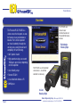
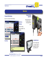
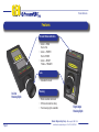
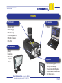
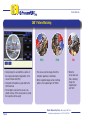
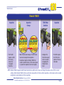
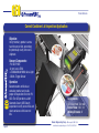
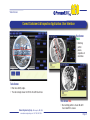
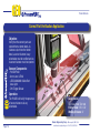
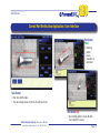
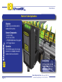
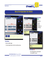
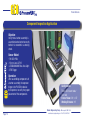
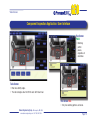
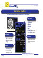
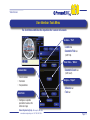
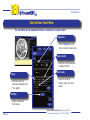
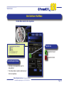
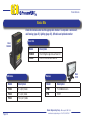
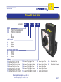
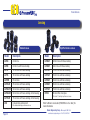
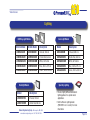
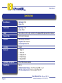
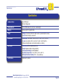
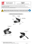
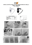
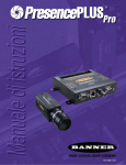
Field Guide
Featuring the
PresencePLUS® P4
GEO
Vision Sensor
Vision Sensors
Overview
The P4 GEO uses
the same user
interface found in all
PresencePLUS vision
sensors.
The PresencePLUS P4 GEO is a
vision sensor that inspects an area
for features in any orientation or
location. Parts to be inspected
can travel randomly through the
sensing area, saving the cost and
complexity of hard fixturing.
Right-Angle
Housing Style
• 360° pattern match
• High-speed sensing; can exceed
1500 parts per minute, depending
on the inspection
• User-friendly setup
• Remote TEACH
The P4 GEO is a self-contained
vision sensor – no external
controller is necessary.
• Live video feed without a PC
• $995 price
In-Line
Housing Style
Banner Engineering Corp. • Minneapolis, MN USA
Page 2
www.bannerengineering.com • Tel: 763.544.3164
Vision Sensors
Overview
Remote TEACH
Capability
PresencePLUS Software
Easy to use; requires minimal training
360° Part
Rotation
After initial setup, the
P4 GEO can learn a
new target without
a PC.
Senses moving
parts traveling in any
position
Live Video Feed
Tools Menu
The P4 GEO provides
a live video output, to
display the sensing
area without a PC.
Run Menu
Banner Engineering Corp. • Minneapolis, MN USA
www.bannerengineering.com • Tel: 763.544.3164
Page 3
Vision Sensors
Features
Bi-Color Status Indicators
• Green = PASS
Red = FAIL
• Green = POWER
Red = ERROR
• Green = READY
Yellow = TRIGGER
Lens
• Standard C-mount
In-Line
Housing Style
Housing
• Black anodized aluminum
• IP20 environmental rating
• Two housing styles available
Right-Angle
Housing Style
Banner Engineering Corp. • Minneapolis, MN USA
Page 4
www.bannerengineering.com • Tel: 763.544.3164
Vision Sensors
Features
12-Pin Discrete I/O
PC Connection
•
•
•
•
•
•
• Ethernet
Remote TEACH
External Trigger
Product Change
4 user-configurable I/O
RS-232 connections
10-30V dc
NTSC Video Monitor
(Optional)
• Live images
• Holds failed
inspection
images
Light Source
• Choose from ring lights,
area lights and backlights
• Infrared and visible LED options
• Strobe option via sensor software
• 24V dc; see page 25
Banner Engineering Corp. • Minneapolis, MN USA
www.bannerengineering.com • Tel: 763.544.3164
Page 5
Vision Sensors
360° Pattern Matching
PASS
• During Setup, the user identifies a section of
the image containing the target pattern in the
sensor’s field of view (FOV).
• A template of the pattern is generated for the
GEO Count tool.
• The template is stored in the sensor’s nonvolatile memory. (If the sensor power is cycled,
the inspection will be saved.)
PASS
• The sensor searches images to find the
template, regardless of orientation.
• When inspected images contain matching
patterns, the inspected part will “PASS.”
FAIL
• When the
sensor does not
find a matching
image, the
inspected part
will “FAIL.”
Banner Engineering Corp. • Minneapolis, MN USA
Page 6
www.bannerengineering.com • Tel: 763.544.3164
Vision Sensors
Remote TEACH
Inspection
• The P4 GEO
inspects an ROI
for missing,
incorrect or
“smudged”
characters.
Inspection
Change
TEACH New
Condition
Inspection
• When the date code changes, the GEO Count
tool must be taught the new pattern.
• Inspections taught via Remote TEACH are
saved in volatile memory. (If the sensor power
is cycled, the inspection must be re-taught.)
• Configure the
P4 GEO to inspect
for the new date
by toggling the
Remote Teach
input.
• The GEO inspects
the FOV for the
pattern of the new
date code.
NOTE: Remote TEACH changes the GEO Count tool reference pattern only; it does not change the exposure time, ROI, or sensor
settings. When Remote TEACH will be used to teach new patterns for future similar inspections, initial setup must be carefully
configured to accommodate all of the inspections.
Banner Engineering Corp. • Minneapolis, MN USA
www.bannerengineering.com • Tel: 763.544.3164
Page 7
Vision Sensors
Correct Container Lid Inspection Application
Objective:
Verify that dairy product cartons
have the correct lids, preventing
the potentially costly return of a
shipment.
Sensors/Components:
- P4 GEO P4GR
- 8 mm Lens LCF08
- LEDWA80X80M White Area Light
- QS30L Trigger Sensor
Operation:
Barcode reader verifies base
container product and recalls
proper lid inspection file in the P4
GEO. The GEO performs a 360°
Geometric Count (GEO Count)
inspection to verify correct lids and
reject containers with incorrect
lids.
Configuration:
GEO Count tool/Test tool
Field of View: 1.8" x 1.3"
Working Distance: 6"
Banner Engineering Corp. • Minneapolis, MN USA
Page 8
www.bannerengineering.com • Tel: 763.544.3164
Vision Sensors
Correct Container Lid Inspection Application: User Interface
Run Screen
PASS
• Matching
pattern
passes,
regardless of
orientation.
Tools Screen
• Blue lines identify edges.
• The red rectangle shows the ROI for the GEO Count tool.
Run Screen FAIL
Banner Engineering Corp. • Minneapolis, MN USA
www.bannerengineering.com • Tel: 763.544.3164
• No matching pattern is found. No GEO
Count tool ROI is shown.
Page 9
Vision Sensors
Correct Part Verification Application
Objective:
Verify that the correct parts are
ejected from a feeder bowl. As
fasteners eject from the feeder
bowl, a correct fastener in any
orientation must be verified and an
incorrect fastener must be rejected.
Sensors/Components:
- P4 GEO P4GI
- 8 mm Lens LCF08
- LEDRA80X80M Visible Red
Area Light
- D10 Trigger Sensor
Operation:
The P4 GEO will verify the presence
of correct fasteners in any
orientation.
Configuration:
GEO Count tool/Test tool
Field of View: 1.0" x 0.8"
Working Distance: 3"
Banner Engineering Corp. • Minneapolis, MN USA
Page 10
www.bannerengineering.com • Tel: 763.544.3164
Vision Sensors
Correct Part Verification Application: User Interface
Run Screen
PASS
• Matching
pattern
passes,
regardless of
orientation.
Tools Screen
• Blue lines identify edges.
• The red rectangle shows the ROI for the GEO Count tool.
Run Screen FAIL
Banner Engineering Corp. • Minneapolis, MN USA
www.bannerengineering.com • Tel: 763.544.3164
• No matching pattern is found. No GEO
Count tool ROI is shown.
Page 11
Vision Sensors
Date Lot Code Application
Objective:
Inspect the current date and lot
codes on film cartons
Sensors/Components:
- P4 GEO P4GR
- 8 mm Lens LCF08
- LEDGR62X62M Green Ring Light
- D10 Trigger Sensor
Operation:
The P4 GEO inspects for missing,
incorrect or smudged characters.
Cartons that fail are diverted.
Configuration:
GEO Count tool/Test tool
Field of View: 0.8" x 0.5"
Working Distance: 2.5"
Banner Engineering Corp. • Minneapolis, MN USA
Page 12
www.bannerengineering.com • Tel: 763.544.3164
Vision Sensors
Date Lot Code Application: User Interface
Run Screen
PASS
• Matching
pattern
passes,
regardless of
orientation.
Tools Screen
• Blue lines identify edges.
• The red rectangle shows the ROI for the GEO Count tool.
Run Screen FAIL
Banner Engineering Corp. • Minneapolis, MN USA
www.bannerengineering.com • Tel: 763.544.3164
• No matching pattern is found. No GEO
Count tool ROI is shown.
Page 13
Vision Sensors
Component Inspection Application
Objective:
Verify that a button assembly is
assembled and oriented correctly
before it is mounted in a steering
wheel.
Sensor Model:
- P4 GEO P4GI
- 12 mm Lens LCF12
- LEDBA80X80M Blue Area Light
- OTB Trigger
Operation:
After assembling components of
a button assembly, the operator
triggers the P4 GEO to look at
three patterns to verify the proper
placement of the components.
Configuration:
Three GEO Count tools/
Test tool
Field of View: 2.0" x 1.5"
Working Distance: 10"
Banner Engineering Corp. • Minneapolis, MN USA
Page 14
www.bannerengineering.com • Tel: 763.544.3164
Vision Sensors
Component Inspection Application: User Interface
Run Screen
PASS
• Matching
pattern
passes,
regardless of
orientation.
Tools Screen
• Blue lines identify edges.
• The red rectangles show the ROI for each GEO Count tool.
Run Screen FAIL
• Only two matching patterns are found.
Banner Engineering Corp. • Minneapolis, MN USA
www.bannerengineering.com • Tel: 763.544.3164
Page 15
Vision Sensors
User Interface: Setup Menu
The Setup Menu captures a reference image and sets the trigger options.
Trigger Options
• Continuous
• Manual
• External
• OFF
• Trigger triggers the sensor
when Manual is selected
Auto Exposure
• Start sets exposure value
• Undo reverts to previous
setting
Focus Value
• Number between 1 and 255
based on the contrast of the
image
Exposure
• Time Setting and Gain
• Used to control the
brightness of the image
Page 16
Banner Engineering Corp. • Minneapolis, MN USA
www.bannerengineering.com • Tel: 763.544.3164
Vision Sensors
User Interface: Tools Menu
The Tools Menu establishes the inspections that a sensor will execute.
Location – “Find”
• Locate tool
• Geometric Find tool
(GEO Find)
Vision Tools – “Define”
Communication
• Geometric Count tool
(GEO Count)
• Communication
• Tool labels
• Tool parameters
Analysis – “Report”
Quick Teach
• Test tool
• Measure tool
• Configures inspection
parameters based on the
reference image
Banner Engineering Corp. • Minneapolis, MN USA
www.bannerengineering.com • Tel: 763.544.3164
Page 17
Vision Sensors
User Interface: Teach Menu
The Teach Menu sets the judgment tolerances of inspections on a good product.
Sample Size
• Use the Count option when
there is a known sample set size
Capture Control
• Determine how the information
is updated to the PC
Display
• Determines when the
information displayed on the
PC is updated
Teach Counts
• Tracks the number of
samples used in each Teach
process
Start/Stop
• Initiates and stops the
Teach process
Banner Engineering Corp. • Minneapolis, MN USA
Page 18
www.bannerengineering.com • Tel: 763.544.3164
Vision Sensors
User Interface: Run Menu
The Run Menu monitors the inspections.
Pass/Fail Icon
Inspection Passed
Inspection Failed
Results/Navigation Window
• Each tool can be expanded to show the
data collected
• The window helps to quickly troubleshoot and
fine-tune inspections
Banner Engineering Corp. • Minneapolis, MN USA
www.bannerengineering.com • Tel: 763.544.3164
Page 19
Vision Sensors
Basic Kits
Basic kits include sensor and the appropriate bracket. To complete a solution kit,
add lensing (page 22), lighting (page 23), QD cable and optional monitor.
Basic Kits
Model
P4GRKB
QD Cables
Model
Description
P4GRKB
P4 GEO Right-Angle Sensor Basic Kit
P4GIKB
P4 GEO In-line Sensor Basic Kit
Model
PPM7
Monitors
Model
Description
Model
Description
P4C06
2 m (6.5') Cable
PPM7
7" LCD Wide Screen
P4C23
7 m (23') Cable
PPM
9" CRT
P4C32
10 m (32') Cable
Banner Engineering Corp. • Minneapolis, MN USA
Page 20
www.bannerengineering.com • Tel: 763.544.3164
Vision Sensors
Solution Kit Model Matrix
EXAMPLE: P4GR
Sensor
P4GR P4 GEO Right-Angle Sensor
P4GI
P4 GEO In-Line Sensor
K
Kit
B
Bracket
Cable Length
06
6 feet
23
23 feet
32
32 feet
Lens Focal Length in mm
08
8 mm
12
12 mm
16
16 mm
Lighting
LRR
SRR Small Ring Light Red
LRW
SRW Small Ring Light White
LRB
SRB Small Ring Light Blue
LRG
SRG Small Ring Light Green
SRI Small Ring Light Infrared LRI
K
B
23
12 SRR
Large Ring Light Red
Large Ring Light White
Large Ring Light Blue
Large Ring Light Green
Large Ring Light Infrared
AR
AW
AB
AG
AI
Area Light Red
BR
Area Light White BI
Area Light Blue
Area Light Green
Area Light Infrared
Backlight Red
Backlight Infrared
Banner Engineering Corp. • Minneapolis, MN USA
www.bannerengineering.com • Tel: 763.544.3164
Page 21
Vision Sensors
Lensing
Standard Lenses
Model
Description
LCF04
LCF08
High-Performance Lenses
Model
Description
4 mm lens
LCF06LT
6.5 mm lens with focus locking
8 mm lens with focus locking
LCF08LT
8 mm lens with focus locking
LCF12
12 mm lens with focus locking
LCF12LT
12 mm lens with focus locking
LCF16
16 mm lens with focus locking
LCF16LT
16 mm lens with focus locking
LCF25R
25 mm lens
LCF25LT
25 mm lens with focus locking
LCF25LR
25 mm lens with focus locking
LCF50LT
50 mm lens with focus locking
LCF50L1R
50 mm lens with focus locking
LCF75LT
75 mm lens with focus locking
LCF50L2R
50 mm lens with focus locking, metal housing
FLTUV
UV lens filter, clear glass
LCF75LR
75 mm lens with focus locking, metal housing
LEK
C-mount lens extension kit
Fits standard and high-performance lenses.
Fits 8 mm-75 mm high-performance lenses.
Refer to Banner Lens Guide (P/N 69950 rev. C or later) for
more information
Banner Engineering Corp. • Minneapolis, MN USA
Page 22
www.bannerengineering.com • Tel: 763.544.3164
Vision Sensors
Lighting
LED Ring Light Models
Area Light Models
62 mm Model
80 mm Model
Description
Model
Description
LEDIR62X62M
LEDIR80X80M
Infrared, 940 nm
LEDIA80X80M
Infrared, 850 nm
LEDRR62X62M
LEDRR80X80M
Visible Red, 630 nm
LEDRA80X80M
Visible Red, 630 nm
White, All Visible
LEDWR62X62M
LEDWR80X80M
White, All Visible
LEDWA80X80M
LEDBR62X62M
LEDBR80X80M
Blue, 464 to 475 nm
LEDBA80X80M
Blue, 464 to 475 nm
LEDGR62X62M
LEDGR80X80M
Green, 520 to 540 nm
LEDGA80X80M
Green, 520 to 540 nm
Backlight Models
Specialty Lighting
Model
Description
LEDIB70X70M
Infrared, 940 nm
LEDRB70X70M
Visible Red, 660 nm
Banner Engineering Corp. • Minneapolis, MN USA
www.bannerengineering.com • Tel: 763.544.3164
• On-axis, highly diffused and indirect
lighting options for special-needs
applications
• Refer to Banner Lighting Guide
(P/N 69951 rev. C or later) for more
information
Page 23
Vision Sensors
Specifications
Model Numbers
Right-Angle: P4GR
In-Line: P4GI
Part Numbers
Right-Angle: 71431
In-Line: 71432
Imager
2.56 x 2.06 mm (0.10" x 0.08"), 3.25 mm (0.13") diagonal CMOS; pixel size 20 x 20 microns
Exposure Time
0.01 to 20.47 milliseconds
Acquisition
500 frames per second max.
Image Size: 128 x 100 pixels
Levels of Gray Scale: 256
Lens Mount
C-mount
Discrete I/O
1
1
4
1
1
Input/Output Configuration
NPN or PNP software selectable
Output Rating
150 mA
ON-State Saturation Voltage: <1V at 150 mA max NPN; >V ± 2V
OFF-State Leakage Current: <100 microamps NPN or PNP
Trigger IN
Strobe OUT
Configurable I/O
Product Change
Remote TEACH
Banner Engineering Corp. • Minneapolis, MN USA
Page 24
www.bannerengineering.com • Tel: 763.544.3164
Vision Sensors
Specifications
Communication
RJ-45 Ethernet
RS-232 flying leads
Display Options
PC or NTSC video (9 m [30'] max. cable length)
Memory
Stores up to 12 inspection files
Power
Voltage: 10-30V dc (24V dc if a light source is powered by the sensor)
Current: 500 milliamps, maximum
Dimensions
Right-Angle: 55.6 x 66.8 x 124.5 mm (4.9" x 2.63" x 2.2") H x W x L
In-Line: 34.3 x 66.8 x 147.3 mm (1.35" x 2.63" x 5.8") H x W x L
(Measured length does not include connectors or cables.)
Mechanical
Construction: Black anodized aluminum
Weight: Approximately 0.29 kg (0.642 lb.)
Environmental Rating: IEC IP20; NEMA 1
Operating Temperature: 0° to +50°C (+32° to +122° F)
Maximum Relative Humidity: 90%, non-condensing
Certifications
Approvals in process
Banner Engineering Corp. • Minneapolis, MN USA
www.bannerengineering.com • Tel: 763.544.3164
Page 25
Vision Sensors
Hardware
Model
Imager
Technology
Imager
Size
Housing
Style
Lensing
Options
CCD
640 x 480
In-line
CMOS
128 x 100
CMOS
512 x 384
Live Video
Communication
Discrete I/O
Standard
C-Mount
NTSC
Ethernet
RS-232C
6 Configurable
Functional
Timing
In-line or
Right-Angle
Standard
C-Mount
NTSC
Ethernet
RS-232C
4 Configurable
Functional
Timing
Right-Angle
Standard
C-Mount
N/A
RS-232C
3 Configurable
Functional
Timing
Banner Engineering Corp. • Minneapolis, MN USA
Page 26
www.bannerengineering.com • Tel: 763.544.3164
Vision Sensors
Software
Model
User Interface
Menu-Driven
Location/Rotation
Adjustment
Locate
(+/–) 90° Rotation
Pattern Find
(+/–) 10° Rotation
Vision Tools
Pattern Count
BLOB
Edge
Object
Average Grey
Locate
Menu-Driven
Menu-Driven
GEO Find
(+/–) 360° Rotation
N/A
GEO Count
Pixel Count
Analysis
Measurement
Test
Measurement
Test
N/A
Inspection
Configuration
Multiple Inspections
Manual
Quick TEACH
TEACH
12 Inspections –
Remotely Selectable
Manual
Quick TEACH
TEACH
Remote TEACH
12 Inspections –
Remotely Selectable
Manual
Quick TEACH
TEACH
4 Inspections –
Manually Selectable
from Optional Hand-Held
Controller
Banner Engineering Corp. • Minneapolis, MN USA
www.bannerengineering.com • Tel: 763.544.3164
Page 27
For additional information...
Lighting Guide
P/N 69951 rev. C or later
Quick Start
P/N 118000
User’s Manual
P/N 117020
Lens Selection Guide
P/N 69950 rev. C or later
Printed in USA
06/04
P/N 118000
•
PresencePLUS Software
P/N 72806
9714 10th Avenue North • Minneapolis, MN 55441 • Phone: 763-544-3164 • www.bannerengineering.com
p/n 117998