1
AVWorks™
Installer/User Guide
INSTRUCTIONS
This symbol is intended to alert the user to the presence of important operating and
maintenance (servicing) instructions in the literature accompanying the appliance.
AVWorks™
Installer/User Guide
Avocent, the Avocent logo, The Power of Being There and AVWorks
are trademarks of Avocent Corporation. OSCAR is a registered
trademark of Apex Inc. AutoView is a registered trademark of Cybex
Computer Products Corporation. All other marks are trademarks or
registered trademarks of their respective owners.
© 2003 Avocent Corporation. All rights reserved.
Table of Contents
Chapter 1: Product Overview
About AVWorks . . . . . . . . . . . . . . . . . . . . . . . . . . . . . . . . . 3
Features and Benefits . . . . . . . . . . . . . . . . . . . . . . . . . . . . . 3
Chapter 2: Installation
Getting Started . . . . . . . . . . . . . . . . . . . . . . . . . . . . . . . . . . 7
Installing AVWorks . . . . . . . . . . . . . . . . . . . . . . . . . . . . . 7
Chapter 3: Basic Operations
Launching AVWorks . . . . . . . . . . . . . . . . . . . . . . . . . . . .
Navigating AVWorks . . . . . . . . . . . . . . . . . . . . . . . . . . . .
Appliance/AVWorks Quick Setup Checklist . . . . . . . . . .
Adding an Appliance . . . . . . . . . . . . . . . . . . . . . . . . . . . .
Accessing an Appliance . . . . . . . . . . . . . . . . . . . . . . . . . .
Accessing and Managing Your Devices . . . . . . . . . . . . .
Changing AVWorks Device Properties . . . . . . . . . . . . . .
Organizing Units with the Local Client Database . . . .
Deleting and Renaming . . . . . . . . . . . . . . . . . . . . . . . . .
Customizing the AVWorks Explorer Window . . . . . . . .
Managing Your Local Databases . . . . . . . . . . . . . . . . . .
11
11
13
14
17
19
33
36
41
43
44
Chapter 4: Managing Your Appliance
Viewing and Configuring Appliance Parameters . . . . .
Upgrading Firmware . . . . . . . . . . . . . . . . . . . . . . . . . . .
Managing User Sessions . . . . . . . . . . . . . . . . . . . . . . . . .
Rebooting Your Appliance . . . . . . . . . . . . . . . . . . . . . . .
Managing Appliance Configuration Databases . . . . . .
Managing User Databases . . . . . . . . . . . . . . . . . . . . . . .
Changing Appliance Properties . . . . . . . . . . . . . . . . . . .
Adding and Deleting Product Licenses . . . . . . . . . . . . .
50
58
61
61
62
62
63
66
Appendices
Appendix A: Updating AVWorks . . . . . . . . . . . . . . . . . .
Appendix B: Keyboard and Mouse Shortcuts . . . . . . . .
Appendix C: Sun Advanced Key Emulation . . . . . . . . .
Appendix D: TCP Ports . . . . . . . . . . . . . . . . . . . . . . . . . .
Appendix E: Troubleshooting . . . . . . . . . . . . . . . . . . . . .
Appendix F: Technical Support . . . . . . . . . . . . . . . . . . .
69
70
72
73
74
75
Index
Index . . . . . . . . . . . . . . . . . . . . . . . . . . . . . . . . . . . . . . . . . 79
1
Product Overview
Contents
About AVWorks . . . . . . . . . . . . . . . . . . . . . . . . . . . . . . . . . 3
Features and Benefits . . . . . . . . . . . . . . . . . . . . . . . . . . . . . 3
Chapter 1: Product Overview
3
Chapter 1: Product Overview
About AVWorks
AVWorks is a cross-platform management application that allows you to view
and control the AutoView 1000R/2000R appliance and all its target devices. The
cross-platform design ensures compatibility with most popular operating
systems and hardware platforms. AutoView 1000R provides secure switch-based
authentication, data transfers and username/password storage. Each appliance
handles authentication and access control individually, placing system control at
the point of need.
AVWorks utilizes browser-like navigation with an intuitive split-screen
interface, providing you with a single point of access for all your servers. Using
AVWorks, you can manage your existing appliances, install a new switch or
launch a video session to a target device. Built-in groupings such as Devices,
Sites and Folders provide an easy way to select the units to view. Powerful
search and sort capabilities allow you to easily find any unit.
NOTE: Throughout the documentation and AVWorks user interface, you will see the word
“appliance” used generically to describe the AutoView 1000R/2000R switch.
Features and Benefits
Easy to install and configure
AVWorks is designed for easy installation and operation. Auto-discovery of
managed appliances enables you to deploy new units in minutes. Wizardbased installation and online help simplify initial system configuration. The
intuitive graphical interface makes managing and updating appliances simple
and straightforward.
Powerful customization capabilities
Tailor AVWorks to fit your specific system needs. Take advantage of built-in
groups or create your own. Customize unit and field names, icons and macros
for maximum flexibility and convenience. Using names that are meaningful to
you makes it easy to quickly find any target device.
Extensive AutoView 1000R/2000R management
AVWorks allows you to add and manage multiple appliances in one system.
Once a new appliance is installed, you can configure switch parameters,
control and preempt user video sessions and execute numerous control
functions, such as rebooting and upgrading your appliance. From the intuitive
Appliance Management Panel, you can enable Simple Network Management
Protocol (SNMP) traps, configure target devices and cascade switches as well
as manage user databases.
4
AVWorks Installer/User Guide
2
Installation
Contents
Getting Started . . . . . . . . . . . . . . . . . . . . . . . . . . . . . . . . . 7
Installing AVWorks . . . . . . . . . . . . . . . . . . . . . . . . . . . . 7
Chapter 2: Installation
7
Chapter 2: Installation
Getting Started
Before installing your AVWorks, refer to the following lists to ensure that you
have all the items that shipped with your software as well as all other items
necessary for proper installation.
Supplied with AVWorks
Your AVWorks package contains the following items:
•
AVWorks CD
•
AVWorks Installer/ User Guide
•
Download Instructions
Supported operating systems
AVWorks is supported on the following operating systems:
•
Microsoft® Windows® 2000 Workstation - Service Pack 2
•
Microsoft Windows 2000 Server - Service Pack 2
•
Microsoft Windows NT® 4.0 Workstation - Service Pack 6a
•
Microsoft Windows NT 4.0 Server - Service Pack 6a
•
Microsoft Windows XP (Home and Professional)
•
Red Hat Linux® 7.1 (2.7 Kernel)
•
Red Hat Linux 7.2 (2.7 Kernel)
PC hardware configuration requirements
AVWorks is supported on the following minimum PC hardware configurations:
•
500 MHz Pentium III
•
128 MB RAM
•
10 or 100 BaseT NIC
•
XGA Video with graphics accelerator
•
Desktop size must be a minimum of 800 x 600
•
Color palette must be a minimum of 256 colors
Installing AVWorks
AVWorks can be installed on Microsoft Windows NT, Windows 2000, Windows
XP and Linux platforms. The following instructions will allow you to install
AVWorks on the desired platform.
8
AVWorks Installer/User Guide
To install on Microsoft Windows NT, 2000 or XP:
1.
Insert the AVWorks CD-ROM into your CD-ROM drive. If AutoPlay is
supported and enabled, the setup program will start automatically.
-orIf your system does not support AutoPlay, set the default drive to your
CD-ROM drive letter and execute the following command to start the
install program (replace drive with your CD-ROM drive letter):
drive:\WIN32\SETUP.EXE
2.
Follow the on-screen instructions.
To install on Red Hat Linux:
1.
Insert the AVWorks CD-ROM into your CD-ROM drive. If AutoPlay is
supported and enabled, the setup program will start automatically.
-orIf your system does not support AutoPlay:
a.
Mount the CD-ROM volume by executing the following command:
mount –t iso9660 –ro mode=0555 <unit> <mount point>
Replace <unit> with the name of the CD-ROM on your machine
and < mount point> with the name of the desired mount point. For
example, to mount a CD-ROM which is the second IDE unit on
/mnt, execute the command:
mount –t iso9660 –ro mode=0555 /dev/hdb /mnt
2.
b.
Execute the following command to change the working directory to
the mount point:
cd /mnt
c.
Execute the following command to start the install program:
sh./linux/setup.bin
Follow the on-screen instructions.
3
Basic Operations
Contents
Launching AVWorks . . . . . . . . . . . . . . . . . . . . . . . . . . . .
Navigating AVWorks . . . . . . . . . . . . . . . . . . . . . . . . . . . .
Appliance/AVWorks Quick Setup Checklist . . . . . . . . . .
Adding an Appliance . . . . . . . . . . . . . . . . . . . . . . . . . . . .
Accessing an Appliance . . . . . . . . . . . . . . . . . . . . . . . . . .
Accessing and Managing Your Devices . . . . . . . . . . . . .
Changing AVWorks Device Properties . . . . . . . . . . . . . .
Organizing Units with the Local Client Database . . . .
Deleting and Renaming . . . . . . . . . . . . . . . . . . . . . . . . .
Customizing the AVWorks Explorer Window . . . . . . . .
Managing Your Local Databases . . . . . . . . . . . . . . . . . .
11
11
13
14
17
19
33
36
41
43
44
Chapter 3: Basic Operations
11
Chapter 3: Basic Operations
Launching AVWorks
To launch AVWorks on all Microsoft Windows operating systems:
Select Start - Programs - Avocent AVWorks.
-orDouble-click the AVWorks icon. AVWorks will launch.
To launch AVWorks on Red Hat Linux (7.1 and 7.2):
From the application folder (/usr/lib/Avocent_AVWorks/), execute the
following command:
./Avocent_AVWorks
-orFrom (/user/bin), execute the following link:
./Avocent_AVWorks
-orIf a desktop shortcut was created on installation, double-click the shortcut.
AVWorks will launch.
Navigating AVWorks
AVWorks consists of several components: the AVWorks Explorer, the Video
Session Viewer (Viewer) and the Appliance Management Panel (AMP). Once
you launch AVWorks, the main AVWorks Explorer window appears. The
AVWorks Explorer window allows you to view, access, manage and create
custom groupings for all of the supported units in your data center.
When you select a target device, you can click the Connect Video task button in
the AVWorks Explorer to launch the Viewer. This component allows you to
control the keyboard, monitor and mouse functions of individual servers. For
more information, see Accessing and Managing Your Devices in this chapter.
When you select an appliance, you can click the Manage appliance task button
in the AVWorks Explorer to launch the AMP. This component enables you to
configure and control your appliance. For more information, see Chapter 4.
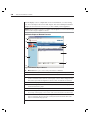
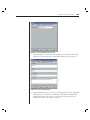
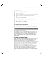
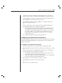
Viewing your system in the AVWorks Explorer
The AVWorks Explorer is divided into several panes: the View Selector tabs,
the Group Selector pane and the Unit Selector pane. The content of these panes
will change based on the type of unit selected or the task to be completed.
Figure 3.1 highlights these navigation features.
Click one of the View Selector tabs to view your system organized by
categories: Appliances, Devices, Sites or Folders. The AVWorks Explorer’s
12
AVWorks Installer/User Guide
default display is user-configurable. For more information, see Customizing
the AVWorks Explorer Window in this chapter. The AVWorks Explorer default
display is set for the Server view once you have added your first appliance.
NOTE: The Group Selector pane does not appear under the Appliances or Devices tab unless you
have more than one type of appliance or device.
AVWorks Explorer Window Features
A
B
F
G
C
H
D
I
E
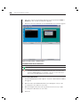
Figure 3.1: AVWorks Explorer Window
A.
Menu bar: Allows you to access many of the features in AVWorks.
B.
View Selector: Contains four View Selector tabs for choosing the AVWorks Explorer view.
C.
Root node: Each tree consists of a root node and branches.
D.
Group Selector pane: Contains a tree view representing the groups that are available
for the current View Selector tab. The selected group controls what is displayed in the
Unit Selector pane when the Appliances, Devices, Sites or Folder tabs are selected.
E.
Status bar: Displays the number of units shown in the Unit list.
F.
Unit Selector pane: Contains the Search bar, Unit list and Task buttons appropriate
for the selected view or group.
G.
Search bar: Allows you to search the database for the text entered in the search box.
H.
Unit list: Displays a list of servers, appliances and other selectable devices contained in
the currently selected group, or the results of the search executed from the Search bar.
I.
Task buttons: Contains buttons representing tasks that can be executed. Some
buttons are dynamic based on the type of unit(s) selected in the Unit list while other
buttons are fixed and always present.
Chapter 3: Basic Operations
13
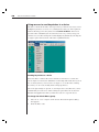
Appliance/AVWorks Quick Setup Checklist
The following list is an overview of the steps you will follow to set up and configure
your AutoView system. Each of these steps is explained in detail in separate topics
throughout this and the AutoView 1000R/2000R Installer/User Guide.
To set up the AutoView 1000R/2000R: (See the AutoView 1000R/2000R
Installer/ User Guide)
1.
Adjust mouse acceleration on each server to Slow or None.
2.
Install the AutoView 1000R/2000R hardware, connect the AVRIQ adaptors
and connect the keyboard, monitor and mouse to the analog port.
3.
Connect a terminal to the configuration (serial or 101 notation) port on the back
panel of the AutoView and set up network configuration (set network speed and
address type). The IP address can be set from AVWorks.
4.
Using the local analog workstation, input all server names via the OnScreen Configuration and Activity Reporting interface (OSCAR).
To set up AVWorks: (See this installer/user guide)
1.
Install AVWorks on each AVWorks client.
2.
From one AVWorks client, launch AVWorks.
3.
Click the New Appliance task button to add the new switch to the AVWorks
database. The New Appliance Wizard appears. If you configured the IP
address as described above, select Yes, the product already has an IP
address, otherwise select No, the product does not have an IP address.
AVWorks will find the appliance and all AVRIQ adaptors attached to it.
These names will display in the AVWorks Explorer.
4.
Set properties and group servers as desired into locations, sites or folders
through the AVWorks Explorer.
5.
Create user accounts through the AMP.
6.
Once one AVWorks client is set up, select File - Database - Save to save a
copy of the database with all the settings.
7.
From the second AVWorks client , click File - Database - Load and browse
to find the file you have saved. Select the file and click Load.
8.
If the local analog workstation (via OSCAR) adds, deletes or renames any
AVRIQ adaptors after you have loaded this file, you can resynchronize
your local database with OSCAR by clicking the Manage Appliance task
button and clicking the Resync button under Settings - Devices.
9.
To access a server attached to your AutoView 1000R/2000R, select the
desired server in the AVWorks Explorer and click the Connect Video task
button to launch a server session in the Video Session Viewer.
10. Adjust the resolution (select View - Auto Scale) and quality (select Tools Automatic Video Adjust) of the server video in the Video Session Viewer.
14
AVWorks Installer/User Guide
Adding an Appliance
Before you can access your appliance through AVWorks, you must add it to the
AVWorks database. Once an appliance is added, it appears in the Unit list. You
may either manually add or discover an appliance.
To manually add an appliance with an assigned IP address:
1.
Select File - New - Appliance from the AVWorks Explorer menu.
-orClick the New Appliance task button. The New Appliance Wizard appears.
Click Next to continue.
2.
Select the type of appliance you are adding. Click Next.
3.
You are prompted to indicate whether the appliance has an assigned IP
address or not. Click Yes, then click Next.
4.
The Find AutoView 1000R/2000R window appears. Type the IP address
and click Next.
5.
AVWorks will search for the indicated unit as well as all the powered
AVRIQs and server names you associated with it in OSCAR, if any. If you
want to search for unpowered AVRIQs, you can access the Resync feature
under the Devices category in the AMP and click the Include Offline
AVRIQ adaptors checkbox. For more information, see Viewing server
connections in Chapter 4. Click Next.
6.
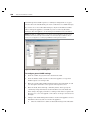
The Configure Cascade Switches dialog box appears if AVWorks detects an
attached legacy KVM switch such as an OutLook ES or AutoView 200 or
400 series switch. This box contains a list of all AVRIQ adaptor EIDs
(Electronic Identification Numbers) retrieved from the appliance and the
cascade switches to which they are connected, if any. When this dialog
box first displays, all the switches will be set to None. Switches detected
will have an icon next to the pulldown menu.
a.
b.
The Existing Cascade Switches field contains all the current switches
defined in the database. Click Add, Delete or Modify to alter the list.
Associate the appropriate switch from the pulldown menus for each
AVRIQ that has a switch attached.
Chapter 3: Basic Operations
15
Figure 3.2: Configure Cascade Switches Dialog Box
7.
When you reach the final page of the Wizard, click Finish to exit the
Wizard and return to the main window. Your appliance should now
appear in the Unit Selector pane.
To manually install a new appliance with no assigned IP address:
1.
Select File - New - AutoView 1000R/2000R from the AVWorks Explorer menu.
-orClick the New Appliance task button. The New Appliance Wizard appears.
Click Next to continue.
2.
You are prompted to indicate if the AutoView 1000R/2000R has an
assigned IP address. Click No and then click Next.
3.
The Network Address window appears. Type the IP address, subnet mask
and gateway that you want to assign to the unit and click Next.
4.
The Select AutoView 1000R/2000R window appears, prompting you to
select the unit to add from the list of new appliances that were found.
Select the unit and then click Next.
5.
The Configuring AutoView 1000R/2000R window indicates whether the IP
information was successfully configured. If the configuration was
successful, AVWorks will search for the new appliance as well as all
AVRIQs and server names associated with it. Click Next.
6.
The Configure Cascade Switches dialog box appears if AVWorks detects an
16
AVWorks Installer/User Guide
attached switch. This box contains a list of all AVRIQ adaptor EIDs
retrieved from the appliance and the cascade switches to which they are
connected, if any.
a.
b.
The Existing Cascade Switches field contains all the current switches
defined in the database. Click Add, Delete or Modify to alter the list.
Associate the appropriate switch from the pulldown menus for each
AVRIQ that has a switch attached.
Figure 3.3: Configure Cascade Switches Dialog Box
7.
When complete, click Finish to exit the Wizard and return to the main window.
Your appliance should now appear in the Unit Selector pane.
To discover an appliance by IP address:
1.
Select Tools - Discover from the AVWorks Explorer menu. The Discover
Wizard appears. Click Next to continue.
2.
The Address Range page appears. Type the range of IP addresses to search
on the network in the To and From boxes. Use the IP address dot notation
xxx.xxx.xxx.xxx. Click Next to continue.
3.
The Searching Network progress bar appears. If one or more new appliances
are discovered, the Wizard shows the Select Appliances to Add page. From
this page, you can choose the appliances to add to the local database.
-orIf no new appliances were found (or if you clicked Stop), the Wizard will
show the No New Appliances Found page and you will need to add the
Chapter 3: Basic Operations
17
switch manually. For more information, see the previous procedures.
4.
Click on an appliance to add and click the Add (>) icon to move the
selection to the Appliances to Add list.
5.
Repeat step 4 for all appliances you wish to add. Click Next to continue.
6.
The Adding Appliances progress bar appears while the new switches are
being added. Once all of the switches have been added to the local
database, the Discover Wizard Completed page appears. Click Finish to
exit the Wizard and return to the main window. Your new switch should
now be in the Unit Selector pane.
The Discover Wizard will not automatically find servers attached to the
appliance. After running the Discover Wizard, you must click the Resync button
in the Appliance Management Panel to find servers attached to the appliance.
For more information, see Resynchronizing the server listing in Chapter 4.
-orIf one or more appliances could not be added to the local database for any
reason (including if you clicked Stop during the add process), the Discover
Wizard Not All Appliances Added page appears. This page will list all of
the appliances that you selected and the status for each. The status will
indicate if an appliance was added to the local database and if not, why
the process failed. Click Done when you are finished reviewing the list.
NOTE: If an appliance already exists in the database with the same IP address as a discovered
unit, then the discovered unit will be ignored and will not display on the next Wizard page.
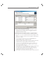
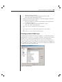
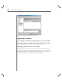
Accessing an Appliance
When you click the Appliances button, you will see a list of the appliances
currently defined in the local database. To access an appliance, you must first
log into it by typing in a username and password. Once you have logged into
an appliance, AVWorks will cache the username and password in memory for
the duration of the AVWorks session.
NOTE: You can clear the login credentials by selecting Tools - Clear Login Credentials.
18
AVWorks Installer/User Guide
Figure 3.4: Appliances View Tab Selected
To log into an appliance:
1.
Click the Appliances button in the AVWorks Explorer.
2.
Double-click on an appliance from the Unit Selector pane.
-orSelect an appliance, and then click the Manage appliance task button.
-orRight-click an appliance. A pop-up menu appears. Select Manage appliance.
-orClick an appliance in the Unit Selector pane and press Enter.
3.
A password prompt displays. Type in your username and password. The
default username is Admin (case sensitive) with no password.
NOTE: If you previously logged into the appliance during the same AVWorks session, the
password prompt will not appear.
4.
Click OK to access the appliance. This launches the AMP. For more
information about the AMP, see Chapter 4.
-orClick Cancel to exit without logging in.
Chapter 3: Basic Operations
19
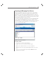
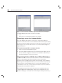
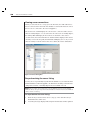
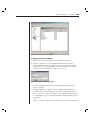
Accessing and Managing Your Devices
The Devices tab displays a list of devices (such as servers, routers and other
serially-managed devices) defined in the database. The Group Selector pane
appears if two or more device types are defined. Click All Devices or click on a
folder to view all devices of a particular type. When you select a server and click
the Connect Video task button, the Viewer launches. The Viewer allows you full
keyboard, monitor and mouse control over a server.
You can also scan through a customized list of servers by enabling individual
servers to appear in the Thumbnail Viewer. This view contains a series of
thumbnail frames, each containing a small, scaled, non-interactive version of a
server’s screen image. For more information, see Viewing multiple servers
using the Scan Mode in this chapter.
Figure 3.5: Devices View Tab Selected
To access a server:
1.
Click the Devices tab in the AVWorks Explorer.
2.
Double-click on the server from the Unit Selector pane.
-orSelect a server, and then click the Connect Video task button.
-orRight-click on the server. A pop-up menu appears. Select Connect Video.
-orClick a server in the Unit Selector pane and press Enter. The Viewer
launches in a new window.
20
AVWorks Installer/User Guide
To search for a server in the local database:
1.
Click the Devices tab and insert your cursor in the Search text box.
2.
Type the search information. This can be a device name or property such as
Type or Location.
3.
Click the Search button. The results appear in the Unit list.
4.
Review the results of your search.
-orClick the Clear Results button to display the entire list again.
To auto search by typing in the Unit list:
1.
Click the Devices tab, then click on any item in the Unit list.
2.
Begin typing the first few characters of a device name. The highlight will
move to the first device name beginning with those characters. To reset
the search so you can find another device, pause for a few seconds and
then type the first few characters of the next device.
Preempting the local user
If the server you are attempting to access is currently being viewed by the local
user, AVWorks allows you to preempt, or disconnect, the local user so that you
can access that server. You will see a notification display requesting that you
confirm the termination of the local user connection. The local user will
receive a notification message once you have confirmed.
NOTE: You cannot preempt the local user if he or she is in Broadcast mode. See the
AutoView 1000R/AV2000R Installer/User Guide for additional information.
To preempt the local user:
1.
Select a server to access and select the Connect Video task button.
2.
If the local user is already viewing this server, a message appears
informing you of this and requesting if you would like to terminate the
local user’s session. Click Yes to terminate the local user connection. The
Video Viewer launches.
-orClick No to allow the local user to retain the connection.
Interacting with the server being viewed
Once you have connected to a server, the server’s desktop appears in a
separate window called the Video Session Viewer. You will see both the local
and the server’s cursor. You may need to align these if they do not move
together or adjust the video if they seem to behave sporadically. See Aligning
the mouse or resetting the PS/2 connection in this chapter.
21
Chapter 3: Basic Operations
From this window, you will be able to access all the normal functions of this
server as if you were sitting in front of it. You may also perform Viewerspecific tasks such as sending special Macro commands to the server.
Viewer Window Features
A
C
D
E
B
Figure 3.6: Video Viewer Window
A. Menu bar: Access many of the features in the Viewer.
B. Accessed server desktop: Interact with your server through this window.
C. Full Screen Mode button: Expand the accessed server desktop to fill the entire screen.
D. Refresh Video button: Regenerate the digitized video image of the server desktop.
E. Align Local Cursor button: Re-establish proper tracking of the local cursor to the
remote server cursor.
Expanding and refreshing your Video Viewer
You can adjust your view using the three buttons at the top of the Video Viewer
window. The first button allows you to align the mouse cursors, the second is to
refreshes the video and the third expands the Video Viewer window to encompass
the entire screen. If you choose to expand the Video Viewer window, the menu bar
will disappear, but you will still see a small floating palette with these three
buttons, the Macros pulldown menu and the server name.
Figure 3.7: Full Screen Toolbar
To align the mouse cursors:
Click the Align Local Cursor button on the Viewer toolbar. The local cursor
will align with the cursor on the remote server.
22
AVWorks Installer/User Guide
To refresh the screen:
Click the Refresh Image button on the Viewer toolbar.
-orFrom the Viewer menu, select View - Refresh. The digitized video image will be
completely regenerated.
To enter full screen mode:
Click the Full Screen Mode button.
-orFrom the Viewer menu, select View - Full Screen. The desktop window will
disappear and only the accessed server desktop will be visible. The screen will
be resized up to a maximum of 1024 x 768. If the desktop has a higher
resolution, then a black background will surround the full screen image. The
floating toolbar will appear.
To exit full screen mode:
Click the Full Screen Mode button on the floating toolbar to exit full screen
mode and return to the desktop window.
Adjusting the Video Viewer window
You can adjust both the resolution and quality of the Video Viewer. You can also
expand your session to fit the entire screen or refresh the view at any time.
Adjusting the window size
The Video Viewer allows you to set up automatic or manual scaling of the
session image. When Auto Scale is selected, the desktop window remains fixed
and the server image is scaled to fit the window. When Manual Scale is selected,
a drop-down menu of supported image scaling resolutions is displayed.
To adjust the size of the Video Viewer window:
From the menu, select View - Auto Scale to allow the server image to be
scaled automatically.
-orFrom the menu, select View - Manual Scale, then choose the dimension to
scale the window.
Chapter 3: Basic Operations
23
Figure 3.8: Viewer Manual Scale
Adjusting the video quality
The Video Viewer offers both automatic and manual video adjustment
capability. Generally, the Automatic Video Adjustment will optimize the video
for the best possible view. However, you may fine tune the video with the aid
of Avocent Technical Support. See Appendix E: Troubleshooting. Video
adjustment is a global setting and applies to each target device you access.
Adjusting mouse settings
The Video Viewer allows you to select among five different mouse cursor
options, set up mouse scaling and resynchronize your mouse should it no
longer track properly. Mouse settings are target device-specific and can be set
differently for each. These settings are placed into the local client database and
applied each time you launch a session to a specific device.
24
AVWorks Installer/User Guide
Figure 3.9: Viewer Mouse Session Options Dialog Box
Setting mouse scaling
You can choose among three preconfigured mouse scaling options or set your
own custom scaling. The preconfigured settings are: Default (1:1), High (2:1)
or Low (1:2). In a 1:1 scaling ratio, every mouse movement on the desktop
window will send an equivalent mouse movement to the server. In a 2:1
scaling, the same mouse movement will send a 2X mouse movement. In a 1:2
scaling, the value will be 1/2X.
To set custom mouse scaling:
1.
Select Tools - Session Options. The Session Options dialog box appears.
2.
Click the Mouse tab.
3.
Click the Custom radio button. The X and Y fields become enabled.
4.
Type a mouse scaling value in the X and Y fields. For every mouse input,
the mouse movements are multiplied by the respective X and Y scaling
factors. Valid input ranges are 0.25 to 3.00.
Aligning the mouse or resetting the PS/2 connection
If you find that your mouse or keyboard no longer responds properly, you can align
the mouse to re-establish proper tracking or reset the PS/2 connection. Resetting
this connection causes the appliance to simulate a mouse and keyboard reconnect
at the server as if you had disconnected and then reconnected them. Alignment
causes the local cursor to be aligned with the cursor on the remote server.
NOTE: If the server does not support the ability to disconnect and reconnect the mouse (almost
all newer PCs do), then the mouse will become disabled and the server will have to be rebooted.
Chapter 3: Basic Operations
25
To realign the mouse:
Click the Align Local Cursor button on the Viewer toolbar.
To reset the PS/2 connection:
1.
Select Tools - Session Options in the Viewer. The Session Options dialog
box appears.
2.
Click the Mouse tab.
3.
Click the Reset PS/2 button. A dialog box appears prompting you to confirm.
4.
Click the Reset PS/2 Connection at the Device checkbox and click OK.
Viewing multiple servers using the Scan Mode
The Video Viewer allows you to simultaneously view multiple servers through
the Thumbnail Viewer of the Scan Mode. This view contains a series of
thumbnail frames, each containing a small, scaled, non-interactive version of a
server’s screen image. The server name displays below each thumbnail as
well as the status indicator.
Scanning your servers
Through the Thumbnail Viewer, you can set up a scan sequence of up to 16
servers to monitor your servers. The scan mode moves from one thumbnail
image to the next, logging into a server and displaying an updated server
image for a user-specified length of time (View Time Per Server), before
logging out of that server and moving on to the next thumbnail image. You can
also specify a scan delay between thumbnails (Time Between Servers). During
the delay, you will see the last thumbnail image for all servers in the scan
sequence, though you won’t be logged into any servers.
When you first launch the Thumbnail Viewer, each frame will be filled with a
white background until a server image is displayed. An indicator light at the
bottom of each frame displays the status of the server. The default thumbnail
size is based on the number of servers in the scan list.
Scan mode is a lower priority than an active connection. If you have an
interactive session with a server, that server will be skipped in the scan
sequence and the scan mode will proceed to the next server. No login error
messages will appear. Once the interactive session is closed, then the
thumbnail will be included in the scan sequence again. If another user has an
active connection to a server, you will still see that thumbnail in your scan list.
To access the Scan Mode:
1.
Select the Servers, Sites or Folders tab.
26
AVWorks Installer/User Guide
2.
Select two or more servers in the unit selector pane pressing the Shift or
Control key. The Scan Mode task button appears.
3.
Click the Scan Mode task button. The Thumbnail Viewer window appears.
Figure 3.10: Video Viewer - Thumbnail View
Thumbnail View Status Indicators
Symbol
Description
The green LED indicates that a server is currently being scanned.
The red X indicates that the last scan of the server was not successful. The
scan may have failed due to a credential or path failure (the server path on the
AutoView 1000R/2000R was not available), or because of some other reason.
The tool tip for the LED indicates the reason for failure.
To set scan preferences:
1.
From the Thumbnail View, select Options - Preferences. The Preferences dialog
box appears.
2.
Enter the time each thumbnail will be active during the scan (5 to 60
seconds) in the View Time Per Server box.
3.
Enter the length of time the scan stops between each server (5 to 600
seconds) in the Time Between Servers box.
4.
Click OK.
Chapter 3: Basic Operations
27
Navigating the Thumbnail Viewer
When you highlight an individual thumbnail frame and select the Thumbnail
menu, you can launch an interactive session to that server, add that server to
the scan sequence or set the login credentials for that server.
The Options menu allows you to access scanning preferences as well as pause
the scan and set the thumbnail size for all servers.
To launch a server Video session:
Select a server thumbnail. From the Thumbnail Viewer, select Thumbnail {servername] - View Interactive Session.
-orRight-click over a server thumbnail and select View Interactive Session. That
server’s video will be launched in an interactive Video Viewer window.
To add an individual server to the scan sequence:
Select a server thumbnail. From the Thumbnail Viewer, select Thumbnail [server name] - Enable.
-orRight-click over a server thumbnail and select Enable. That server will include
the server thumbnail in the scan sequence.
NOTE: If a server is being accessed by a user, the Enable Scan menu will be disabled for that
server thumbnail.
To set server credentials:
1.
Select a server Thumbnail. From the Thumbnail View, select Thumbnail [server name] - Credentials.
-orRight-click over a server thumbnail and select Credentials. The Login
dialog box appears.
2.
Enter a Username and Password for the selected server.
To pause or restart a scan sequence:
From the Thumbnail Viewer, select Options - Pause Scan. The scan sequence will
pause at the current thumbnail if the Thumbnail Viewer has a scan in progress or
will restart the scan if currently paused.
To change the thumbnail size:
From the Thumbnail Viewer, select Options - Thumbnail Size. Select the desired
thumbnail size from the cascade menu.
28
AVWorks Installer/User Guide
Using macros to send keystrokes to a device
The Macros menu in the Video Viewer provides you with an easy way to send
multiple keystrokes to a server or to send keystrokes that you cannot generate
without affecting your local system, such as Control-Alt-Delete. The Viewer
provides a list of default keystroke selections; however, you may set up your
own macros, as well as change the set that displays by default, by selecting the
Configure option at the bottom of the Macros pulldown menu.
Figure 3.11: Viewer Macro Menu Expanded
Sending keystrokes to a device
Select the Macros menu in the Viewer and choose the macro to send to the
server. Figure 3.11 shows the default macros that ship with AVWorks. If you do
not see the keystroke you need, select Configure to access the Macros dialog
box. Here you can create, modify, delete and group macros.
Macro Groups settings are specific to each target device and, therefore, can be
set differently for each server. These settings are placed into the local client
database and applied each time you launch a session to a specific device.
To change the default Macro group:
1.
Select Tools - Session Options in the Viewer. The Session Options dialog
box appears.
2.
Click the Macros tab.
Chapter 3: Basic Operations
29
Figure 3.12: Viewer Session Options Dialog Box - Macro Tab
3.
Select a macro group from the pulldown list to appear in the Macro menu
and click OK.
Creating new macros
You can create custom macro keystrokes as well as modify and delete existing
macros through the Macros dialog box.
To create a new macro:
1.
Select Macros - Configure from the Viewer. The Macros dialog box appears.
30
AVWorks Installer/User Guide
Figure 3.13: Viewer Macro Dialog Box
2.
Click Create. The Create/Edit Macros dialog box appears.
Figure 3.14: Viewer Create/Edit Macro Dialog Box
3.
Type the name of the macro in the Macro Name field.
Chapter 3: Basic Operations
4.
Select the desired category and keystrokes from the list of Available
Keystrokes and click Add.
-orType the keystrokes to send in the Keystrokes field.
a.
5.
31
To enter a keystroke such as Enter, Home or Insert, surround each
individual keystroke with a less than (<) and greater than (>) symbol.
-orTo enter a letter or number, type the letter or number without any
additional symbols.
-orFor auxiliary keystrokes such as Control, Shift or Alt, where a press,
hold and release are required to complete a command, type the initial press keystroke (such as <Ctrl-Press>), then the keystroke, letter
or number of the command, followed by the closing release (such as
<Ctrl-Release>). See the example in Figure 3.14.
Click OK to accept the macro and return to the Macros dialog box.
-orClick Reset to erase all the keystrokes entered in the Keystrokes field.
Grouping macros
The Macro Groups dialog box allows you to arrange macros into logical
groups. Macro groups for Windows and Sun are already predefined; you can
alter either of these two groups or create an entirely new group. You can also
rename and delete groups that have been previously created.
To create a macro group:
1.
Select Macros - Configure from the Viewer. The Macros dialog box appears.
2.
Click Group. The Macro Groups dialog box appears. The Macros Available
box contains macros that are not currently in use by this group.
32
AVWorks Installer/User Guide
Figure 3.15: Viewer Macro Groups Dialog Box
3.
Click Create. A dialog box appears prompting you to name the new macro group.
4.
Type in a name. Click OK to save the name and return to the Macro
Groups dialog box. A tab with the new name appears.
To add macros to an existing group:
1.
Select Macros - Configure from the Viewer. The Macros dialog box appears.
2.
Click Group. The Macro Groups dialog box appears.
3.
Click the macro group tab to alter. Windows and Sun are the default tabs.
If you have created a new group, you will see a tab for this group as well.
4.
Click on the macro to add from the Macros Available pane on the left side
of the dialog box. Click the Add button. The macro appears in the Macros
in Group box. Use the Move Up and Move Down buttons to move the
macro up or down in relation to the other macros.
5.
Repeat step 4 until all the macros to be grouped appear in the Macros In
Group box.
6.
Click OK to accept the macro group and return to the Macros dialog box.
-orClick Cancel to leave this dialog box without saving changes.
Chapter 3: Basic Operations
33
To remove macros from an existing group:
1.
Select Macros - Configure from the Viewer. The Macros dialog box appears.
2.
Click Group. The Macro Groups dialog box appears.
3.
Click the macro group tab to alter. Windows and Sun are the default tabs.
If you have created a new group, you will see a tab for this group as well.
4.
Click on the macro to remove from the Macros in Group pane on the right
side of the dialog box. Click the Remove button. The macro appears in the
Macros Available box.
5.
Repeat step 4 until all the macros to be removed appear in the Macros
Available box.
6.
Click OK to accept the macro group and return to the Macros dialog box.
-orClick Cancel to leave this dialog box without saving changes.
Changing AVWorks Device Properties
You can alter device properties from the AVWorks Explorer Properties dialog
box including General, Network, Information and Connections. The General
tab allows you to change the device name, device type and the icon that will be
used to display the server in AVWorks. You may also assign the server to a site,
location or folder. The Network tab lets you set a browser URL for that server if you
want to view it in a browser window instead of through a session Viewer. The
Information tab allows you to enter information about the server including a server
description, contact information and any comments you would like to add. Lastly,
the Connections tab displays the connection that will be used for a specific server.
NOTE: You can also change the properties of your appliance. For more information, see Chapter 4.
To change device properties:
1.
Select an individual server in the Unit Selector list.
2.
Select View - Properties from the AVWorks Explorer menu.
-orClick the Properties task button. The Properties dialog box appears.
34
AVWorks Installer/User Guide
Figure 3.16: Server General Properties Tab
3.
Type in the new name of the server. A warning will display if you enter a
duplicate name.
4.
(Optional) Select the device type. If the selection is not in the pulldown,
type the name of the new server type in the text field. Once entered, the
option becomes available in the pulldown for future assignment.
5.
(Optional) Select the icon to display for the unit.
6.
(Optional) Assign a server to a site, department or location. (These
categories are customizable. See Modifying custom field names in this
chapter.) If an option is not in the pulldown, type the name of the new
assignment in the text field. Once entered, the option becomes available in
the pulldown for future assignment.
7.
(Optional) Click the Network tab and type in the URL to use when
establishing a browser connection to the server. If the field contains a
value, then the Browser button appears in the task bar allowing you to
launch the browser to that specified URL.
Chapter 3: Basic Operations
35
Figure 3.17: Server Network Properties Tab
8.
(Optional) Click the Information tab and type in a description of the unit.
There are no rules for the type of information that you may enter here.
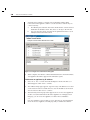
Figure 3.18: Server Information Tab
9.
(Optional) Click the Connections tab to view the physical connection path that
will be used to access this device. This feature is useful for troubleshooting.
Figure 3.19 shows a connection to a server. Figure 3.20 shows a server
connected to Channel 1 of a legacy switch.
36
AVWorks Installer/User Guide
Figure 3.19: Server Connection Example Figure 3.20: Switch Connection Example
10. When finished, click OK to save the new settings.
-orClick Cancel to exit without saving the new settings.
Accessing a server via a browser window
You can configure your system to open a server connection in a browser
window. You must first select a server and define a URL in the Properties dialog
box as previously described. Then, when you select the server, the Browse task
button appears. You can select the browser to use in the AVWorks Explorer’s
Options dialog box.
To launch the server URL in a browser window:
1.
Select a server in the Unit Selector pane.
2.
If you have defined a URL for this server in the Properties dialog box, the
Browse task button appears. Click the Browse task button. The URL you
identified will launch in a browser window.
Organizing Units with the Local Client Database
The local client database provides persistent storage for unit names,
properties, network addresses and custom session settings. Device attributes
such as type, site and department allow you to create and store logical groups
for your devices. Custom folders allow you to group units within the local
client database. View tabs, sort bars and search functions use these attributes
to find specific units within the database.
Site organization is based on where your servers are located and refers to the
column headings Site and Department, which can be customized to suit your
needs. See Modifying custom field names in this chapter. Folders provide a way to
Chapter 3: Basic Operations
37
create a customized organizational system for individual servers. For example,
you might want to create a folder for critical servers or for remote servers.
You may change the order and sorting of the Unit Selector list by clicking the
sort bar above the column. An upward-pointing arrow in a column header
indicates that the list is sorted by that field name in ascending order. A
downward-pointing arrow indicates the list is sorted by that field name in
descending order.
The sort bar properties are customizable. Figures 3.21 and 3.22 show examples
of how you might use the default field name values. You may change them to fit
your own organization. Figure 3.23 features customized field names.
Figure 3.21: Sites View Tab Selected
38
AVWorks Installer/User Guide
Figure 3.22: Folders View Tab Selected
Modifying custom field names
Custom field names allow you to change the Site, Department and Location
column heading names that appear in the Group and Unit Selector panes. This
allows you to group appliances and servers in ways that are meaningful to
you. The Department field is a subset of Site. If you customize these field
names, you should keep this hierarchy in mind.
Figure 3.23: Example of Modified Custom Fields
To modify a custom field label:
1.
Select Tools - Options from the AVWorks Explorer menu. The Options
dialog box appears.
Chapter 3: Basic Operations
39
Figure 3.24: Options Dialog Box - Custom Field Labels
2.
Select a field label to modify and click the Modify button. The Modify
Custom Field Label dialog box appears.
3.
Type the singular and plural versions of the field label. The length can be
from 1 to 32 characters. A blank value is not allowed. Spaces are permitted
in the middle but leading and trailing spaces are not allowed.
4.
Click OK to save the new field label.
-orClick Cancel to exit without saving changes.
Creating new sites, departments, locations or folders
You can organize units within your local database into sites, departments
locations or folders by assigning a unit to that structure. Sites, departments and
locations all appear under the Sites tab. These default headings can be
changed. See Modifying custom field names in this chapter. Folders appear
under the Folders tab and provide unlimited organizational options. You may
name and structure folders in any way you choose.
To create a new site, department or location:
1.
Select View - Properties from the AVWorks Explorer menu.
-orClick the Properties task button. The Properties dialog box appears.
2.
Click the General tab and select the pulldown menu for Site, Department
40
AVWorks Installer/User Guide
or Location. If a name is not in the pulldown menu, type the name you
want in the text field. The name can be from 1 to 32 characters long. Names
are not case sensitive and can consist of any combination of characters
entered from the keyboard. Spaces are permitted in the middle but leading
and trailing spaces are not allowed. Duplicate names are not allowed.
3.
Click OK. The new site, department or location appears in the Group
Selector pane.
To create a new folder:
1.
Select the Folders View tab.
2.
Click on the top-level Folders node and select File - New - Folder.
-orRight-click on the Folders node and select New Folder. The New Folder
dialog box appears.
-or
Click on an existing folder and select File - New - Folder to create a nested folder.
3.
Type in a name for the folder from 1 to 32 characters long. Folder names
are not case sensitive and can consist of any combination of characters
entered from the keyboard. Spaces are permitted in the middle but leading
and trailing spaces are not allowed. Duplicate folder names are not
allowed at the same level but are allowed across different levels.
4.
Click OK. The new folder appears in the Group Selector pane.
Assigning a unit to a site, location or folder
Once you have created a new site, location or folder, you can assign an
appliance or server to that organization. The Assign menu item is only enabled
when a single appliance or server is selected in the Unit Selector pane. These
custom assignment targets are defined in the General Properties dialog box.
To assign a unit to a site, location or folder:
1.
Select a unit in the Unit Selector pane.
2.
Select Edit - Assign from the AVWorks Explorer menu.
-orClick the Assign To task button.
-or
Right-click on a unit and select Assign To. The Assign To dialog box appears.
Chapter 3: Basic Operations
41
Figure 3.25: Assign To Dialog Box
3.
Select the site, location or folder category from the pulldown menu.
4.
Select the target from the list of available targets to which the unit can be
assigned within the chosen category. This could be empty if no site,
location or folder has been defined in the local database.
5.
Click OK to save the assignment.
-orClick Cancel to exit without saving changes.
To drag and drop a unit into a site, location or folder:
Click and hold on a unit in the Unit list. Drag the item on top of a folder icon
(node) in the tree view of the Group Selector pane. Release the mouse button.
The item now appears in the Unit list when you click that node.
NOTE: A unit cannot be moved to All Departments, All Units or the root Sites node. Units can
only be moved one at a time.
Deleting and Renaming
The delete function works based on what is currently selected in the Group and
Unit Selector panes. When you select and delete a unit in the Unit list, it is
removed from the local database. This will not affect the configurations in OSCAR.
When you select and delete an item in the tree view of the Group Selector pane,
you will delete Server Types, Sites, Departments or Folders; however, none of the
actions result in units being deleted from the local database.
The rename function is also dependent on what is currently selected. You can
select and rename an appliance or a server from the Unit list. You can select
and rename server types, sites, departments and folder names in the tree view
of the Group Selector pane.
NOTE: If you delete or rename a server through AVWorks, the OSCAR server list at the local
analog workstation becomes out of date. Resynching will not download server names into OSCAR.
Devices should be deleted or renamed from OSCAR and then resynchronized in AVWorks.
42
AVWorks Installer/User Guide
To delete an appliance or server:
1.
Select the unit(s) to delete from the Unit Selector pane.
2.
Select Edit - Delete.
-orPress the Delete key on your keyboard. A dialog box appears confirming the
number of units to be deleted. If you are deleting an appliance, the dialog box
includes a Delete Associated Devices checkbox. Enable/disable the checkbox
as desired. If you do not delete the associated devices, they will still appear in
the devices list, however, you will not be able to connect video to them.
3.
Click Yes to confirm the deletion. Additional message prompts may appear
depending on your configuration. Respond as appropriate. The appliance
or server is deleted.
-orClick No to cancel.
To delete a device type, site, department or folder:
1.
Select the device type, site, department or folder to delete from the Group
Selector pane.
2.
Select Edit - Delete.
-orPress the Delete key on your keyboard. A dialog box appears confirming
the number of units that will be affected by this deletion.
3.
Click Yes to confirm the deletion. Additional message prompts may
appear depending on your configuration. Respond as appropriate. The
element is deleted.
-orClick No to cancel.
To rename a device type, site, department or folder:
1.
In the Group Selector pane, click on the device type, site, department or
folder to rename.
2.
Select Edit - Rename. The Rename dialog box appears.
3.
Type in a name from 1 to 32 characters long. Names can consist of any
combination of characters entered from the keyboard. Spaces are
permitted in the middle but leading and trailing spaces are not allowed.
Duplicate names are not allowed, including the same name with different
cases, with two exceptions: department names can be duplicated across
different sites and folder names can be duplicated across different levels.
4.
Click OK to save the new name.
-orClick Cancel to exit without saving changes.
Chapter 3: Basic Operations
43
Customizing the AVWorks Explorer Window
The AVWorks Explorer window can be resized at any time. Each time you
launch the application, the AVWorks Explorer window opens to its default size
and location.
A split-pane divider that runs from top to bottom separates the Group Selector
pane and the Unit Selector pane. You can move the divider left and right to
change the viewing area of the Group Selector pane and the Unit Selector
pane. Each time AVWorks Explorer is started, the divider will appear in its
default location. See Appendix B for divider pane and tree view control mouse
and keyboard shortcuts.
Modifying the selected view on startup
When Default is checked under the selected view on the startup option, the
AVWorks Explorer will determine which view to display. If you have one or
more servers defined, the Devices display will appear by default. If you do not,
the Appliances display will appear.
When Default is unchecked, the AVWorks Explorer will display the view
selected in the pulldown menu shown below the checkbox. The pulldown
menu contains the following values: Appliances, Devices, Sites and Folders.
The pulldown menu is only enabled when the checkbox is unchecked.
To modify the selected view on startup:
1.
Select Tools - Options from the AVWorks Explorer menu. The Options
dialog box appears.
2.
Select Appliances, Devices, Sites or Folders from the pulldown menu.
3.
Click OK to save the new startup view.
-orClick Cancel to exit without saving changes.
Changing the default browser
You can specify which browser launches when viewing a server URL in a
browser window. You have the option of using the default browser for your
system, or you can select a specific browser to launch for that server.
To change the default browser:
1.
Select Tools - Options from AVWorks Explorer. The Options dialog box appears.
2.
Deselect the Launch Default Browser checkbox. The Browse button is enabled.
3.
Click the Browse button and navigate to the browser.
44
AVWorks Installer/User Guide
4.
Click OK to save the new browser selection.
-orClick Cancel to exit without saving changes.
Managing Your Local Databases
Each workstation running AVWorks contains a local database that records the
information that you enter about your units. If you have multiple workstations,
you may configure one station and then save a copy of this database and load it
into the other stations to avoid unnecessarily reconfiguring each station. You
may also export the database for use in another application.
Saving a database
AVWorks allows you to save a copy of the local database for later use. The
saved database can then be loaded back to the same computer where it was
created, or it can be loaded onto another AVWorks client. The saved database
is compressed into a single Zip file.
While the database is being saved, no other activity is allowed. All other
windows including Video Session windows and Appliance Management Panel
windows must be closed. If other windows are open, a message will appear
prompting you to either continue and close all open windows or quit and
cancel the database save process.
To save a database:
1.
Select File - Database - Save. The Database Save dialog box appears.
Figure 3.26: Database Save Dialog Box
2.
Type in a file name and choose a location to save the file.
3.
Click Save. A progress bar appears during the save. When finished, a
message appears indicating that the save was successful and you are
returned to the main window.
Chapter 3: Basic Operations
45
Exporting a database
This function allows you to export fields from the local database to an ASCII
Comma Separated Value file (CSV) or Tab Separated Value file (TSV). The
following database fields will be exported.
Exported Database Fields
AutoView 1000R/2000R Flag
Type
Name
Address
Custom Field 1
Custom Field 2
Custom Field 3
Description
Contact Name
Contact Phone #
Comments
Browser URL
NOTE: The Address field only applies to appliances and the Browser URL field only applies to
servers. In the exported file, the Address field data will be empty for servers and the Browser
URL field data will be empty for appliances.
The first line of the exported file contains the column names for the field data.
Each additional line contains the field data for an appliance or server. The file
will contain one line for each appliance and server defined in the local database.
To export a database:
1.
Select File - Database - Export from the AVWorks Explorer menu. The
Database Export dialog box appears.
2.
Select a database to export.
3.
Type in a file name and browse to the location to save the exported file.
4.
Click Export. A progress bar appears during the export. When finished, a
message appears indicating that the export was successful and you are
returned to the main window.
Loading a database
This function allows you to load a database that was previously saved. While the
database is being loaded, no other activity is allowed. All other windows including
Video Session windows and Appliance Management Panel windows must be
closed. If other windows are open, a message appears prompting you to either
continue and close all open windows or quit and cancel the database save process.
46
AVWorks Installer/User Guide
To load a database:
1.
Select File - Database - Load from the AVWorks Explorer menu. The
Database Load dialog box appears.
2.
Browse to select a database to load.
3.
Click Load. A progress bar appears during the load. When finished, a
message appears indicating that the load was successful and you are
returned to the main window.
4
Managing Your Appliance
Contents
Viewing and Configuring Appliance Parameters . . . . .
Upgrading Firmware . . . . . . . . . . . . . . . . . . . . . . . . . . .
Managing User Sessions . . . . . . . . . . . . . . . . . . . . . . . . .
Rebooting Your Appliance . . . . . . . . . . . . . . . . . . . . . . .
Managing Appliance Configuration Databases . . . . . .
Managing User Databases . . . . . . . . . . . . . . . . . . . . . . .
Changing Appliance Properties . . . . . . . . . . . . . . . . . . .
Adding and Deleting Product Licenses . . . . . . . . . . . . .
50
58
61
61
62
62
63
66
Chapter 4: Managing Your Appliance
49
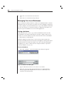
Chapter 4: Managing Your Appliance
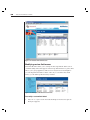
Once you have installed a new appliance, you have the ability to view and
configure unit parameters, view and control currently active video sessions
and execute a variety of control functions such as rebooting and upgrading
your appliance. This is accomplished through the Appliance Management
Panel (AMP). The AMP has three tabbed panels: Settings, Status and Tools.
Figure 4.1: Appliance Management Panel Dialog Box
To access the AMP:
1.
Click the Appliances button in the AVWorks Explorer.
2.
Double-click on an appliance from the Unit Selector pane.
-orSelect an appliance from the Unit Selector pane, then click the Manage
appliance task button.
-orRight-click on an appliance in the Unit Selector pane. A pop-up menu
appears. Select Manage appliance.
-orClick an appliance in the Unit Selector pane and press Enter.
3.
A password prompt appears. Type in your username and password and
click OK. The default username is Admin with no password.
NOTE: AVWorks caches your user credentials until the application is closed. You do not need
to re-enter your credentials for each session.
4.
The Appliance Management Panel dialog box appears.
50
AVWorks Installer/User Guide
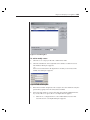
Viewing and Configuring Appliance Parameters
The Settings tab allows you to display an expandable list of categories covering
a wide range of parameters for your appliance. When a category is selected
from the list, the parameters associated with the category will first be read
from the unit, the local database or both. You will then be able to modify those
parameters and send the changes securely back to the appliance.
Changing global network and session parameters
The Global category allows you to view the product type, part and serial number
and language setting for the appliance. If you select the Network sub-category,
you will be able to change the network settings including the IP address, subnet
mask, gateway, LAN speed and BootP setting. If you select the Sessions subcategory, you can enable the session time-out to allow the appliance to close an
inactive video session after a specified number of minutes.
Setting up user accounts
When you select the Users category for the first time, the AMP will retrieve and
display a list of usernames and current access levels from the appliance. You
can add, modify or delete users in this listing. You can assign three access
levels: User, User Administrator and Appliance Administrator. The User
Access level allows you to assign individual server access rights to a user.
Users can become locked out by the Security Lock-out feature if they try to
enter an invalid password five consecutive times. You can configure Security
Lock-out settings as well as unlock any user through the Users category.
User Access Level Rights
Operations
Appliance
Administrator
User
Administrator
User
Preemption
All
Equal and lesser
Equal and Lesser
Configure network & global
settings (security mode,
time-out, SNMP)
Yes
No
No
Reboot
Yes
No
No
FLASH upgrade
Yes
No
No
Administer user accounts
Yes
Yes
No
Configure port settings
Yes
Yes
No
Monitor server status
Yes
Yes
No
Break
Yes
Yes
Yes
Target Device Access
Yes
Yes
Assigned by Admin
Chapter 4: Managing Your Appliance
51
Figure 4.2: Users Dialog Box
To add or modify a user:
1.
Click the Users category in the left column in the AMP.
2.
Click the Add button on the right side of the window to add a new user.
The Add User dialog box appears.
-orSelect a user and click the Modify button to modify a current user. The
Modify User dialog box appears.
Figure 4.3: Add User Dialog Box
3.
Enter the username and password to assign to the user and then verify the
password by typing it into the Verify Password field.
4.
Select the appropriate access level for this user from the pulldown menu.
If you select the User option, the Access Rights button appears.
a.
Click the Access Rights button to select individual servers for that
user. The User Access Rights dialog box appears.
52
AVWorks Installer/User Guide
Figure 4.4: User Access Rights Dialog Box
b.
c.
d.
5.
Select a server in the left column for which this user should have
access rights. Select the Add button.
Select a server in the right column from which to remove a user’s
access rights. Click the Remove button.
Repeat steps a and b until the right column represents the appropriate server access for this user, and then click OK.
Click OK to save the settings and return to the main AMP window.
To delete a user:
1.
Click the Users category in the left column in the AMP and then select the
user(s) to delete.
2.
Click the Delete button on the right side of the AMP Users window. A
confirmation window appears.
3.
Click Yes to confirm the deletion.
-orClick No to exit the window without deleting the user.
Locking and unlocking user accounts
If a user enters an invalid password five consecutive times, the Security LockOut feature will temporarily disable that account. If a user attempts to log in
again, the software client application displays an appropriate error message.
All accounts (user, user admin and appliance admin) are subject to this lockout policy.
An appliance administrator can specify the number of hours (1 to 99) that
accounts will remain locked. When Enable Lock-outs is unchecked, the
security lock-out feature will be disabled and no users will be locked out.
If an account becomes locked, it will remain locked until the Duration time
has elapsed, the appliance is power-cycled or an administrator unlocks the
account via the AMP. A user administrator may unlock only user accounts,
whereas an appliance administrator may unlock any type of account.
Chapter 4: Managing Your Appliance
53
To unlock an account:
1.
Click the Users category in the AMP.
2.
Select the user to unlock.
3.
Click the Unlock button. The lock icon next to the user name will disappear.
4.
Click OK or Apply. The user will be able to attempt to log in again.
-orClick Cancel to exit without saving.
To specify the length of time a user account remains locked:
1.
Click the Users category in the MP.
2.
Click the Enable Lock-outs checkbox.
3.
Enter the number of hours that a user will be locked out (1 to 99).
To disable the Security Lockout feature:
1.
Click the Users category in the MP.
2.
Uncheck the Enable Lock-outs checkbox. The Duration field is disabled.
NOTE: Disabling Security Lockout will have no affect on users that are already locked out.
Viewing the AVRIQ adaptors
The AVRIQs category lets you view the AVRIQ adaptors in your system, their port
and EID numbers as well as the computer type and keyboard language. You can
also view the AVRIQ status. A green circle indicates that the AVRIQ is online. A
yellow circle means the AVRIQ is being upgraded and a red X indicates that the
AVRIQ is offline.
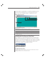
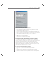
Enabling and configuring SNMP
SNMP (Simple Network Management Protocol) is a protocol used to communicate
management information between network management applications and
appliances. Other SNMP managers (such as Tivoli and HP OpenView) can
communicate with your appliance by accessing MIB-II (Management Information
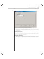
Base) and the public portion of the enterprise MIB. MIB-II is a standard MIB that
many SNMP servers support. When you select the SNMP category for the first
time, the AMP will retrieve the SNMP parameters from the unit.
In this dialog box, you can enter system information and community strings.
You may also designate which stations can manage the appliance as well as
receive SNMP traps from the switch. For more information on traps, see
Enabling individual SNMP traps in this chapter. If you check Enable SNMP, the
54
AVWorks Installer/User Guide
unit will respond to SNMP requests over UDP (User Datagram Protocol) port
161. Port 161 is the standard UDP port used to send and receive SNMP messages.
If you enter one or more allowable managers, only those IP addresses will be
able to manage the appliance via SNMP. If you do not enter any allowable
managers, then the appliance can be managed via SNMP from any IP address.
NOTE: The AMP uses SNMP within a secure tunnel to manage appliances. For this reason,
UDP Port 161 need not be exposed on firewalls. You will need to expose UDP Port 161 to
monitor Avocent appliances via third-party SNMP-based management software.
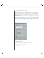
Figure 4.5: SNMP Configuration Dialog Box
To configure general SNMP settings:
1.
Click the SNMP category in the left column in the AMP.
2.
Click the Enable SNMP checkbox to allow the appliance to respond to
SNMP requests over UDP port 161.
3.
Enter the system’s fully qualified domain name in the Name field, as well
as a description and node contact person in the System section.
4.
Enter the Read, Write and Trap community names. These specify the
community strings that must be used in SNMP actions. The Read and
Write strings only apply to SNMP over UPD port 161 and act as passwords
that protect access to the appliance. The values can be up to 64 characters
in length.
5.
Add up to four SNMP management entities to monitor this appliance or leave
this blank to allow any station to monitor the appliance.
a.
Click the Add button to define an allowable manager. The Allowable
Chapter 4: Managing Your Appliance
b.
c.
6.
Manager dialog box appears.
Type in the IP address of the management station to add.
Click OK to add a management station.
Add up to four SNMP trap destinations to which this appliance will send
traps in the Trap Destination field.
a.
b.
c.
7.
55
Click the Add button to define a trap destination. The Trap Destination dialog box appears.
Type in the IP address of the trap destination to add.
Click OK to add a trap destination.
Click OK to save the settings and close the window.
-orClick Apply to save the settings and remain in the open window.
-orClick Cancel to exit the window without saving.
Enabling individual SNMP traps
An SNMP trap is a notification sent by the appliance to a management station
indicating that an event has occurred in the appliance that may require further
attention. You can specify what SNMP traps are sent to the management
stations by simply clicking the appropriate checkboxes in the list. When you
select the Traps category for the first time, the AMP will retrieve and display a
list of SNMP traps from the appliance. You may select Enable All or Disable All
to easily select or deselect the entire list.
Figure 4.6: Traps Dialog Box
56
AVWorks Installer/User Guide
Viewing server connections
When you select the Devices category for the first time, the AMP will retrieve
the servers that exist in the AVWorks database as well as information on how
the servers are connected to the selected appliance.
The Connection column displays the current server connection. This can be to
either an AVRIQ adaptor or a cascade switch. If connected to an AVRIQ adaptor,
the AVRIQ’s EID will display in the Connection column. If connected to a
cascade switch, the switch and all of its channels will be displayed. If no unit is
currently connected to the path, then this field will display as None. If you click
either an AVRIQ or switch in the Connection column, the Viewer will launch.
Figure 4.7: Devices Dialog Box
Resynchronizing the server listing
You may choose to periodically resynchronize the database on your AVWorks client
with the database stored in the appliance. Do this if the local analog workstation has
changed server names or if AVRIQ adaptors have been added or moved.
NOTE: This procedure only resynchronizes your own AVWorks client. If you have multiple
AVWorks clients, save your resynchronized local database and load it into the other AVWorks
client to ensure consistency.
To resynchronize the server listing:
1.
Click the Resync button in the Server category of the AMP. The Resync
Wizard launches. Click Next.
2.
A warning message displays indicating that the database will be updated
Chapter 4: Managing Your Appliance
57
to match the current configuration in the appliance. Your current local
database names will be overridden with the appliance names. Click Next.
3.
A polling appliance message box appears with a progress bar indicating
that the appliance information is being retrieved.
4.
If no changes were detected in the appliance, a completion dialog box
appears with this information.
-orIf server changes were detected, then the Detected Changes dialog box
will be displayed. Click Next to update the database.
a.
5.
If a cascade switch was detected, the Enter Cascade Switch Information dialog box appears. Select the type of switch connected to
the appliance from the pulldown menu. If the type you are looking
for is not available, you can add it via the Add button. For more
information, see Configuring cascade switch connections in this
chapter. Click Next.
The completion dialog box appears. Click Finish to exit.
Configuring cascade switches connections
The Cascade Switches category lets you view the cascade switches in your system
and the AVRIQ adaptor EID numbers as well as the type of switch and the port to
which it is connected.
To configure a cascade switch connection:
1.
Click the Cascade Switches category in the left column in the AMP.
2.
Click the pulldown list next to the switch and select the switch type to assign.
-orIf the switch type isn’t in the pulldown list, add a switch to the Existing
Cascade Switches list by clicking the Add button.
a.
b.
The Add Cascade Switch dialog box appears. Type the name of the
switch and select the switch type from the list.
Click OK to add the switch. The switch should now be in the Existing
Switches list and in the Switch pulldown list.
3.
Repeat step 2 for each switch that you wish to configure.
4.
When finished, click OK to save the new settings.
-orClick Cancel to exit without saving.
58
AVWorks Installer/User Guide
Figure 4.8: Configure Cascade Switches Dialog Box
Upgrading Firmware
You can upgrade the firmware for either the appliance or the AVRIQ adaptors.
The AVRIQ adaptors can be upgraded individually or simultaneously. When
an upgrade is initiated, you will see a message indicating the current status. As
long as an upgrade is in progress, you cannot initiate another.
Viewing appliance Version information
When you select the Versions category for the first time, the AMP will retrieve
the firmware versions from the appliance. The Hardware sub-category displays
the version information for the unit itself. The AVRIQs sub-category allows you
to view and upgrade all of the AVRIQ adaptors in the system.
Chapter 4: Managing Your Appliance
59
Figure 4.9: Firmware Version Dialog Box
To upgrade appliance firmware:
1.
Click the Tools tab in the AMP. The Tools dialog box appears.
2.
Click the Upgrade AutoView 1000R/2000R Firmware button. The
Firmware Upgrade dialog box appears. Type in the TFTP (Trivial File
Transfer Protocol) server IP address where the firmware is located as
well as the firmware filename and directory location.
Figure 4.10: Upgrade Firmware Dialog Box
3.
Click the Upgrade button. The Upgrade button dims and a progress
message appears.
4.
When the upgrade is complete, a message appears, prompting you to
confirm a reboot. The new firmware will not be used until the switch
reboots. Click Yes to reboot the appliance. The Upgrade Firmware dialog
box will display a progress message including a message that the reboot
is complete.
-orClick No to reboot at a later time. You must reboot to use the new firmware.
60
AVWorks Installer/User Guide
5.
Click Close to exit the Upgrade Firmware window.
CAUTION: Do not turn off the AutoView 1000R/2000R while it is rebooting.
To simultaneously upgrade multiple AVRIQ adaptors:
1.
Click the Tools tab in the AMP. The Tools dialog box appears.
2.
Click the Upgrade AVRIQ Firmware button. The Upgrade AVRIQ
Firmware dialog box appears.
3.
Click the checkboxes in front of each type of AVRIQ adaptor to upgrade.
4.
Click Upgrade. The Upgrade button dims. The Status column will display
either In Progress or Succeeded, depending on the status of each AVRIQ
upgrade. A Firmware upgrade currently in progress message displays until
all of the selected AVRIQ adaptor types are upgraded.
5.
When complete, a message appears prompting you to confirm the upgrade
completion. Once confirmed, the Upgrade button is again enabled.
6.
Click Close to exit the Upgrade Firmware window.
To upgrade AVRIQ firmware individually:
1.
Click the Settings tab in the AMP.
2.
Click the AVRIQ sub-category under Versions in the left column in the AMP.
3.
Select the EID pulldown menu and choose the AVRIQ adaptor for which
you would like to view firmware information. The IDs displayed in the
pulldown are a combination of the EID and either the server name or
switch name, depending on what is attached to the AVRIQ adaptor. If the
AVRIQ is not attached to anything, the pulldown will display None. Once
selected, the firmware information appears in the Information box.
4.
Compare it to the Firmware Available box to see the firmware upgrade
available to the AVRIQ adaptor. If the AVRIQ adaptor requires upgrading,
click the Load Firmware button.
5.
The firmware upgrade begins. During the upgrade, a progress message is
displayed below the Firmware Available box and the Load Firmware
button will dim. When the upgrade is finished, a message appears
indicating that the upgrade was successful.
6.
Repeat steps 2-5 for each AVRIQ to upgrade.
7.
When finished, click OK.
Chapter 4: Managing Your Appliance
61
Managing User Sessions
You may view and disconnect the current active user connections as well as unlock
user accounts by using the Status tab in the AMP. You can view the length of time
users have been connected, the server name or AVRIQ to which they are connected
and their system address.
Figure 4.11: User Status Dialog Box
To disconnect a user session:
1.
Click the Status tab in the AMP. The User Status dialog box appears.
2.
Select one or more users to disconnect. Press the Shift key to select
multiple users.
3.
Click the Disconnect Session button. A message appears prompting you to
confirm the disconnect command.
4.
Click Yes to disconnect the user.
-orClick No to exit without completing the disconnect command.
Rebooting Your Appliance
You can reboot the AutoView 1000R/2000R through the Tools tab in the AMP.
When clicked, Reboot will broadcast a disconnect message to any active users,
then log out the current user and immediately reboot the appliance.
To reboot your appliance:
1.
Click the Tools tab in the AMP. The Tools dialog box appears.
2.
Click the Reboot button. A message prompting you to confirm this reboot
appears. Click Yes to confirm the request. The appliance will now reboot.
62
AVWorks Installer/User Guide
Managing Appliance Configuration Databases
An on-board database contains all of the settings for an appliance. This includes
network settings, AVRIQ configurations, SNMP settings and attached servers.
You may save this configuration information to a client-based file and, should
you ever need to replace your AutoView 1000R/2000R, restore the configuration
file to the new appliance and avoid manually configuring it.
NOTE: User account information is stored in the user database, not in the configuration file.
For more information, see Managing User Databases in this chapter.
To read and save a configuration to a file from an appliance:
1.
Click the Tools tab in the AMP. The Tools dialog box appears.
2.
Click the Save Appliance Configuration button. The Save Appliance
Configuration dialog box appears.
3.
Click Browse and navigate to a location to save the Configuration file. The
location appears in the Save To field.
4.
Click Save. The configuration file is read from the appliance and saved to
the desired location. A progress window displays.
5.
When complete, a message appears prompting you to confirm the read
completion. Click OK to return to the main window.
To restore a configuration file to an appliance:
1.
Click the Tools tab in the AMP. The Tools dialog box appears.
2.
Click the Restore Appliance Configuration button. The Restore Appliance
Configuration File dialog box appears.
3.
Click Browse and navigate to the location where you stored the saved
configuration file. The file name and location appears in the File name field.
4.
Click Restore. The configuration file is written to the appliance. A progress
window displays.
5.
When complete, a message appears prompting you to confirm the write
completion. Click OK to return to the main window.
Managing User Databases
An on-board user database contains all the user accounts and access rights
assigned in an appliance. You can save this database to a client-based file and
use it to configure users on other appliances by restoring the user account file
to the new appliance.
Chapter 4: Managing Your Appliance
63
NOTE: The user account file is encrypted and you will be prompted to create a password when
you save the file. You will need to enter this password when you write the file to a new unit.
To save a user database from an appliance:
1.
Click the Tools tab in the AMP. The Tools dialog box appears.
2.
Click the Save Appliance User Database button. The Save Appliance User
Database dialog box appears.
3.
Click Browse and navigate to a location to save the user database file. The
location appears in the Save To field.
4.
Click Save. The user database file is read from the appliance and saved to
a location. A progress window displays.
5.
When complete, a message appears prompting you to confirm the read
completion. Once confirmed, the Save Appliance User Database dialog box
will close and you are returned to the Tools window.
To restore a user database file to an appliance:
1.
Click the Tools tab in the AMP. The Tools dialog box appears.
2.
Click the Restore Appliance User Database button. The Restore Appliance
User Database dialog box appears.
3.
Click Browse and navigate to the location where you stored the saved user
database file. The file name and location appears in the File name field.
4.
Click Restore. The user database file is written to the appliance. A progress
window displays.
5.
When complete, a message appears prompting you to confirm the write
completion. Once confirmed, the Restore Appliance User Database dialog
box will close and you are returned to the Tools window.
Changing Appliance Properties
You can alter individual appliance properties whether you are logged into the
switch or not. The Properties dialog box contains several tabs: General, Network
and Information. The General tab allows you not only to change the name and
display icon for an appliance but also to assign the switch to a site, location or
department. The Network tab allows you to establish an IP address for that switch.
The Information tab allows you to enter information about the appliance including
a description, contact information and any comments you would like to add.
To change appliance properties:
1.
Select an individual appliance in the Unit Selector list.
2.
Select View - Properties from the AVWorks Explorer menu bar.
64
AVWorks Installer/User Guide
-orClick the Properties button.
-orRight-click on the switch and select Properties from the pop-up list. The
Properties dialog box appears.
Figure 4.12: Appliance General Properties
3.
Type in the new name of the appliance, if desired. A warning will display
if you enter a duplicate name.
4.
Skip the Type field. This is read-only for appliances.
5.
Select the icon to display for the unit.
6.
(Optional) Select the site, department and location to which you would like
the appliance assigned. If a selection is not in the pulldown, type the name
of the new assignment in the text field. Once entered, the option becomes
available in the pulldown for future assignment.
7.
Click the Network tab and type in the address of the appliance. This field can
contain an IP dot notation or a domain name. Duplicate addresses are not
allowed and the field cannot be left blank. You can enter up to 128 characters.
8.
(Optional) Click the Information tab and type in the description of the
unit. You are free to enter any information into these fields.
9.
When finished, click OK to save the new settings.
-orClick Cancel to exit without saving.
Chapter 4: Managing Your Appliance
65
Changing DirectDraw® support
AVWorks supports DirectDraw, a standard that allows direct manipulation of
video display memory, hardware blitting, hardware overlays and page flipping
without the intervention of the Graphical Device Interface (GDI). This can
result in smoother animation and improvement in the performance of displayintensive software.
However, if your machine has a software cursor or pointer shadow enabled, or
if your video driver does not support DirectDraw, you may experience a flicker
in your mouse cursor when over the title bar of the Viewer.
You can either disable the software cursor or pointer shadow, load a new
driver for your video card or disable DirectDraw.
Figure 4.13: Options Dialog Box - DirectDraw
To disable DirectDraw:
1.
Select Tools- Options. The Options dialog box appears.
2.
Deselect the DirectDraw checkbox.
3.
Click OK.
66
AVWorks Installer/User Guide
Adding and Deleting Product Licenses
AVWorks is designed to work with a variety of appliances. To support this,
AVWorks allows you to add new product licenses as they become available.
AVWorks ships with the AutoView 1000R/2000R product license already
enabled. However, you may wish to add additional product licenses as your
system grows.
Product licenses are made up of a Product Code and a Product Key. The
Product Code and Product Key are provided by Avocent. The Discover Wizard
and the New Appliance Wizard only support the discovery and installation of
enabled products. New product licenses can be added and existing licenses can
be deleted from this dialog as well.
To view licenses:
Select Tools - License Manager. The License Manager dialog box appears.
To add a license:
1.
Select Tools - License Manager. The License Manager dialog box appears.
2.
Click the Add button. The Add License dialog box appears.
3.
Enter the Product Code and Key that you received from Avocent.
4.
Click OK to save the new product license.
-orClick Cancel to exit without saving changes.
To delete a license:
1.
Select Tools - License Manager. The License Manager dialog box appears.
2.
Select a product from the Licensed Product list.
3.
Click the Delete button. A warning message appears to prompt you to
confirm the deletion. Click OK to delete the product license.
-orClick Cancel to exit the delete operation without deleting the product license.
Appendices
Contents
Appendix A: Updating AVWorks . . . . . . . . . . . . . . . . . .
Appendix B: Keyboard and Mouse Shortcuts . . . . . . . .
Appendix C: Sun Advanced Key Emulation . . . . . . . . .
Appendix D: TCP Ports . . . . . . . . . . . . . . . . . . . . . . . . . .
Appendix E: Troubleshooting . . . . . . . . . . . . . . . . . . . . .
Appendix F: Technical Support . . . . . . . . . . . . . . . . . . .
69
70
72
73
74
75
Appendices
69
Appendices
Appendix A: Updating AVWorks
For optimal performance, ensure that you have the latest version of AVWorks
available from the Avocent web site.
To update AVWorks:
1.
Download the update file from http://www.avocent.com/support.
2.
Double-click on the installer. The installer will check to see if a previous
version of AVWorks resides on your system.
3.
If no previous version has been detected and a dialog box appears to
confirm the upgrade, click Continue.
-orIf a previous version is detected and a dialog box appears alerting you to
another version of the product, click Overwrite to confirm the upgrade.
-orClick Cancel to exit without upgrading the software.
4.
Installation begins. The Program Files, Shortcuts, Environment Variables,
and the Registry Entries (on Windows 32 systems), will be installed or will
be overwritten with the new files and settings of the current version.
NOTE: In order for the upgrade detection process to work, you must first either reboot or log
out. Environment Variables set by the installer are not permanent on Windows 32 platforms or
Linux until you have logged out or rebooted the system.
70
AVWorks Installer/User Guide
Appendix B: Keyboard and Mouse Shortcuts
Divider Pane Keyboard and Mouse Shortcuts
Operation
Description
F6
Navigates between the split-screens and gives focus to the last
element that had focus.
F8
Gives focus to the divider.
Left or Up Arrow
Moves the divider left if the divider has the focus.
Right or Down Arrow
Moves the divider right if the divider has the focus.
Home
Gives the right pane of the split-screen all of the area (left pane
disappears) if the divider has the focus.
End
Gives the left pane of the split-screen all of the area (right pane
disappears) if the divider has the focus.
Click + Mouse Drag
Moves the divider left or right.
Tree View Control Keyboard and Mouse Shortcuts
Operation
Description
Mouse Single-Click
Deselects the existing selection and selects the node the mouse
pointer is over.
Mouse Double-Click
Toggles the expand/collapse state of an expandable node (a node that
has children). Does nothing on a leaf node (a node with no children).
Up Arrow
Deselects the existing selection and selects the next node above the
current focus point.
Down Arrow
Deselects the existing selection and selects the next node below the
current focus point.
Spacebar
Alternately selects/deselects the node that currently has the focus.
Enter
Alternately collapses/expands the node that has focus. Only applies to
nodes that have children. Does nothing if a node has no children.
Home
Deselects the existing selection and selects the root node.
End
Deselects the existing selection and selects the last node displayed
in the tree.
Keyboard and Mouse Operations for the Unit List
Operation
Description
Enter or Return
Launches the default action for the selected unit.
Up Arrow
Deselects current selection and moves selection up one row.
Down Arrow
Deselects current selection and moves selection down one row.
Page Up
Deselects current selection and scrolls up one page, then selects
the first item on the page.
Appendices
71
Operation
Description
Page Down
Deselects current selection and scrolls down one page, then selects
the last item on the page.
Delete
Performs the Delete function. Works the same as the Edit>Delete
menu function.
Ctrl + Home
Moves the focus and the selection to the first row in the table.
Ctrl + End
Moves the focus and the selection to the last row in the table.
Shift + Up Arrow
Extends selection up one row.
Shift + Down Arrow
Extends selection down one row.
Shift + Page Up
Extends selection up one page.
Shift + Page Down
Extends selection down one page.
Shift + Mouse Click
Deselects any existing selection and selects the range of rows
between the current focus point and the row the mouse pointer is
over when the mouse is clicked.
Ctrl + Mouse Click
Toggles the selection state of the row the mouse pointer is over
without affecting the selection state of any other row.
Mouse Double-Click
Launches the default action for the selected unit.
72
AVWorks Installer/User Guide
Appendix C: Sun Advanced Key Emulation
The following keys on a normal Type 5 Sun keyboard are emulated by key
press sequences listed below on a PS/2 keyboard.
Sun Key Emulation
PS/2 Key Combination
Sun Key (US)
(1)
Compose
Scroll LED on + keypad *
Compose
Scroll LED on + F11
Power
Scroll LED on + F7
Open
Scroll LED on + Num Lock
Help
Scroll LED on + F3
Props
Scroll LED on + F5
Front
Scroll LED on + F1
Stop
Scroll LED on + F2
Again
Scroll LED on + F4
Undo
Scroll LED on + F10
Cut
Scroll LED on + F6
Copy
Scroll LED on + F8
Paste
Application
Scroll LED on + F9
Find
Scroll LED on + keypad /
Mute
Scroll LED on + keypad +
Vol.+
Scroll LED on + keypad -
Vol.-
Scroll LED on + F12
Command (left) (2)
Win (GUI) left (1)
Command (left) (2)
Win (GUI) right (1)
Command (right) (2)
(1) Windows 95 104-key keyboard
(2)
The Command key is the Sun Meta (diamond) key.
To utilize these keys, press Scroll Lock. The Scroll Lock LED illuminates. Use
the indicated key as you would use the advanced keys on a Sun keyboard.
For example: For Stop + A, press Scroll Lock, then F1 + A.
These key combinations will work with the USB AVRIQ (if your Sun system
comes with a USB port) as well as the Sun AVRIQ. With the exception of the
Scroll Lock + F12, these key combinations are not recognized by Microsoft
Windows. The Scroll Lock + F12 combination performs a Windows key press.
Appendices
73
Appendix D: TCP Ports
The Video Session Viewer communicates with the AutoView 1000R/2000R over
TCP ports 8192 and 2068. Digitized video data is sent over port 8192. Encrypted
keyboard and mouse data is sent over port 2068. The Appliance Management
Panel (AMP) communicates with the AutoView 1000R/2000R over TCP port
3211. All data on ports 2068 and 3211 is encrypted using the Secure Socket
Layer (SSL) protocol.
The AutoView 1000R/2000R retains the database of user accounts and
permissions. The Video Session Viewer performs user authentication over
encrypted port 2068. The AMP performs user authentication over encrypted
port 3211.
AVWorks
AutoView 1000R
TCP/IP
Ports 8192, 3211
and 2068
Digital User
Figure D.1: TCP Port Communication
74
AVWorks Installer/User Guide
Appendix E: Troubleshooting
Adjusting the video quality
The Video Viewer offers both automatic and manual video adjustment capability.
Generally, the Automatic Video Adjustment will optimize the video for the best
possible view. However, you may fine tune the video with the aid of Avocent
Technical Support.
Manual Video Adjust Dialog Box Options
A
B
C
D
E
F
G
H
I
J
K
L
M
N
O
Figure E.1: Manual Video Adjust Dialog Box
A. Image Capture Width
I.
Automatic Video Adjustment
B. Image Capture Height
J.
Refresh Image
C. Image Capture Horizontal Position
K. Adjustment bar
D. Image Capture Vertical Position
L. Video Test Pattern
E. Contrast
M. Help button
F. Brightness
N. Performance Monitor
G. Noise Threshold
O. Close box
H. Priority Threshold
To manually adjust the video quality of the Video Viewer window:
1.
Select Tools - Manual Video Adjust. The Manual Video Adjust dialog
box appears.
2.
Click the icon for a feature to adjust.
3.
Move the slider bar and then fine tune the setting by clicking the Min (-)
or Max (+) buttons to adjust the parameter for each icon pressed. The
adjustments will display immediately in the Video Viewer window.
4.
When finished, click Close to exit the Manual Video Adjust dialog box.
Appendices
75
Appendix F: Technical Support
Our Technical Support staff is ready to assist you with any installation or
operating issues you encounter with your Avocent product. If an issue should
develop, follow the steps below for the fastest possible service:
1.
Check the pertinent section of this manual to see if the issue can be
resolved by following the procedures outlined.
2.
Check our web site at www.avocent.com/support to search the knowledge
base or use the on-line service request.
3.
Call Avocent Technical Support for assistance at (888) 793-8763. Visit the
Avocent web site at http://www.avocent.com/support and click on Getting
Support for current phone support hours.
76
AVWorks Installer/User Guide
Index
Contents
Index . . . . . . . . . . . . . . . . . . . . . . . . . . . . . . . . . . . . . . . . . 79
Index
79
Index
A
access level rights 50
adjust 20, 21, 22, 74
Admin 49, 50
align 21, 25
allowable managers 54
all devices 19
AMP 11, 13, 14, 18, 49, 50, 51, 52, 53, 54, 55, 56,
57, 58, 59, 60, 61, 62, 63, 73
appliance 3, 11, 12, 13, 14, 15, 16, 17, 18, 24, 33,
40, 41, 42, 45, 49, 50, 52, 53, 54, 55, 56, 57,
58, 59, 61, 62, 63, 64
Appliance Management Panel 3, 11, 17, 44, 45, 49,
73
assign to 40, 41
attributes 36
authentication 3, 73
automatic video adjust 13, 23, 74
AutoView 3, 13, 14, 15, 45, 59, 60, 61, 62, 66
auto scale 13, 22
Avocent 11, 23, 54, 66, 69, 74, 75, 85, 86
AVRIQ 13, 14, 16, 53, 56, 57, 58, 60, 61, 62
AVWorks 1, 3, 5, 7, 8, 11, 12, 13, 14, 15, 16, 17,
18, 19, 20, 28, 33, 36, 38, 39, 40, 41, 43, 44,
45, 46, 49, 56, 63, 65, 66, 69
credentials 17, 27
cursor 20, 21, 23, 24, 65
custom field names 34, 36, 38, 39
D
database 12, 13, 14, 16, 17, 19, 20, 23, 28, 36, 39,
41, 44, 45, 46, 50, 56, 57, 62, 63, 73
delete 28, 29, 31, 41, 42, 50, 52, 66
department 39, 41
devices 3
device properties 33
DirectDraw 65
disconnect 61
discover 14, 16
drag and drop 41
duplicate name 34, 64
E
EID 53, 56, 57, 60
enable lock-outs 52
encrypted 63, 73
environment variables 69
explorer 11, 12, 13, 14, 15, 16, 18, 19, 33, 38, 39,
40, 43, 45, 46, 49, 63
export 44, 45
B
F
break 50
brightness 74
browse 36, 43, 46, 62, 63
browser 3, 33, 34, 36, 43, 44
firmware 58, 59, 60
FLASH 50
folders 3, 11, 25, 36, 38, 39, 40, 41, 43
full screen mode 21
C
G
cache 17
cascade switches 3, 14, 16, 57
category 14, 31, 41, 50, 51, 52, 53, 54, 55, 56, 57,
58, 60
client 56
configuration 3, 7, 13, 15, 42, 57, 62
connections 33, 35
connect video 11, 13, 19, 20
contrast 74
create/edit macros 30
GDI 65
general 33, 34, 39, 40, 63, 64
green circle 26, 53
groups 3, 12, 31, 36
group selector 11, 12, 19, 40, 41, 42, 43
H
hardware 58
80
AVWorks Installer/User Guide
I
icon 11, 14, 17, 33, 34, 41, 53, 63, 64, 74
image capture 74
information 33, 35, 53, 57, 60, 63, 64
IP address 13, 14, 15, 16, 17, 50, 54, 55, 59, 63
product key 66
product licenses 66
properties 33, 34, 35, 36, 39, 40, 63, 64
PS/2 connection 20, 24, 25
Q
K
quality 13, 22, 23, 74, 85
keystrokes 28, 29, 31
R
L
read 50, 62, 63, 64
reboot 59, 61, 69
red circle 26
refresh image 22, 74
refresh video 21
registry entries 69
rename 31, 41, 42
resolution 13, 22
restore 62, 63
resync 13, 14, 17, 56
resynchronize 13, 23, 56
root node 12
legacy switch 14, 35
Linux 7, 8, 11, 69
load 44, 45, 46, 56, 65, 85
local user 20
locations 13, 39
locking 52
M
macros 3, 28, 29, 31, 32, 33
manual scale 22, 23
mouse scaling 23, 24
mouse settings 23
mouse tab 24, 25
N
network 3, 15, 16, 33, 34, 35, 50, 53, 63, 64
network tab 33, 34, 63, 64
new folder 40
O
options 24, 25, 26, 27, 28, 29, 36, 38, 39, 43, 65, 74
OSCAR 13, 14, 41
P
parameters 3, 49, 50, 53
password 3, 17, 18, 49, 51, 52, 63
pause 20, 27
performance monitor 74
port 13, 50, 53, 54, 57, 73
port 161 54
preempt 3, 20
product code 66
S
save 13, 32, 36, 39, 41, 42, 43, 44, 45, 52, 55, 56,
57, 62, 63, 64, 66
scanning 27
scan mode 26
scan time 26
search 3, 12, 14, 15, 16, 20, 36, 75
session options 24, 25, 28, 29
shortcuts 69, 70
sites 3, 11, 12, 25, 37, 39, 41, 43
SNMP 3, 50, 53, 54, 55, 62
SSL 73
status 17, 25, 50, 53, 58, 60
status bar 12
switch 3
symbol 26
T
task button 11, 13, 14, 15, 18, 19, 20, 26, 33, 36,
39, 40, 49
TCP Ports 72
Index
TFTP 59
threshold 74
thumbnail view 25, 26, 27
time between servers 26
toolbar 21, 22, 25
traps 3, 53, 55
troubleshooting 23, 74
U
UDP 54
unit selector 11, 12, 15, 16, 17, 18, 19, 33, 36, 37,
38, 40, 41, 42, 43, 49, 63
unlock 52, 53, 61
upgrade 50, 53, 58, 59, 60, 69
URL 33, 34, 36, 43, 45
user 7, 13, 50, 51, 52, 54, 61, 62, 63, 85
username 3, 17, 49, 51
user accounts 13, 50, 52, 61, 62, 73
user databases 3
V
version 58, 59
viewer 11, 13, 19, 20, 21, 22, 23, 24, 25, 26, 27, 28,
29, 30, 31, 32, 33, 56, 65, 73, 74
view interactive session 27
view selector 11, 12
W
wizard 3, 13, 14, 15, 16, 17, 56, 66
Y
yellow circle 53
81
82
AVWorks Installer/User Guide
Index
83
84
AVWorks Installer/User Guide
LIMITED WARRANTY
Avocent Corporation warrants to the original retail purchaser that this product is and will be free from defects
in materials and workmanship for a period of 24 months from the date of purchase.
Additionally, all Avocent products carry an unconditional thirty-day satisfaction guarantee. If, for any reason, you
are dissatisfied with the performance of this product, you may return it to the point of purchase for a refund of
the purchase price (excluding shipping charges). This guarantee does not apply to special order products, and
may not be available through all resellers. During the warranty period, purchaser must promptly call Avocent
for a RETURN MATERIALS AUTHORIZATION (RMA) number. Make sure that the RMA number appears on the
packing slip, proof of purchase, AND ON THE OUTSIDE OF EACH SHIPPING CARTON. Unauthorized returns
or collect shipments will be refused.
Ship prepaid to:
Avocent Corporation
4991 Corporate Drive
Huntsville, AL 35805 U.S.A.
Telephone: (256) 430-4000
The above limited warranty is voided by occurrence of any of the following events, upon which the product is
provided as is, with all faults, and with all disclaimers of warranty identified below:
1.
2.
3.
4.
5.
6.
7.
8.
If non-Avocent approved cabling is attached to the unit. Poorly constructed and miswired cabling can diminish
video quality and damage equipment. Avocent manufactured cabling is built to high quality standards utilizing
overall braided shield to comply with FCC emission standards, and each cable is individually tested under
load.
If defect or malfunction was caused by abuse, mishandling, unauthorized repair, or use other than
intended.
If unauthorized modifications were made to product.
If unreported damages occurred in any shipment of the product.
If damages were due to or caused by equipment or software not provided by Avocent.
If the unit is used with non-grounded or incorrectly polarized AC power.
If the product is used in contradiction to any instruction provided by any User Guide or Instruction Sheet
provided to you or with the product.
If the product is damaged due to power surges, water exposure or act of God including lightning.
EXCEPT AS SPECIFICALLY PROVIDED ABOVE AND TO THE MAXIMUM EXTENT ALLOWED BY LAW,
AVOCENT CORPORATION DISCLAIMS ALL WARRANTIES AND CONDITIONS WHETHER EXPRESS,
IMPLIED, OR STATUTORY AS TO ANY MATTER WHATSOEVER INCLUDING, WITHOUT LIMITATION,
TITLE, NON-INFRINGEMENT, CONDITION, MERCHANTABILITY OR FITNESS FOR ANY PARTICULAR OR
INTENDED PURPOSE.
EXCEPT AS EXPRESSLY PROVIDED ABOVE AND TO THE MAXIMUM EXTENT ALLOWED BY LAW, AVOCENT
CORPORATION SHALL NOT BE LIABLE FOR ANY SPECIAL, INDIRECT OR CONSEQUENTIAL DAMAGES
(INCLUDING WITHOUT LIMITATION, LOSS OF PROFIT, LOSS OF BUSINESS, LOSS OF INFORMATION,
FINANCIAL LOSS, PERSONAL INJURY, LOSS OF PRIVACY OR NEGLIGENCE) WHICH MAY BE CAUSED BY OR
RELATED TO, DIRECTLY OR INDIRECTLY, THE USE OF A PRODUCT OR SERVICE, THE INABILITY TO USE A
PRODUCT OR SERVICE, INADEQUACY OF A PRODUCT OR SERVICE FOR ANY PURPOSE OR USE THEREOF
OR BY ANY DEFECT OR DEFICIENCY THEREIN EVEN IF AVOCENT CORPORATION OR AN AUTHORIZED
AVOCENT DEALER HAS BEEN ADVISED OF THE POSSIBILITY OF SUCH DAMAGES OR LOSSES.
©2003 Avocent Corporation. All rights reserved.
For Technical Support:
Email: [email protected]
www.avocent.com
Avocent Corporation
4991 Corporate Drive
Huntsville, Alabama 35805-6201 USA
Tel: +1 256 430 4000
Fax: +1 256 430 4031
Avocent International Ltd.
Avocent House, Shannon Free Zone
Shannon, County Clare, Ireland
Tel: +353 61 715 292
Fax: +353 61 471 871
Avocent Asia Pacific
Singapore Branch Office
100 Tras Street, #15-01
Amara Corporate Tower
Singapore 079027
Tel: +656 227 3773
Fax: +656 223 9155
Avocent Germany
Gottlieb-Daimler-Straße 2-4
D-33803 Steinhagen
Germany
Tel: +49 5204 9134 0
Fax: +49 5204 9134 99
Avocent Canada
50 Mural Street, Unit 5
Richmond Hill, Ontario
L4B 1E4 Canada
Tel: +1 877 992 9239
Fax: +1 877 524 2985
590-257-001B