1
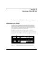
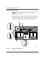
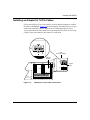
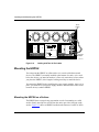
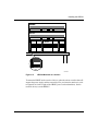
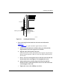
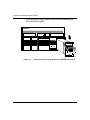
Installing and
Maintaining the HRPSU
Part No. 114312 Rev. C
November 1996
4401 Great America Parkway
Santa Clara, CA 95054
8 Federal Street
Billerica, MA 01821
Copyright © 1988–1996 Bay Networks, Inc.
All rights reserved. Printed in the USA. November 1996.
The information in this document is subject to change without notice. The statements, configurations, technical data,
and recommendations in this document are believed to be accurate and reliable, but are presented without express or
implied warranty. Users must take full responsibility for their applications of any products specified in this document.
The information in this document is proprietary to Bay Networks, Inc.
The software described in this document is furnished under a license agreement and may only be used in accordance
with the terms of that license. A summary of the Software License is included in this document.
Restricted Rights Legend
Use, duplication, or disclosure by the United States Government is subject to restrictions as set forth in subparagraph
(c)(1)(ii) of the Rights in Technical Data and Computer Software clause at DFARS 252.227-7013.
Notice for All Other Executive Agencies
Notwithstanding any other license agreement that may pertain to, or accompany the delivery of, this computer
software, the rights of the United States Government regarding its use, reproduction, and disclosure are as set forth in
the Commercial Computer Software-Restricted Rights clause at FAR 52.227-19.
Trademarks of Bay Networks, Inc.
ACE, AFN, AN, BCN, BLN, BN, BNX, CN, FN, FRE, GAME, LN, Optivity, PPX, SynOptics, SynOptics
Communications, Wellfleet and the Wellfleet logo are registered trademarks and ANH, ASN, Bay•SIS, BCNX,
BLNX, EZ Install, EZ Internetwork, EZ LAN, PathMan, PhonePlus, Quick2Config, RouterMan, SPEX,
Bay Networks, Bay Networks Press, the Bay Networks logo and the SynOptics logo are trademarks of
Bay Networks, Inc.
Third-Party Trademarks
All other trademarks and registered trademarks are the property of their respective owners.
Statement of Conditions
In the interest of improving internal design, operational function, and/or reliability, Bay Networks, Inc. reserves the
right to make changes to the products described in this document without notice.
Bay Networks, Inc. does not assume any liability that may occur due to the use or application of the product(s) or
circuit layout(s) described herein.
Portions of the code in this software product are Copyright © 1988, Regents of the University of California. All rights
reserved. Redistribution and use in source and binary forms of such portions are permitted, provided that the above
copyright notice and this paragraph are duplicated in all such forms and that any documentation, advertising materials,
and other materials related to such distribution and use acknowledge that such portions of the software were
developed by the University of California, Berkeley. The name of the University may not be used to endorse or
promote products derived from such portions of the software without specific prior written permission.
SUCH PORTIONS OF THE SOFTWARE ARE PROVIDED “AS IS” AND WITHOUT ANY EXPRESS OR
IMPLIED WARRANTIES, INCLUDING, WITHOUT LIMITATION, THE IMPLIED WARRANTIES OF
MERCHANTABILITY AND FITNESS FOR A PARTICULAR PURPOSE.
In addition, the program and information contained herein are licensed only pursuant to a license agreement that
contains restrictions on use and disclosure (that may incorporate by reference certain limitations and notices imposed
by third parties).
ii
114312 Rev. C
USA Requirements Only
Federal Communications Commission (FCC) Compliance Notice: Radio Frequency Notice
This equipment generates, uses, and can radiate radio-frequency energy. If you do not install and use this equipment
according to the instruction manual, this product may interfere with radio communications. This product has been
tested and found to comply with the limits for a Class A computing device, pursuant to Subpart J of Part 15 of FCC
Rules. Operation is subject to the following two conditions: (1) this device may not cause harmful interference, and
(2) this device must accept any interference received, including interference that may cause undesired operation.
Operating this equipment in a residential area is likely to interfere with radio communications; in which case, the user,
at his/her own expense, must correct the interference.
Shielded-compliant cables must be used with this unit to ensure compliance with the Class A limits.
EN 55 022 Declaration of Conformance
This is to certify that the Bay Networks products in this book are shielded against the generation of radio interference
in accordance with the application of Council Directive 89/336/EEC, Article 4a. Conformity is declared by the
application of EN 55 022:1987 Class A (CISPR 22:1985/BS 6527:1988).
114312 Rev. C
iii
Japan/Nippon Requirements Only
Voluntary Control Council for Interference (VCCI) Statement
Voluntary Control Council for Interference (VCCI) Statement
This equipment is in the 1st category (information equipment to be used in commercial and/or industrial areas) and
conforms to the standards set by the Voluntary Control Council for Interference by Data Processing Equipment and
Electronic Office Machines that are aimed at preventing radio interference in commercial and/or industrial areas.
Consequently, when this equipment is used in a residential area or in an adjacent area thereto, radio interference may
be caused to equipment such as radios and TV receivers.
Compliance with the applicable regulations is dependent upon the use of shielded cables. The user is responsible for
procuring the appropriate cables. Read instructions for correct handling.
iv
114312 Rev. C
Bay Networks Software License
Note: This is Bay Networks basic license document. In the absence of a
software license agreement specifying varying terms, this license -- or the
license included with the particular product -- shall govern licensee’s use of
Bay Networks software.
This Software License shall govern the licensing of all software provided to licensee by Bay Networks (“Software”).
Bay Networks will provide licensee with Software in machine-readable form and related documentation
(“Documentation”). The Software provided under this license is proprietary to Bay Networks and to third parties from
whom Bay Networks has acquired license rights. Bay Networks will not grant any Software license whatsoever, either
explicitly or implicitly, except by acceptance of an order for either Software or for a Bay Networks product
(“Equipment”) that is packaged with Software. Each such license is subject to the following restrictions:
1.
Upon delivery of the Software, Bay Networks grants to licensee a personal, nontransferable, nonexclusive license
to use the Software with the Equipment with which or for which it was originally acquired, including use at any
of licensee’s facilities to which the Equipment may be transferred, for the useful life of the Equipment unless
earlier terminated by default or cancellation. Use of the Software shall be limited to such Equipment and to such
facility. Software which is licensed for use on hardware not offered by Bay Networks is not subject to restricted
use on any Equipment, however, unless otherwise specified on the Documentation, each licensed copy of such
Software may only be installed on one hardware item at any time.
2.
Licensee may use the Software with backup Equipment only if the Equipment with which or for which it was
acquired is inoperative.
3.
Licensee may make a single copy of the Software (but not firmware) for safekeeping (archives) or backup
purposes.
4.
Licensee may modify Software (but not firmware), or combine it with other software, subject to the provision
that those portions of the resulting software which incorporate Software are subject to the restrictions of this
license. Licensee shall not make the resulting software available for use by any third party.
5.
Neither title nor ownership to Software passes to licensee.
6.
Licensee shall not provide, or otherwise make available, any Software, in whole or in part, in any form, to any
third party. Third parties do not include consultants, subcontractors, or agents of licensee who have licensee’s
permission to use the Software at licensee’s facility, and who have agreed in writing to use the Software only in
accordance with the restrictions of this license.
7.
Third-party owners from whom Bay Networks has acquired license rights to software that is incorporated into
Bay Networks products shall have the right to enforce the provisions of this license against licensee.
8.
Licensee shall not remove or obscure any copyright, patent, trademark, trade secret, or similar intellectual
property or restricted rights notice within or affixed to any Software and shall reproduce and affix such notice on
any backup copy of Software or copies of software resulting from modification or combination performed by
licensee as permitted by this license.
114312 Rev. C
v
Bay Networks Software License (continued)
9.
Licensee shall not reverse assemble, reverse compile, or in any way reverse engineer the Software. [Note: For
licensees in the European Community, the Software Directive dated 14 May 1991 (as may be amended from time
to time) shall apply for interoperability purposes. Licensee must notify Bay Networks in writing of any such
intended examination of the Software and Bay Networks may provide review and assistance.]
10. Notwithstanding any foregoing terms to the contrary, if licensee licenses the Bay Networks product “Site
Manager,” licensee may duplicate and install the Site Manager product as specified in the Documentation. This
right is granted solely as necessary for use of Site Manager on hardware installed with licensee’s network.
11. This license will automatically terminate upon improper handling of Software, such as by disclosure, or Bay
Networks may terminate this license by written notice to licensee if licensee fails to comply with any of the
material provisions of this license and fails to cure such failure within thirty (30) days after the receipt of written
notice from Bay Networks. Upon termination of this license, licensee shall discontinue all use of the Software
and return the Software and Documentation, including all copies, to Bay Networks.
12. Licensee’s obligations under this license shall survive expiration or termination of this license.
vi
114312 Rev. C
Chapter 1
Overview of the HRPSU
This chapter describes the HRPSU (High Power Redundant Power Supply Unit)
power rack and power supply module, and describes preparing for installation.
Introduction to the HRPSU
The HRPSU is a hot-swappable power supply that provides uninterrupted
operation to network devices in the event of a network device power supply
failure. The HRPSU is a standalone unit that can support up to four network
devices equipped with redundant power supply outlets.
The HRPSU is a modular system consisting of a power rack (Order No.
AA0002001) with slots for four power supply modules (Order No. AA0005003).
You can install as many modules as needed, between one and four, in the power
rack. Figure 1-1 shows an HRPSU with all four power supply modules installed.
Redunant
Redunant
Redunant
Redunant
AC Power Module
AC Power Module
AC Power Module
AC Power Module
Power OK
Power OK
Power OK
Power OK
HRP0001A
Figure 1-1.
114312 Rev. C
HRPSU (High Power Redundant Power Supply Unit)
1-1
Installing and Maintaining the HRPSU
The HRPSU supports devices requiring up to 210 watts of power, as well as those
with lower power requirements. Each power supply module in the HRPSU
operates independently. For example, if you need to replace a power supply
module, you can turn off that module’s power switch, leaving the other modules
operational.
Figure 1-2 shows the front of the HRPSU with the front panels removed from two
slots, and a power supply module. The blank front panel on each power supply
slot normally remains on the HRPSU until a module is installed. The power
supply module, which has a permanent front panel, is provided with a latch for
handling the module and for keeping it in place during operation.
HRPSU
Power Rack
Power Supply
Module
Backplane
Flange
Blank front
panels
Hot Swap
connector
Latch
Access barrier
HRP0003A
Figure 1-2.
1-2
HRPSU Power Rack and Power Supply Module
114312 Rev. C
Overview of the HRPSU
Hot-swap connectors on each power supply module connect the input and output
signals of the power supply to the power rack backplane. The hot-swappable
feature allows you to install the HRPSU without turning off the power to the
network devices. Redundancy is provided with no down-time on the network.
A safety door inside each power supply slot prevents hands or other objects from
touching the connector on the backplane. In Figure 1-2, the open slot on the right
shows a safety door in locked position. The open slot on the left shows the power
supply connector on the backplane.
When you insert a power supply module into the slot, the flange on the rear of the
module releases the safety door, allowing the module to connect to the backplane.
The module’s power switch, located on the front panel, is recessed deeply to
prevent you from accidentally turning off the module.
Figure 1-3 shows the rear of the HRPSU power rack. Each power supply slot is
identified by a number (1 - 4) stamped into the metal at the back upper edge of the
HRPSU power rack.
Connector
Standoffs
24-Pin Output Connector
Power Supply
Module ID numbers
4
3
2
UL
1
UL
AC
Power Plug
AC
Power Switch
HRP0002A
Figure 1-3.
114312 Rev. C
Rear View of HRPSU
1-3
Installing and Maintaining the HRPSU
For network devices that use 16-pin cables, you must install a connector adapter to
attach the cable to the HRPSU.
Depending on the particular network device type, the HRPSU attaches to network
devices using 16-pin cables or 24-pin cables. For example:
•
The ASN uses a single 24-pin cable.
•
BayStack and Distributed 5000 device’s use a single 16-pin cable.
•
The 28000 family devices use two 16-pin cables.
Standoffs are provided for 24-pin cable connections, and for attaching 16-pin
adapters for those network devices using 16-pin cables. Once all cabling is
complete and the AC power is turned on, the HRPSU is enabled; signals
automatically sent to the network device inform it of the presence of the HRPSU
-- no other setup is required.
The HRPSU power switch turns off all power to the unit. The AC power cord
plugs into a wall outlet. This allows the network device to have an AC power
source separate from the HRPSU. The HRPSU requires a dedicated 15-A branch
circuit for 120-V AC power service.
North American and Japanese users need to use the Bay Networks 15-A power
cords for their countries (Order Nos. AA0018020 and AA0020001, respectively).
All other countries use the standard Bay Networks 10-A power cord, at 240 V AC,
for their particular country.
Preparing for Installation
Before you install the HRPSU:
•
Check your shipment.
-
Verify that the items you received match the packing list attached to
the shipping container.
-
Inspect all items for damage.
If any parts are missing or damaged, contact the Bay Networks Technical
Response Center for assistance.
•
1-4
Make sure that your site meets the electrical requirements described in
Appendix A.
114312 Rev. C
Overview of the HRPSU
•
Review the installation procedures in Chapter 2. Read all safety sheets
included with the shipment, and the caution and warning labels on the unit.
Observe all safety precautions.
A Phillips screwdriver is required for some installation procedures.
114312 Rev. C
1-5
Chapter 2
Installing the HRPSU
This chapter describes
•
Cabling options for network devices
•
Mounting the HRPSU in a surface stack or in a rack
•
Installing power supply modules in the HRPSU
•
Installing an adapter for 16-pin cables
•
Connecting a network device to the HRPSU
•
Switching on and verifying power connection
Cabling Options
There are three options for cabling a network device to an HRPSU power supply
module. Table 2-1 explains the options and indicates the figure that illustrates each
one.
Depending on your network device, you will use 24-pin cables, or 16-pin cables
with an adapter. Refer to the figure for the cabling option that applies to your
device.
Table 2-1.
114312 Rev. C
Options for Cabling a Network Device
To Connect
Cable Type
Number of
Cables
Used
Figure Number
ASN
24-Pin
1
Figure 2-1
5000 Device
16-Pin
1
Figure 2-3
28000 Device
16-Pin
2
Figure 2-4
2-1
Installing and Maintaining the HRPSU
Using One 24-Pin Cable
Figure 2-1 shows the cabling between a single 24-pin redundant power connector
on a network device and one HRPSU power supply module. This type of
connection provides up to 210 W.
Notice that the connector ends are different. The end with end-to-end screws
attaches to the network device; the end with offset screws attaches to the HRPSU.
An EMI gasket is supplied with the cable (see figure). You place the gasket over
the connector on the power supply module before you plug in the cable.
24-pin
cable
End to End
screws
PHY
1
SD
TX
B
S
B
Y
P
A
S
S
FDDI-MM
34003
PHY
A
SD
TX
F
P
2
2
1
DCD
DCD
SYNC
1
34001
F
3
OUT
ETHERNET
34000
XMT/RCV
2
F
CONSOLE
SPEX
SLOT
3
4
2
UL
1
UL
Offset
screws
EMI gasket
HRP0011A
Figure 2-1.
2-2
Cabling with One 24-Pin Cable
114312 Rev. C
Installing the HRPSU
Installing an Adapter for 16-Pin Cables
If your network device uses 16-pin cables, you must install an adapter to connect
the cable to the HRPSU. Figure 2-2 shows an adapter. The adapter has two 16-pin
connections, labeled P1 and P2. Network devices that require the use of two
16-pin cables attach to both connections on the adapter (P1 and P2); devices using
a single 16-pin cable attach to the bottom (P1) connection.
P2
16-pin
Connector Adapter
P1
Adapter
standoff
P2
2
1
Captive
screw
P1
Figure 2-2.
114312 Rev. C
Adapter for 16-Pin Cable Connections
2-3
Installing and Maintaining the HRPSU
Note: By default, the adapter for 16-pin cable connections is shipped with a
protective cover over the P2 connection. If your network device requires two
16-pin connections, you must remove this cover before attempting to attach
the second network device cable.
You can install up to four adapters on the HRPSU; however, only one network
device may be attached to each adapter.
Note: If there is an EMI gasket on the 24-pin connector, remove it first.
2-4
1.
Place the adapter over any 24-pin output connector on the HRPSU, as
shown in Figure 2-2, and firmly press the 16-pin adapter connector into
the HRPSU 24-pin connector.
2.
Insert and tighten the captive screw supplied for the adapter.
114312 Rev. C
Installing the HRPSU
Using One 16-Pin Cable
Figure 2-3 shows the cabling between a single 16-pin redundant power connector
on a network device and an HRPSU power supply module using an adapter. This
type of connection provides up to 130 W.
16-pin
cable
UL
Redundant Power
100-240~
1.2A
50-60Hz
UL
Console
2
4
UL
Modem
1
UL
P2
Connector
adapter
P1
HRP0015A
Figure 2-3.
Cabling with One 16-Pin Cable
Note: When using a single 16-pin cable, plug the cable into the lower
connector on the adapter (P1).
Using Two 16-Pin Cables
Figure 2-4 shows the cabling between two 16-pin redundant power connectors on
a network device and an HRPSU power supply module using an adapter. This type
of connection provides up to 210 W.
114312 Rev. C
2-5
Installing and Maintaining the HRPSU
16-Pin
Cables
3
4
2
UL
1
UL
P2
P1
Connector
Adapter
HRP0014A
Figure 2-4.
Cabling with Two 16-Pin Cables
Mounting the HRPSU
You can mount the HRPSU on a flat surface or in a stack with other network
devices. The HRPSU is normally installed at the bottom of a stack, or in a rack
below the devices you intend to attach to it. Your only restriction (as far as where
you place the HRPSU) is the length of cabling necessary to attach the device.
You mount the HRPSU before installing the power supply modules. Once it is in
place, you install all of your power supply modules, then attach the cables to the
network device(s) and the HRPSU.
Mounting the HRPSU on a Surface
The HRPSU does not require any preparation or tools for mounting on a solid
surface. Sturdy non-slip feet are built into the unit to provide a firm grip on the
surface. Figure 2-5 shows an HRPSU installed at the bottom of a stack of ASNs.
2-6
114312 Rev. C
Installing the HRPSU
Access Stack Node
RUN
BOOT
POWER
Access Stack Node
RUN
BOOT
POWER
Non-Slip
feet
HRP0005A
Figure 2-5.
HRPSU Mounted on a Surface
To mount the HRPSU under a stack of devices, place the unit on a surface that will
support the power supply and the network devices you intend to attach to it (refer
to Appendix A for the weight of the HRPSU power rack and modules). Set the
network device(s) on the HRPSU.
114312 Rev. C
2-7
Installing and Maintaining the HRPSU
Mounting the HRPSU in a Rack
This procedure requires
•
Three hardware packages from the HRPSU shipment. The packages you need
contain the angle brackets, flanges, mounting screws, and cagenuts.
•
A Phillips screwdriver.
•
An electronic enclosure rack that meets the specifications listed in Table A-1,
Appendix A.
When you have the required equipment, to install the HRPSU in a rack:
1.
Measure at least 5.25 in. (13.3 cm) of free vertical space inside the rack.
If you plan to stack the HRPSU with ASNs, multiply 5.25 in. by the number
of nodes in the stack. Then make sure the rack has enough (contiguous) free
vertical space for the stack.
2.
Locate the nearest two rail holes, below the area you just measured, that
are 0.50 in. (1.27 cm) apart.
The hole in the flange that you install on the HRPSU (in Step 4) will align
with the rail holes as shown in Figure 2-6.
2-8
114312 Rev. C
Installing the HRPSU
Flange
Rack post
0.625"
0.500"
Mounting hole locations
Angle bracket
supporting router
mounted on back of
rack post
ASN0001A
Figure 2-6.
3.
Locating the Rail Holes
Insert each angle bracket inside the rack in the area indicated in
Figure 2-7.
Using Figure 2-7 as a guide, attach the angle brackets as follows:
a.
If there are no threads in the rail holes where you will attach the
angle brackets, insert four cagenuts over the holes.
b.
Align the edge of the bracket to the rack.
If the interior of the rack has horizontal bracket supports, align the angle
brackets with the supports. Otherwise, brace the angle brackets between
the side rails.
c.
Insert a 10-32 screw through the slots at each end of the bracket and
into the holes in the rack supports. Do not tighten the screws.
d. Adjust each bracket vertically along the bracket slots until the
bracket is 0.78 in. (1.98 cm) below the center of one hole in the front
vertical support of the rack.
e.
114312 Rev. C
Tighten the screws with a Phillips screwdriver.
2-9
Installing and Maintaining the HRPSU
Access Stack Node
Run
Remote Power
Local Power
Boot
Diag
Height:
5.25 in. (13.3 cm) minimum
Depth
19.5 in. (49.5 cm) minimum
Screws
(2 places)
Bracket
(2 places)
Rail
Cagenut
If rack rail is
not threaded,
attach cagenut.
ASN0004A
Figure 2-7.
2-10
Attaching Angle Brackets
114312 Rev. C
Installing the HRPSU
4.
Refer to Figure 2-8 and attach each flange to the HRPSU as follows.
•
When the HRPSU is to be mounted to single posts (center-of-gravity
mount), attach the brackets with the flange facing the rear of the HRPSU,
as shown on the left.
•
When the HRPSU is to be mounted to double posts (flush mounted, as in
Figure 2-8), reverse the brackets, as shown on the right in Figure 2-8. The
front of the HRPSU will be flush with the rack-mounted network devices.
Screws
(8 places)
HRP0006A
Figure 2-8.
5.
Attaching Flanges to the ASN
Place the HRPSU on the angle brackets in the rack. Align the flange holes
with the holes in the front vertical supports on the rack (Figure 2-9).
If the rack holes are not threaded, place cagenuts over them.
114312 Rev. C
2-11
Installing and Maintaining the HRPSU
RUN
BOOT
Access Stack Node
DIAG
POWER
Cage-Nut screw
(4 places)
Rail without
threaded holes
use Cage-Nut
HRP0007A
Figure 2-9.
2-12
Mounting the HRPSU in an Enclosure Rack
6.
Insert a 10-32 screw through each flange hole and into the corresponding
holes in the front vertical supports of the rack.
7.
Tighten the screws with a Phillips screwdriver.
114312 Rev. C
Installing the HRPSU
Installing a Power Supply Module in the HRPSU Power Rack
The HRPSU power rack and the power supply modules are packaged separately.
You must install the power supply modules in the HRPSU power rack. You can fill
the slots in any order. Figure 2-10 shows a power supply module being inserted
into the HRPSU power rack.
Access Stack Node
RUN
BOOT
POWER
Redunant
AC Power Module
Power OK
HRP0009A
Figure 2-10.
Inserting Power Supply Module in HRPSU Power Rack
Install the power supply module using the following steps:
1.
From any slot, remove the blank front panel as follows: with your fingers
under the top edge of the panel, pull outward. Discard the panel.
2.
Lift the latch of the power supply module and slide the module straight
into the slot between the side rails. The flange on the back of the module
releases the safety door as the module pushes the door up.
When the module cannot go any farther, it is connected to the backplane.
3.
114312 Rev. C
Push the latch down firmly to lock the module in place.
2-13
Installing and Maintaining the HRPSU
Connecting Cables and Switching on Power
When you have installed the power supply modules in the HRPSU power rack,
you can connect the network devices to the HRPSU. For best results, connect all
cables and turn on the power switches in the following order:
Note: The network device power does NOT have to be turned off for this
procedure.
1.
Using the cabling option that applies to your system (see Figures 2-1 through
2-4), plug the cable(s) into the network device(s) that will attach to the
HRPSU.
2.
Tighten the captive screws.
Note: A power module must be in the same slot as the cable.
2-14
3.
If you are using a 24-pin cable, place an EMI gasket over the connector (see
Figure 2-1) before attaching a cable to the HRPSU.
4.
Plug the cable(s) into the HRPSU and tighten the captive screws.
5.
When all cables are plugged in, plug the HRPSU AC power cord into the
HRPSU and into a wall outlet.
6.
Turn on the power switch on the back of the HRPSU power rack.
7.
Turn on the power switch to each power supply module being used. (The
switch does not have to be on for any module not being used.)
114312 Rev. C
Installing the HRPSU
8.
Verify that the power is on by checking the LED on each HRPSU power
supply module being used, and the redundant power supply LED on the
network device(s). Refer to Table 2-2 for the meaning of the status indicators.
Table 2-2.
Status Indicators
LED
Color
Meaning
HRPSU
Module:
Power OK
Green
The HRPSU is capable of sending power to the network
device if needed.
Dark
The HRPSU is not connected to the network device.
Network
Device:
Redundant
Power LED
Green
The device is connected to the HRPSU and can receive
power if needed.
Dark
The network device is not connected to the HRPSU.
Network
Device:
Fan LED*
Amber
A fan has stopped in the network device or in an HRPSU
power supply module.
Dark
All fans are functioning.
*Note: Not all network devices have a fan LED.
If the Power Module Doesn’t Turn On
114312 Rev. C
1.
Make sure that the power switch on the front of all power supply modules
being used is On. (The switches on unused power supply modules do not have
to be on.)
2.
Make sure that the power cord is plugged in to the HRPSU and the wall outlet,
and that the AC power switch on the rear of the HRPSU is ON.
3.
Make sure that all connections are tight.
4.
Turn off the power supply modules power switch and turn it on again to reset
the power supply module.
2-15
Chapter 3
Maintaining the HRPSU
The HRPSU requires little maintenance. You should not open the HRPSU chassis.
If you have any problems, please call a qualified technician.
Danger: Due to high energy hazards, only qualified service personnel are
permitted to install or replace components inside the HRPSU chassis.
Replacing a Power Supply Module in the HRPSU
You can easily replace a power supply module in the HRPSU power rack if
necessary. The power on the HRPSU and the Network Devise(s) can stay on, and
the cables can be left in place for this procedure.
Figure 3-1 shows a power supply module with the latch lifted.
Replace a power supply module using the following steps:
114312 Rev. C
1.
Turn off the power supply switch on the front of the HRPSU module to be
replaced.
2.
Lift the latch on the front of the module, and using it as a handle, pull the
module straight out of the slot. When the module is removed, the safety
door falls shut and locks into place.
3.
Lift the latch of the new power supply module and slide the module
straight into the slot between the side rails. The flange on the back of the
module releases the safety door as the module pushes the door up.
4.
When the module cannot go any farther, it is connected to the backplane.
Push the latch down firmly to lock the module in place.
3-1
Installing and Maintaining the HRPSU
5.
Turn on the power supply module’s switch and verify that the green
Power OK LED is lighted.
Access Stack Node
RUN
BOOT
POWER
Redunant
AC Power Module
Redunant
AC Power Module
Power OK
Power OK
Latch
HRP0004A
Figure 3-1.
3-2
Removing Power Supply Module from HRPSU Power Rack
114312 Rev. C
Appendix A
Technical Specifications
Table A-1.
Physical Specifications
HRPSU Power Rack
Power Supply Module
Table A-2.
Weight:
(H) 5.25 in. by (W) 17.5 in. by (D) 17 in.
(H) 13.33 cm by (W) 44.45 cm by (D) 43.18 cm
20 lb (9.08 kg)
Weight:
5.15 lb (2.34 kg)
Environmental Requirements
Operating temperature
10˚ to 40˚ C
Cooling
12-V DC ball-bearing fan inside each power supply module
Table A-3.
114312 Rev. C
Dimensions:
Wall Receptacle Requirements
Country
Receptacle
Voltage
North America and
Japan
National Electrical Manufacturers
Association (NEMA)
10 A, 200 - 240 V
15 A, 100 - 120 V
Any other country
Standard wall receptacle
200 - 240 V
A-1
Installing and Maintaining the HRPSU
Table A-4.
Electrical
A-2
Electrical Specifications
Line frequency:
47 to 63 Hz
Voltage amperes rating:
1200 VA
Input power:
1150 W
Input voltage:
100 to 240 V
Input current rating:
12 - 7 A
Output voltages:
+5 V @ 40 A
+12 V @ 4.5 A
-12 V @ 0.5 A
Safety agencies
UL-listed
Certified to CSA standards
TUV-licensed
Thermal rating
4000 BTU maximum, fully powered chassis
114312 Rev. C
About This Guide
This guide explains how to mount, install, and maintain a Bay Networks™
HRPSU (High Power Redundant Power Supply Unit), and how to connect it to
network devices.
This guide assumes that you have experience installing computer equipment.
Related Documentation
For information about the network devices that can attach to the HRPSU, see the
Bay Networks home page on the World Wide Web. The Bay Networks URL is
http://www.baynetworks.com.
For information about your particular network device, refer to the manual that was
supplied with it.
Ordering Bay Networks Publications
To purchase additional copies of this document or other Bay Networks
publications, order by part number from the Bay Networks Press™ at the following
telephone or fax numbers:
• Telephone - U.S./Canada
• Telephone - International
• Fax
1-888-4BAYPRESS
1-510-490-4752
1-510-498-2609
You can also use these numbers to request a free catalog of Bay Networks Press
product publications.
114312 Rev. C
xiii
Figures
Figure 1-1.
Figure 1-2.
Figure 1-3.
Figure 2-1.
Figure 2-2.
Figure 2-3.
Figure 2-4.
Figure 2-5.
Figure 2-6.
Figure 2-7.
Figure 2-8.
Figure 2-9.
Figure 2-10.
Figure 3-1.
114312 Rev. C
HRPSU (High Power Redundant Power Supply Unit) ..............................1-1
HRPSU Power Rack and Power Supply Module ......................................1-2
Rear View of HRPSU ...............................................................................1-3
Cabling with One 24-Pin Cable ................................................................2-2
Adapter for 16-Pin Cable Conections ......................................................2-3
Cabling with One 16-Pin Cable ................................................................2-5
Cabling with Two 16-Pin Cables ...............................................................2-6
HRPSU Mounted on a Surface ................................................................2-7
Locating the Rail Holes ............................................................................2-9
Attaching Angle Brackest .......................................................................2-10
Attaching Flanges to the HRPSU............................................................2-11
Mounting the HRPSU in an Enclosure Rack...........................................2-12
Inserting Power Supply Module in HRPSU Power Rack.........................2-13
Removing Power Supply Module from HRPSU Power Rack ...................3-2
ix
Tables
Table 2-1.
Table 2-2
Table A-1.
Table A-2.
Table A-3.
Table A-4.
114312 Rev. C
Options for Cabling a Network Device ......................................................2-1
Status Indicators ....................................................................................2-15
Physical Specifications ........................................................................... A-1
Environmental Requirements .................................................................. A-1
Wall Receptacle Requirements ............................................................... A-1
Electrical Specifications .......................................................................... A-2
xi
Contents
About This Guide
Related Documentation ...................................................................................................xiii
Ordering Bay Networks Publications ...............................................................................xiii
Technical Support and Online Services
Bay Networks Customer Service .....................................................................................xvi
Bay Networks Information Services ................................................................................xvii
World Wide Web .......................................................................................................xvii
Customer Service FTP .............................................................................................xvii
Support Source CD ................................................................................................. xviii
CompuServe ........................................................................................................... xviii
InfoFACTS .................................................................................................................xix
How to Get Help ........................................................................................................xix
Chapter 1
Overview of the HRPSU
Introduction to the HRPSU .............................................................................................1-1
Preparing for Installation .................................................................................................1-4
Chapter 2
Installing the HRPSU
Cabling Options ..............................................................................................................2-1
Using One 24-Pin Cable ..........................................................................................2-2
Installing an Adapter for 16-Pin Cables ....................................................................2-3
Using One 16-Pin Cable ...........................................................................................2-4
Using Two 16-Pin Cables ..........................................................................................2-5
Mounting the HRPSU ......................................................................................................2-6
Mounting the HRPSU on a Surface ..........................................................................2-6
Mounting the HRPSU in a Rack ......................................................................................2-8
114312 Rev. C
vii
Installing a Power Supply Module in the HRPSU Power Rack .....................................2-13
Connecting Cables and Switching on Power ................................................................2-14
If the Power Module Doesn’t Turn On .....................................................................2-15
Chapter 3
Maintaining the HRPSU
Replacing a Power Supply Module in the HRPSU .........................................................3-1
Appendix A
Technical Specifications
viii
114312 Rev. C
Technical Support and Online Services
To ensure comprehensive network support to our customers and partners
worldwide, Bay Networks Customer Service has Technical Response Centers
in key locations around the globe:
•
•
•
•
•
Billerica, Massachusetts
Santa Clara, California
Sydney, Australia
Tokyo, Japan
Valbonne, France
The Technical Response Centers are connected via a redundant Frame Relay
Network to a Common Problem Resolution system, enabling them to transmit and
share information, and to provide live, around-the-clock support 365 days a year.
Bay Networks Information Services complement the Bay Networks Service
program portfolio by giving customers and partners access to the most current
technical and support information through a choice of access/retrieval means.
These include the World Wide Web, CompuServe, Support Source CD, Customer
Support FTP, and InfoFACTS document fax service.
114312 Rev. C
xv
Installing and Maintaining the HRPSU
Bay Networks Customer Service
If you purchased your Bay Networks product from a distributor or authorized
reseller, contact that distributor’s or reseller’s technical support staff for assistance
with installation, configuration, troubleshooting, or integration issues.
Customers can also purchase direct support from Bay Networks through a variety
of service programs. As part of our PhonePlus™ program, Bay Networks Service
sets the industry standard, with 24-hour, 7-days-a-week telephone support
available worldwide at no extra cost. Our complete range of contract and
noncontract services also includes equipment staging and integration, installation
support, on-site services, and replacement parts delivery -- within approximately
4 hours.
To purchase any of the Bay Networks support programs, or if you have questions
on program features, use the following numbers:
Region
Telephone Number
Fax Number
United States and
Canada
1-800-2LANWAN; enter Express Routing
Code (ERC) 290 when prompted
(508) 670-8766
(508) 436-8880 (direct)
Europe
(33) 92-968-300
(33) 92-968-301
Asia/Pacific Region
(612) 9927-8800
(612) 9927-8811
Latin America
(407) 997-1713
(407) 997-1714
In addition, you can receive information on support programs from your local
Bay Networks field sales office, or purchase Bay Networks support directly
from your authorized partner.
xvi
114312 Rev. C
Technical Support and Online Services
Bay Networks Information Services
Bay Networks Information Services provide up-to-date support information as a
first-line resource for network administration, expansion, and maintenance. This
information is available from a variety of sources.
World Wide Web
The Bay Networks Customer Support Web Server offers a diverse library of
technical documents, software agents, and other important technical information
to Bay Networks customers and partners.
A special benefit for contracted customers and resellers is the ability to access the
Web Server to perform Case Management. This feature enables your support staff
to interact directly with the network experts in our worldwide Technical Response
Centers. A registered contact with a valid Site ID can
•
View a listing of support cases and determine the current status of any open
case. Case history data includes severity designation, and telephone, e-mail,
or other logs associated with the case.
•
Customize the listing of cases according to a variety of criteria, including
date, severity, status, and case ID.
•
Log notes to existing open cases.
•
Create new cases for rapid, efficient handling of noncritical network
situations.
•
Communicate directly via e-mail with the specific technical resources
assigned to your case.
The Bay Networks URL is http://www.baynetworks.com. Customer Service is a
menu item on that home page.
Customer Service FTP
Accessible via URL ftp://support.baynetworks.com (134.177.3.26), this site
combines and organizes support files and documentation from across the
Bay Networks product suite, including switching products from our Centillion™
and Xylogics® business units. Central management and sponsorship of this FTP
site lets you quickly locate information on any of your Bay Networks products.
114312 Rev. C
xvii
Installing and Maintaining the HRPSU
Support Source CD
This CD-ROM -- sent quarterly to all contracted customers -- is a complete Bay
Networks Service troubleshooting knowledge database with an intelligent text
search engine.
The Support Source CD contains extracts from our problem-tracking database;
information from the Bay Networks Forum on CompuServe; comprehensive
technical documentation, such as Customer Support Bulletins, Release Notes,
software patches and fixes; and complete information on all Bay Networks
Service programs.
You can run a single version on Macintosh Windows 3.1, Windows 95,
Windows NT, DOS, or UNIX computing platforms. A Web links feature enables
you to go directly from the CD to various Bay Networks Web pages.
CompuServe
For assistance with noncritical network support issues, Bay Networks Information
Services maintain an active forum on CompuServe, a global bulletin-board
system. This forum provides file services, technology conferences, and a message
section to get assistance from other users.
The message section is monitored by Bay Networks engineers, who provide
assistance wherever possible. Customers and resellers holding Bay Networks
service contracts also have access to special libraries for advanced levels of
support documentation and software. To take advantage of CompuServe’s recently
enhanced menu options, the Bay Networks Forum has been re-engineered to allow
links to our Web sites and FTP sites.
We recommend the use of CompuServe Information Manager software to access
these Bay Networks Information Services resources. To open an account and
receive a local dial-up number in the United States, call CompuServe at
1-800-524-3388. Outside the United States, call 1-614-529-1349, or your nearest
CompuServe office. Ask for Representative No. 591. When you are on line with
your CompuServe account, you can reach us with the command GO BAYNET.
xviii
114312 Rev. C
Technical Support and Online Services
InfoFACTS
InfoFACTS is the Bay Networks free 24-hour fax-on-demand service. This
automated system has libraries of technical and product documents designed to
help you manage and troubleshoot your Bay Networks products. The system
responds to a fax from the caller or to a third party within minutes of being
accessed.
To use InfoFACTS in the United States or Canada, call toll-free 1-800-786-3228.
Outside North America, toll calls can be made to 1-408-764-1002. In Europe,
toll-free numbers are also available for contacting both InfoFACTS and
CompuServe. Please check our Web page for the listing in your country.
How to Get Help
Use the following numbers to reach your Bay Networks Technical Response
Center:
114312 Rev. C
Technical Response Center Telephone Number
Fax Number
Billerica, MA
1-800-2LANWAN
(508) 670-8765
Santa Clara, CA
1-800-2LANWAN
(408) 764-1188
Valbonne, France
(33) 92-968-968
(33) 92-966-998
Sydney, Australia
(612) 9927-8800
(612) 9927-8811
Tokyo, Japan
(81) 3-5402-0180
(81) 3-5402-0173
xix