1
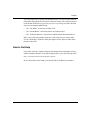
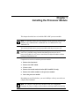
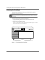
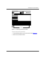
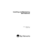
Installing FRE-4-PPC
Processor Modules in BN
Platforms
Part No. 302155-A Rev 00
March 1999
Bay Networks, Inc.
4401 Great America Parkway
Santa Clara, CA 95054
Copyright © 1999 Bay Networks, Inc.
All rights reserved. Printed in the USA. March 1999.
The information in this document is subject to change without notice. The statements, configurations, technical data,
and recommendations in this document are believed to be accurate and reliable, but are presented without express or
implied warranty. Users must take full responsibility for their applications of any products specified in this document.
The information in this document is proprietary to Bay Networks, Inc.
Trademarks
BCN, BLN, BN, FRE, PPX, and Bay Networks are registered trademarks of Bay Networks, Inc.
All other trademarks and registered trademarks are the property of their respective owners.
Statement of Conditions
In the interest of improving internal design, operational function, and/or reliability, Bay Networks, Inc. reserves the
right to make changes to the products described in this document without notice.
Bay Networks, Inc. does not assume any liability that may occur due to the use or application of the product(s) or
circuit layout(s) described herein.
USA Requirements Only
Federal Communications Commission (FCC) Compliance Notice: Radio Frequency Notice
Note: This equipment has been tested and found to comply with the limits for a Class A digital device, pursuant to
Part 15 of the FCC rules. These limits are designed to provide reasonable protection against harmful interference
when the equipment is operated in a commercial environment. This equipment generates, uses, and can radiate radio
frequency energy. If it is not installed and used in accordance with the instruction manual, it may cause harmful
interference to radio communications. Operation of this equipment in a residential area is likely to cause harmful
interference, in which case users will be required to take whatever measures may be necessary to correct the
interference at their own expense.
European Requirements Only
EN 55 022 Statement
This is to certify that the Bay Networks BN is shielded against the generation of radio interference in accordance with
the application of Council Directive 89/336/EEC, Article 4a. Conformity is declared by the application of EN 55 022
Class A (CISPR 22).
Warning: This is a Class A product. In a domestic environment, this product may cause radio interference, in which
case, the user may be required to take appropriate measures.
EC Declaration of Conformity
This product conforms (or these products conform) to the provisions of Council Directive 89/336/EEC and
73/23/EEC. The Declaration of Conformity is available on the Bay Networks World Wide Web site at
www.baynetworks.com.
ii
302155-A Rev 00
Japan/Nippon Requirements Only
Voluntary Control Council for Interference (VCCI) Statement
Voluntary Control Council for Interference (VCCI) Statement
This is a Class A product based on the standard of the Voluntary Control Council for Interference by Information
Technology Equipment (VCCI). If this equipment is used in a domestic environment, radio disturbance may arise.
When such trouble occurs, the user may be required to take corrective actions.
Taiwan Requirements
Bureau of Commodity Inspection Quarantine (BCIQ) Statement
Bureau of Commodity Inspection Quarantine (BCIQ) Statement
Warning: This is a Class A information technology product. In a domestic environment, this product may cause radio
interference, in that case, the user may be required to take appropriate measures.
Canada Requirements Only
Canadian Department of Communications Radio Interference Regulations
This digital apparatus (BN) does not exceed the Class A limits for radio-noise emissions from digital apparatus as set
out in the Radio Interference Regulations of the Canadian Department of Communications.
Règlement sur le brouillage radioélectrique du ministère des Communications
Cet appareil numérique (BN) respecte les limites de bruits radioélectriques visant les appareils numériques de classe
A prescrites dans le Règlement sur le brouillage radioélectrique du ministère des Communications du Canada.
302155-A Rev 00
iii
Bay Networks, Inc. Software License Agreement
NOTICE: Please carefully read this license agreement before copying or using the accompanying software or
installing the hardware unit with pre-enabled software (each of which is referred to as “Software” in this Agreement).
BY COPYING OR USING THE SOFTWARE, YOU ACCEPT ALL OF THE TERMS AND CONDITIONS OF THIS
LICENSE AGREEMENT. THE TERMS EXPRESSED IN THIS AGREEMENT ARE THE ONLY TERMS UNDER
WHICH BAY NETWORKS WILL PERMIT YOU TO USE THE SOFTWARE. If you do not accept these terms and
conditions, return the product, unused and in the original shipping container, within 30 days of purchase to obtain a
credit for the full purchase price.
1. License Grant. Bay Networks, Inc. (“Bay Networks”) grants the end user of the Software (“Licensee”) a personal,
nonexclusive, nontransferable license: a) to use the Software either on a single computer or, if applicable, on a single
authorized device identified by host ID, for which it was originally acquired; b) to copy the Software solely for backup
purposes in support of authorized use of the Software; and c) to use and copy the associated user manual solely in
support of authorized use of the Software by Licensee. This license applies to the Software only and does not extend to
Bay Networks Agent software or other Bay Networks software products. Bay Networks Agent software or other Bay
Networks software products are licensed for use under the terms of the applicable Bay Networks, Inc. Software License
Agreement that accompanies such software and upon payment by the end user of the applicable license fees for such
software.
2. Restrictions on use; reservation of rights. The Software and user manuals are protected under copyright laws. Bay
Networks and/or its licensors retain all title and ownership in both the Software and user manuals, including any
revisions made by Bay Networks or its licensors. The copyright notice must be reproduced and included with any copy
of any portion of the Software or user manuals. Licensee may not modify, translate, decompile, disassemble, use for
any competitive analysis, reverse engineer, distribute, or create derivative works from the Software or user manuals or
any copy, in whole or in part. Except as expressly provided in this Agreement, Licensee may not copy or transfer the
Software or user manuals, in whole or in part. The Software and user manuals embody Bay Networks’ and its licensors’
confidential and proprietary intellectual property. Licensee shall not sublicense, assign, or otherwise disclose to any
third party the Software, or any information about the operation, design, performance, or implementation of the
Software and user manuals that is confidential to Bay Networks and its licensors; however, Licensee may grant
permission to its consultants, subcontractors, and agents to use the Software at Licensee’s facility, provided they have
agreed to use the Software only in accordance with the terms of this license.
3. Limited warranty. Bay Networks warrants each item of Software, as delivered by Bay Networks and properly
installed and operated on Bay Networks hardware or other equipment it is originally licensed for, to function
substantially as described in its accompanying user manual during its warranty period, which begins on the date
Software is first shipped to Licensee. If any item of Software fails to so function during its warranty period, as the sole
remedy Bay Networks will at its discretion provide a suitable fix, patch, or workaround for the problem that may be
included in a future Software release. Bay Networks further warrants to Licensee that the media on which the Software
is provided will be free from defects in materials and workmanship under normal use for a period of 90 days from the
date Software is first shipped to Licensee. Bay Networks will replace defective media at no charge if it is returned to
Bay Networks during the warranty period along with proof of the date of shipment. This warranty does not apply if the
media has been damaged as a result of accident, misuse, or abuse. The Licensee assumes all responsibility for selection
of the Software to achieve Licensee’s intended results and for the installation, use, and results obtained from the
Software. Bay Networks does not warrant a) that the functions contained in the software will meet the Licensee’s
requirements, b) that the Software will operate in the hardware or software combinations that the Licensee may select,
c) that the operation of the Software will be uninterrupted or error free, or d) that all defects in the operation of the
Software will be corrected. Bay Networks is not obligated to remedy any Software defect that cannot be reproduced
with the latest Software release. These warranties do not apply to the Software if it has been (i) altered, except by Bay
Networks or in accordance with its instructions; (ii) used in conjunction with another vendor’s product, resulting in the
defect; or (iii) damaged by improper environment, abuse, misuse, accident, or negligence. THE FOREGOING
WARRANTIES AND LIMITATIONS ARE EXCLUSIVE REMEDIES AND ARE IN LIEU OF ALL OTHER
WARRANTIES EXPRESS OR IMPLIED, INCLUDING WITHOUT LIMITATION ANY WARRANTY OF
MERCHANTABILITY OR FITNESS FOR A PARTICULAR PURPOSE. Licensee is responsible for the security of its
own data and information and for maintaining adequate procedures apart from the Software to reconstruct lost or
altered files, data, or programs.
iv
302155-A Rev 00
4. Limitation of liability. IN NO EVENT WILL BAY NETWORKS OR ITS LICENSORS BE LIABLE FOR ANY
COST OF SUBSTITUTE PROCUREMENT; SPECIAL, INDIRECT, INCIDENTAL, OR CONSEQUENTIAL
DAMAGES; OR ANY DAMAGES RESULTING FROM INACCURATE OR LOST DATA OR LOSS OF USE OR
PROFITS ARISING OUT OF OR IN CONNECTION WITH THE PERFORMANCE OF THE SOFTWARE, EVEN
IF BAY NETWORKS HAS BEEN ADVISED OF THE POSSIBILITY OF SUCH DAMAGES. IN NO EVENT
SHALL THE LIABILITY OF BAY NETWORKS RELATING TO THE SOFTWARE OR THIS AGREEMENT
EXCEED THE PRICE PAID TO BAY NETWORKS FOR THE SOFTWARE LICENSE.
5. Government Licensees. This provision applies to all Software and documentation acquired directly or indirectly by
or on behalf of the United States Government. The Software and documentation are commercial products, licensed on
the open market at market prices, and were developed entirely at private expense and without the use of any U.S.
Government funds. The license to the U.S. Government is granted only with restricted rights, and use, duplication, or
disclosure by the U.S. Government is subject to the restrictions set forth in subparagraph (c)(1) of the Commercial
Computer Software––Restricted Rights clause of FAR 52.227-19 and the limitations set out in this license for civilian
agencies, and subparagraph (c)(1)(ii) of the Rights in Technical Data and Computer Software clause of DFARS
252.227-7013, for agencies of the Department of Defense or their successors, whichever is applicable.
6. Use of Software in the European Community. This provision applies to all Software acquired for use within the
European Community. If Licensee uses the Software within a country in the European Community, the Software
Directive enacted by the Council of European Communities Directive dated 14 May, 1991, will apply to the
examination of the Software to facilitate interoperability. Licensee agrees to notify Bay Networks of any such
intended examination of the Software and may procure support and assistance from Bay Networks.
7. Term and termination. This license is effective until terminated; however, all of the restrictions with respect to
Bay Networks’ copyright in the Software and user manuals will cease being effective at the date of expiration of the
Bay Networks copyright; those restrictions relating to use and disclosure of Bay Networks’ confidential information
shall continue in effect. Licensee may terminate this license at any time. The license will automatically terminate if
Licensee fails to comply with any of the terms and conditions of the license. Upon termination for any reason,
Licensee will immediately destroy or return to Bay Networks the Software, user manuals, and all copies. Bay
Networks is not liable to Licensee for damages in any form solely by reason of the termination of this license.
8. Export and Re-export. Licensee agrees not to export, directly or indirectly, the Software or related technical data
or information without first obtaining any required export licenses or other governmental approvals. Without limiting
the foregoing, Licensee, on behalf of itself and its subsidiaries and affiliates, agrees that it will not, without first
obtaining all export licenses and approvals required by the U.S. Government: (i) export, re-export, transfer, or divert
any such Software or technical data, or any direct product thereof, to any country to which such exports or re-exports
are restricted or embargoed under United States export control laws and regulations, or to any national or resident of
such restricted or embargoed countries; or (ii) provide the Software or related technical data or information to any
military end user or for any military end use, including the design, development, or production of any chemical,
nuclear, or biological weapons.
9. General. If any provision of this Agreement is held to be invalid or unenforceable by a court of competent
jurisdiction, the remainder of the provisions of this Agreement shall remain in full force and effect. This Agreement
will be governed by the laws of the state of California.
Should you have any questions concerning this Agreement, contact Bay Networks, Inc., 4401 Great America Parkway,
P.O. Box 58185, Santa Clara, California 95054-8185.
LICENSEE ACKNOWLEDGES THAT LICENSEE HAS READ THIS AGREEMENT, UNDERSTANDS IT, AND
AGREES TO BE BOUND BY ITS TERMS AND CONDITIONS. LICENSEE FURTHER AGREES THAT THIS
AGREEMENT IS THE ENTIRE AND EXCLUSIVE AGREEMENT BETWEEN BAY NETWORKS AND
LICENSEE, WHICH SUPERSEDES ALL PRIOR ORAL AND WRITTEN AGREEMENTS AND
COMMUNICATIONS BETWEEN THE PARTIES PERTAINING TO THE SUBJECT MATTER OF THIS
AGREEMENT. NO DIFFERENT OR ADDITIONAL TERMS WILL BE ENFORCEABLE AGAINST BAY
NETWORKS UNLESS BAY NETWORKS GIVES ITS EXPRESS WRITTEN CONSENT, INCLUDING AN
EXPRESS WAIVER OF THE TERMS OF THIS AGREEMENT.
302155-A Rev 00
v
Contents
Preface
Before You Begin .............................................................................................................xiii
Text Conventions .............................................................................................................xiv
Acronyms .........................................................................................................................xiv
Bay Networks Technical Publications ..............................................................................xiv
How to Get Help .............................................................................................................. xv
Chapter 1
Installing the Processor Module
Removing the Front Bezel ..............................................................................................1-2
Removing the EMC Shield .............................................................................................1-5
Choosing a Slot ..............................................................................................................1-7
Removing the Board Retainer Bracket (BLN and BLN-2 Only) ......................................1-9
Removing an Airflow Module ..........................................................................................1-9
Removing a Processor Module ....................................................................................1-10
Inserting a Processor Module .......................................................................................1-12
Chapter 2
FRE-4-PPC Module Switch and LEDs
302155-A Rev 00
vii
Figures
Figure 1-1.
Removing the BLN Front Bezel ................................................................1-2
Figure 1-2.
Removing the BLN-2 Front Bezel ............................................................1-3
Figure 1-3.
Removing the BCN Front Bezel ..............................................................1-4
Figure 1-4.
BLN and BCN EMC Shields .....................................................................1-6
Figure 1-5.
Location of Processor Modules and the SRM-F in a BLN or BLN-2 ........1-7
Figure 1-6.
Location of Processor Modules and the SRM-F in a BCN .......................1-8
Figure 1-7.
Airflow Module in a BN Platform ..............................................................1-9
Figure 1-8.
Removing an Airflow Module .................................................................1-10
Figure 1-9.
Using the Extractors to Remove a Processor Module ...........................1-11
Figure 2-1.
FRE-4-PPC Module .................................................................................2-1
302155-A Rev 00
ix
Tables
Table 2-1.
302155-A Rev 00
FRE-4-PPC Processor Module LEDs .....................................................2-2
xi
Preface
The Bay Networks® FRE®-4-PPC processor module is a high-performance fast
routing engine that includes a memory daughterboard and supports the following
FRE-4-PPC link modules:
•
1000BASE-SX Ethernet
•
1000BASE-LX Ethernet
•
10/100BASE-TX Ethernet
•
100BASE-FX Ethernet
Before You Begin
This guide is intended for qualified service personnel who need to install or
replace a FRE-4-PPC processor module in these Backbone Node (BN®)
platforms:
•
Backbone Link Node (BLN®)
•
Backbone Link Node-2 (BLN-2)
•
Backbone Concentrator Node (BCN®)
A qualified service person should have appropriate technical training and
experience and be aware of the hazards involved in installing and replacing
processor modules.
302155-A Rev 00
xiii
Installing FRE-4-PPC Processor Modules in BN Platforms
Text Conventions
This guide uses the following text conventions:
bold text
Indicates command names and options and text that
you need to enter.
Example: Enter the diags command.
italic text
Indicates new terms and book titles.
Acronyms
This guide uses the following acronyms:
DMA
direct memory access
EMC
electromagnetic compatibility
GAME
Gate Access Management Entity
HDCM
Harpoon Diagnostic Console Monitor
ILI
Intelligent Link Interface
LED
light-emitting diode
SRM-F
System Resource Module-Front
Bay Networks Technical Publications
You can now print Bay Networks technical manuals and release notes free,
directly from the Internet. Go to support.baynetworks.com/library/tpubs/. Find the
Bay Networks product for which you need documentation. Then locate the
specific category and model or version for your hardware or software product.
Using Adobe Acrobat Reader, you can open the manuals and release notes, search
for the sections you need, and print them on most standard printers. You can
download Acrobat Reader free from the Adobe Systems Web site,
www.adobe.com.
xiv
302155-A Rev 00
Preface
You can purchase Bay Networks documentation sets, CDs, and selected technical
publications through the Bay Networks Collateral Catalog. The catalog is located
on the World Wide Web at support.baynetworks.com/catalog.html and is divided
into sections arranged alphabetically:
•
The “CD ROMs” section lists available CDs.
•
The “Guides/Books” section lists books on technical topics.
•
The “Technical Manuals” section lists available printed documentation sets.
Make a note of the part numbers and prices of the items that you want to order.
Use the “Marketing Collateral Catalog description” link to place an order and to
print the order form.
How to Get Help
For product assistance, support contracts, information about educational services,
and the telephone numbers of our global support offices, go to the following URL:
http://www.baynetworks.com/corporate/contacts/
In the United States and Canada, you can dial 800-2LANWAN for assistance.
302155-A Rev 00
xv
Chapter 1
Installing the Processor Module
This chapter describes how to install the FRE-4-PPC processor module.
Note: Use the FRE-4-PPC processor module with the following Ethernet link
modules only: 1000BASE-SX, 1000BASE-LX, 10/100BASE-TX, and
100BASE-FX.
You can install and remove processor modules with the power on or off.
Danger: Although you can install and remove processor modules with the
power on, a potential energy hazard exists during hot-swap service of
processor modules. Do not remove more than two adjacent modules without
turning the BN platform off.
Complete these tasks to install the processor module:
1.
Remove the front bezel.
2.
Remove the EMC shield.
3.
Choose a slot.
4.
Remove the board retainer bracket (BLN and BLN-2 only).
5.
Remove the airflow module or the processor module.
6.
Insert the processor module.
Depending on your BN platform, you need a Phillips or flat-tip screwdriver to
complete the installation.
Note: The jumpers on the processor module are not user-configurable.
Changing any jumper settings on this module can disrupt module functioning.
302155-A Rev 00
1-1
Installing FRE-4-PPC Processor Modules in BN Platforms
Removing the Front Bezel
You must remove the front bezel (front cover) of BLN, BLN-2, and BCN
platforms to access their interiors.
Note: Keep the front bezel on during normal operation to comply with airflow
requirements.
To remove the front bezel from the BLN and BLN-2:
1.
Using both hands, pull the bottom of the front bezel forward.
2.
Remove the bezel from the chassis.
Figure 1-1 shows how to remove the bezel from the BLN. Figure 1-2 shows
how to remove the bezel from the BLN-2.
POWER
B A C K B O N E
N O D E
RESET
RUN
BOOT
DIAG
Pull bottom
Figure 1-1.
1-2
ALM0010A
Removing the BLN Front Bezel
302155-A Rev 00
Installing the Processor Module
POWER
B A C K B O N E
N O D E
RUN
BOOT
DIAG
RESET
Pull bottom
ALM0011A
Figure 1-2.
Removing the BLN-2 Front Bezel
To remove the front bezel from the BCN:
302155-A Rev 00
1.
Using both hands, pull the top of the front bezel forward (Figure 1-3).
2.
Remove the bezel from the chassis.
1-3
Installing FRE-4-PPC Processor Modules in BN Platforms
Pull top
POWER
B A C K B O N E
N O D E
RUN
BOOT
DIAG
RESET
ALM0012A
Figure 1-3.
1-4
Removing the BCN Front Bezel
302155-A Rev 00
Installing the Processor Module
Removing the EMC Shield
You must remove the EMC shield to access the slots for processor modules in BN
platforms.
Caution: Do not operate a BN platform with the EMC shield removed for
more than 5 minutes. Without the EMC shield, the BN platform may overheat.
In addition, the BCN contains temperature sensors that may not detect an
overheating condition without the shield in place.
To remove the EMC shield:
1.
Attach an antistatic wrist strap.
BN platforms and link and processor modules ship with an antistatic wrist
strap. You must wear one of these straps whenever you access components in
the platform.
The antistatic wrist strap directs the discharge of static electricity from your
body to the chassis, thereby avoiding discharge and possible damage to
sensitive electronic components.
Caution: Electrostatic discharge can damage hardware. Always use the
antistatic wrist strap when handling any component in your BN platform.
302155-A Rev 00
2.
Loosen the captive thumbscrews that fasten the EMC shield to the chassis
(Figure 1-4).
3.
Remove the EMC shield from the chassis.
1-5
Installing FRE-4-PPC Processor Modules in BN Platforms
.
!
POWER
B A C K B O N E
RUN
BOOT
DIAG
N O D E
RESET
WARNING
VORSICHT!
HIGH ENERGY PRESENT
Power unit OFF and disconnect power cord
BEFORE accessing this product.
Refer to your installation/service manual for instructions
HOCHSPANNUNG!
VOR jeglicher Intervention Gerat
ABSTELLEN und Netzstecker herauszuziehen!
Anleitungen in Installations-/Instandhaltungshandbuch beachten!
ATTENTION
PELIGRO
EQUIPEMENT SOUS HAUTE TENSION
Debrancher le cordon d’alimentation avant
d’enlever le couvercle.
Voir les instructions du fabricant
ALTO TENSION
APAGUESE la unidad y desconectese del tomacrriente
ANTES de abrir la unidad.
Veanse las instrucciones del fabricante en el manual de instalacion/servicio
EMC shield
Thumbscrews
(7 places)
ALM0016A
POWER
B A C K B O N E
N O D E
RUN
BOOT
DIAG
RESET
EMC shield
Thumbscrews
(10 places)
ALM0013A
Figure 1-4.
1-6
BLN and BCN EMC Shields
302155-A Rev 00
Installing the Processor Module
Choosing a Slot
You can install a FRE-4-PPC processor module in the following slots:
•
•
Slots 2 through 5 in the BLN and BLN-2 platforms (Figure 1-5)
Slots 1 through 6 and slots 8 through 14 in the BCN platform (Figure 1-6)
!
POWER
B A C K B O N E
N O D E
RUN
BOOT
DIAG
WARNING
RESET
HIGH ENERGY PRESENT
Power unit OFF and disconnect power cord
BEFORE accessing this product.
Refer to your installation/service manual for instructions
ATTENTION
EQUIPEMENT SOUS HAUTE TENSION
Debrancher le cordon d’alimentation avant
d’enlever le couvercle.
Voir les instructions du fabricant
VORSICHT!
HOCHSPANNUNG!
VOR jeglicher Intervention Gerat
ABSTELLEN und Netzstecker herauszuziehen!
Anleitungen in Installations-/Instandhaltungshandbuch beachten!
PELIGRO
ALTO TENSION
APAGUESE la unidad y desconectese del tomacrriente
ANTES de abrir la unidad.
Veanse las instrucciones del fabricante en el manual de instalacion/servicio
FRE-4-PPC
processor modules
(slots 2-5)
SRM-F
(slot 1)
Extractor
Board retainer bracket
(1 screw)
FR40002A
Figure 1-5.
Location of Processor Modules and the SRM-F in a BLN or BLN-2
302155-A Rev 00
1-7
Installing FRE-4-PPC Processor Modules in BN Platforms
FRE-4-PPC processor modules
(slots 1-6)
SRM-F
(slot 7)
FRE-4-PPC processor modules
(slots 8-14)
POWER
B A C K B O N E
N O D E
RUN
BOOT
DIAG
RESET
Extractor
1
2
3
4
5
6
7
8
9
10 11 12 13 14
FR40005A
Figure 1-6.
1-8
Location of Processor Modules and the SRM-F in a BCN
302155-A Rev 00
Installing the Processor Module
Removing the Board Retainer Bracket (BLN and BLN-2 Only)
If you have a BLN or BLN-2 platform, remove the board retainer bracket shown
in Figure 1-5 on page page 1-7:
1.
Use a screwdriver to remove the screw connecting the board retainer
bracket to the chassis.
2.
Gently pull the bottom of the board retainer bracket to remove it.
Removing an Airflow Module
Bay Networks ships an airflow module in each empty processor module slot in all
BN platforms. Each airflow module directs cool air to the adjacent processor
module.
Figure 1-7 shows the location of an airflow module in slot 5 of a BLN platform. If
the slot in which you want to install the processor module contains an airflow
module, you must first remove it from that slot. If the slot that you want to use
already contains a processor module, see “Removing a Processor Module” on
page page 1-10.
!
POWER
B A C K B O N E
N O D E
RUN
BOOT
DIAG
WARNING
RESET
HIGH ENERGY PRESENT
Power unit OFF and disconnect power cord
BEFORE accessing this product.
Refer to your installation/service manual for instructions
ATTENTION
EQUIPEMENT SOUS HAUTE TENSION
Debrancher le cordon d’alimentation avant
d’enlever le couvercle.
Voir les instructions du fabricant
VORSICHT!
HOCHSPANNUNG!
VOR jeglicher Intervention Gerat
ABSTELLEN und Netzstecker herauszuziehen!
Anleitungen in Installations-/Instandhaltungshandbuch beachten!
PELIGRO
ALTO TENSION
APAGUESE la unidad y desconectese del tomacrriente
ANTES de abrir la unidad.
Veanse las instrucciones del fabricante en el manual de instalacion/servicio
Airflow
module
Extractor
Board retainer bracket
(1 screw)
FR40004A
Figure 1-7.
302155-A Rev 00
Airflow Module in a BN Platform
1-9
Installing FRE-4-PPC Processor Modules in BN Platforms
Pull the front of the airflow module forward to remove it (Figure 1-8).
BACK
BON
E NO
DE
POW
RU ER
N
BO
DIAOT
G
RES
ET
BN0022B
Figure 1-8.
Removing an Airflow Module
Removing a Processor Module
When you remove a processor module, connections to that slot and the services
that slot provides are disrupted. The other processor modules resynchronize their
routing tables after the slot fails to receive packets.
1-10
302155-A Rev 00
Installing the Processor Module
To remove a processor module:
1.
Attach an antistatic wrist strap.
BN platforms and processor modules ship with an antistatic wrist strap. You
must wear one of these straps whenever you access components in the
platform.
The antistatic wrist strap directs the discharge of static electricity from your
body to the chassis, thereby avoiding discharge and possible damage to
sensitive electronic components.
2.
Gently pull the inside of the board extractors at each end of the module
toward you (Figure 1-9).
The extractors swing open, pulling the module out of the backplane
connectors.
3.
Place the module in an antistatic protective bag.
!
HT!
VORSIC
NNUNG!
Gerat
HOCHSPA
R
POWE
T
RESE
to your
ENT
ION ION
ATTENT
TE TENS
n avant
S HAU
en!
en!
ch beacht
ntion zuzieh
herausandbu
er Interve
ecker
jeglich
VOR und Netzst ndhaltungsh
-/Insta
LLEN
ations
ABSTE
in Install
ngen
ING
WARN
cord
GY PRES
t.
ENER disconnect power
tions
HIGH
and ing this produc
l for instruc
unit OFF
manua
PowerBEFORE accessrvice
tion/se
installa
Refer
O
Anleitu
PELIGR
rriente
ION
TENS
ervicio
del tomac
cion/s
ectese .
ALTO
y desconla unidad l de instala
abrir el manua
unidad
ESE la ANTES de nte en
del fabrica
ciones
APAGU
e las
instruc
Veans
SOU d’alimentatio
cle. nt
PEMENTle cordon
le couver
EQUI
cher
er
d’enlev
instruc
Debran
tions
du fabrica
Voir les
RUN
BOOT
DIAG
N E
B O
C K
B A
D E
N O
Extractors
FR40001A
Figure 1-9.
302155-A Rev 00
Using the Extractors to Remove a Processor Module
1-11
Installing FRE-4-PPC Processor Modules in BN Platforms
Inserting a Processor Module
To insert a processor module:
1.
Locate the antistatic wrist strap shipped with the BN platform.
2.
Verify that the cable is attached to the wrist strap.
3.
Place the strap around your wrist.
4.
Adjust the strap to ensure that the metal buckle inside the strap touches
your skin.
5.
Attach the alligator clip to the BN faceplate.
6.
Holding the board extractors open, slide the module into the card guides
of the slot.
When inserting a module into a BLN or BLN-2, lift the middle of the board
slightly and push it gently to ensure that the connector in the middle of the
board engages.
7.
Push the extractors in to lock the board in place.
Note: If the extractors do not lock into place easily, remove the module and
repeat steps 6 and 7.
When you insert the processor module into a slot, and the module determines
that slot power is stable, the module automatically does the following:
8.
•
Executes the startup diagnostics
•
Completes the boot process
Observe the module and front-panel LEDs to determine whether the
FRE-4-PPC module is functioning properly.
Following is a brief description of the LED activation sequence after you
insert a new FRE-4-PPC module. For a complete description of LEDs, see
Chapter 2, “FRE-4-PPC Module Switch and LEDs.”
•
1-12
When you insert a FRE-4-PPC processor module, the DIAG LED turns
on during diagnostics and then turns off if diagnostics determine that the
module is functional. If the DIAG LED does not turn off, contact the Bay
Networks Technical Solutions Center.
302155-A Rev 00
Installing the Processor Module
•
If diagnostics determine that the FRE-4-PPC module is not functional, the
DIAG LED on the front panel and LED 21 on the FRE-4-PPC module
remain on. If this occurs, make sure that the module seats properly in the
BN platform and issue the diags command.
•
If diagnostics determine that the FRE-4-PPC module is functional and
that a link module connects to it, the BN platform also performs
diagnostics on the link module.
Regardless of the results of the link module diagnostics, the BOOT LED
turns on, indicating that the FRE-4-PPC is booting. If the link module or
any of its ports do not function, the link module Fail LED turns on.
9.
If you installed the processor module in a BLN or BLN-2, replace the
board retainer bracket as follows:
a.
Slide the top of the board retainer bracket into its designated ridge
and align the bottom of the bracket with the screw hole at the bottom
of the chassis (Figure 1-5 on page page 1-7).
b.
Use a screwdriver to secure the bracket to the chassis.
10. Replace the EMC shield as follows:
a.
Position the EMC shield in front of the chassis.
b.
Tighten the captive thumbscrews that fasten the EMC shield to the
chassis.
Refer to Figure 1-4 on page page 1-6.
11. Remove the antistatic wrist strap.
12. Replace the front bezel as follows:
a.
Align the mounting retainers on the inside of the bezel with the holes
on the front of the EMC shield.
b.
Push the sides of the bezel into place.
Refer to Figure 1-1 (BLN) on page page 1-2, Figure 1-2 (BLN-2) on page
page 1-3, or Figure 1-3 (BCN) on page page 1-4.
302155-A Rev 00
1-13
Chapter 2
FRE-4-PPC Module Switch and LEDs
The front edge of each FRE-4-PPC processor module has several status LEDs, a
Harpoon Diagnostic Console Monitor (HDCM) button, and a flash memory card
ejector (Figure 2-1). Use the LEDs to verify that the module is operating after
installation.
Group 2
35 34 33 32 3130 29 28 27 26 25 24 23
Group 3
Group 1
37 36
HDCM button
22 21 20 19 18 17 16 15 14 13 12 11 10 9 8 7 6 5 4 3 2 1
Memory card
ejector
FRE-4 motherboard
FR40006A
Figure 2-1.
FRE-4-PPC Module
302155-A Rev 00
2-1
Installing FRE-4-PPC Processor Modules in BN Platforms
Table 2-1 describes the LEDs on the FRE-4-PPC processor module.
Table 2-1.
LED
FRE-4-PPC Processor Module LEDs
Meaning
Group 1
1 through 4
Not used
5 (Green)
Address bus busy
6 (Green)
Address retry
7 (Green)
Data bus busy
8 (Green)
The Technician Interface is running on this slot.
9
Not used
10
Not used
11 through 18
(Green)
When diagnostics are running, LED 11 is on, and LEDs 12
through 18 indicate the current test in hexadecimal notation.
When on, LEDs indicate 1s; when off, LEDs indicate 0s.
When the GAME operating system is executing, GAME uses
these LEDs to count time.
19 (Green)
The FRE-4-PPC processor module is resetting.
20 (Amber)
The FRE-4-PPC processor module is booting.
21 (Red)
The FRE-4-PPC processor module failed.
22 (Green)
The FRE-4-PPC processor module is operating normally.
Group 2
23 (Green)
Link module reset
24 (Green)
I2C memory controller reset
25 (Green)
The Parallel Packet Express (PPX®) is held in reset due to a
hardware or software error. This LED also flashes briefly when the
FRE-4-PPC is reinitialized or reset.
26 (Green)
DMA reset
27 (Green)
The PPX direct memory access (DMA) logic is accessing the
buffer memory.
28 (Green)
The FRE-4-PPC processor module is flow-controlling on PPX D.
29 (Green)
The FRE-4-PPC processor module is flow-controlling on PPX C.
30 (Green)
The FRE-4-PPC processor module is flow-controlling on PPX B.
(continued)
2-2
302155-A Rev 00
FRE-4-PPC Module Switch and LEDs
Table 2-1.
FRE-4-PPC Processor Module LEDs (continued)
LED
Meaning
31 (Green)
The FRE-4-PPC processor module is flow-controlling on PPX A.
32 (Green)
The FRE-4-PPC processor module is transmitting on PPX D.
33 (Green)
The FRE-4-PPC processor module is transmitting on PPX C.
34 (Green)
The FRE-4-PPC processor module is transmitting on PPX B.
35 (Green)
The FRE-4-PPC processor module is transmitting on PPX A.
Group 3
36 (Green)
The FRE-4-PPC processor module is receiving power (2.6 V).
37 (Green)
The FRE-4-PPC processor module is receiving power (3.3 V).
The HDCM button has three functions:
•
Establishes an HDCM session (when pressed for less than 1 second and
released). The HDCM session is for Bay Networks Customer Service
personnel only.
•
Warm-starts the FRE-4-PPC module (during an HDCM session when pressed
for less than 1 second and released).
•
Cold-starts the FRE-4-PPC module (when pressed for more than 1 second and
released, regardless of whether an HDCM session is running).
Note: Use the Technician Interface or Site Manager to reset the FRE-4-PPC
module. Do not use the HDCM button unless Bay Networks Customer Service
personnel instruct you to do so.
302155-A Rev 00
2-3