1
BCM Rls 6.0
Digital Mobility Configuration
Task Based Guide
Digital Mobility Configuration
Copyright © 2010 Avaya Inc.
All Rights Reserved.
Notices
While reasonable efforts have been made to ensure that the information in this document is complete and accurate at
the time of printing, Avaya assumes no liability for any errors. Avaya reserves the right to make changes and
corrections to the information in this document without the obligation to notify any person or organization of such
changes.
Documentation disclaimer
Avaya shall not be responsible for any modifications, additions, or deletions to the original published version of this
documentation unless such modifications, additions, or deletions were performed by Avaya. End User agree to
indemnify and hold harmless Avaya, Avaya’s agents, servants and employees against all claims, lawsuits, demands and
judgments arising out of, or in connection with, subsequent modifications, additions or deletions to this documentation,
to the extent made by End User.
Link disclaimer
Avaya is not responsible for the contents or reliability of any linked Web sites referenced within this site or
documentation(s) provided by Avaya. Avaya is not responsible for the accuracy of any information, statement or
content provided on these sites and does not necessarily endorse the products, services, or information described or
offered within them. Avaya does not guarantee that these links will work all the time and has no control over the
availability of the linked pages.
Warranty
Avaya provides a limited warranty on this product. Refer to your sales agreement to establish the terms of the limited
warranty. In addition, Avaya’s standard warranty language, as well as information regarding support for this product,
while under warranty, is available to Avaya customers and other parties through the Avaya Support Web site:
http://www.avaya.com/support
Please note that if you acquired the product from an authorized reseller, the warranty is provided to you by said reseller
and not by Avaya.
Licenses
THE SOFTWARE LICENSE TERMS AVAILABLE ON THE AVAYA WEBSITE,
HTTP://SUPPORT.AVAYA.COM/LICENSEINFO/ ARE APPLICABLE TO ANYONE WHO DOWNLOADS,
USES AND/OR INSTALLS AVAYA SOFTWARE, PURCHASED FROM AVAYA INC., ANY AVAYA
AFFILIATE, OR AN AUTHORIZED AVAYA RESELLER (AS APPLICABLE) UNDER A COMMERCIAL
AGREEMENT WITH AVAYA OR AN AUTHORIZED AVAYA RESELLER. UNLESS OTHERWISE AGREED
TO BY AVAYA IN WRITING, AVAYA DOES NOT EXTEND THIS LICENSE IF THE SOFTWARE WAS
OBTAINED FROM ANYONE OTHER THAN AVAYA, AN AVAYA AFFILIATE OR AN AVAYA
AUTHORIZED RESELLER, AND AVAYA RESERVES THE RIGHT TO TAKE LEGAL ACTION AGAINST
YOU AND ANYONE ELSE USING OR SELLING THE SOFTWARE WITHOUT A LICENSE. BY INSTALLING,
DOWNLOADING OR USING THE SOFTWARE, OR AUTHORIZING OTHERS TO DO SO, YOU, ON BEHALF
OF YOURSELF AND THE ENTITY FOR WHOM YOU ARE INSTALLING, DOWNLOADING OR USING THE
SOFTWARE (HEREINAFTER REFERRED TO INTERCHANGEABLY AS "YOU" AND "END USER"), AGREE
TO THESE TERMS AND CONDITIONS AND CREATE A BINDING CONTRACT BETWEEN YOU AND VAYA
INC. OR THE APPLICABLE AVAYA AFFILIATE ("AVAYA").
Copyright
Except where expressly stated otherwise, no use should be made of the Documentation(s) and Product(s) provided by
Avaya. All content in this documentation(s) and the product(s) provided by Avaya including the selection, arrangement
and design of the content is owned either by Avaya or its licensors and is protected by copyright and other intellectual
property laws including the sui generis rights relating to the protection of databases. You may not modify, copy,
reproduce, republish, upload, post, transmit or distribute in any way any content, in whole or in part, including any
code and software. Unauthorized reproduction, transmission, dissemination, storage, and or use without the express
written consent of Avaya can be a criminal, as well as a civil offense under the applicable law.
Third Party Components
Certain software programs or portions thereof included in the Product may contain software distributed under third
party agreements ("Third Party Components"), which may contain terms that expand or limit rights to use certain
portions of the Product ("Third Party Terms"). Information regarding distributed Linux OS source code (for those
Products that have distributed the Linux OS source code), and identifying the copyright holders of the Third Party
Components and the Third Party Terms that apply to them is available on the Avaya Support Web site:
http://support.avaya.com/Copyright.
Trademarks
The trademarks, logos and service marks ("Marks") displayed in this site, the documentation(s) and product(s)
provided by Avaya are the registered or unregistered Marks of Avaya, its affiliates, or other third parties. Users are not
permitted to use such Marks without prior written consent from Avaya or such third party which may own the Mark.
Nothing contained in this site, the documentation(s) and product(s) should be construed as granting, by implication,
estoppel, or otherwise, any license or right in and to the Marks without the express written permission of Avaya or the
2
NN40011-036 Issue 1.2 BCM Rls 6.0
Digital Mobility Configuration
applicable third party. Avaya is a registered trademark of Avaya Inc. All non-Avaya trademarks are the property of
their respective owners.
Downloading documents
For the most current versions of documentation, see the Avaya Support. Web site: http://www.avaya.com/support
Contact Avaya Support
Avaya provides a telephone number for you to use to report problems or to ask questions about your product. The
support telephone number is 1-800-242-2121 in the United States. For additional support telephone numbers, see the
Avaya Web site: http://www.avaya.com/support
Copyright © 2010 ITEL, All Rights Reserved
The copyright in the material belongs to ITEL and no part of the material may be
reproduced in any form without the prior written permission of a duly authorised
representative of ITEL.
NN40011-036 Issue 1.2 BCM Rls 6.0
3
Digital Mobility Configuration
Table of Contents
Digital Mobility Configuration ............................................. 5
Overview ................................................................................................................ 5
Flow Chart ............................................................................................................. 6
Digital Mobility Controller ....................................................................................... 7
Installing the DMC ................................................................................................. 7
Wall Mounting .............................................................................................. 8
DMC on to DMC .......................................................................................... 9
Connecting to the BCM ....................................................................................... 10
Installing Base Stations ....................................................................................... 11
Base Station Wiring ................................................................................... 12
Installing the Base Station ......................................................................... 13
BCM DECT Cable Installations Utilizing Structured Cabling ............................... 14
Installing Repeaters.......................................................................................... 14
Installing External Antenna ........................................................................ 16
Programming a Repeater .......................................................................... 18
Configuring the Digital Mobility Controller (DMC)................................................ 27
Connecting to the DMC ............................................................................. 27
Configuring the DMC ................................................................................. 28
Installing the Digital Mobility Controller OAM ............................................ 29
Registering Handsets .......................................................................................... 37
Finding the IPEI number of a Handset ...................................................... 37
Registering a Handset using the DMC OAM ............................................. 39
Subscribing Handsets ............................................................................... 41
Registering a Master Handset using the Handset ..................................... 41
Registering Additional Handsets ............................................................... 42
Avaya Documentation Links ............................................. 44
4
NN40011-036 Issue 1.2 BCM Rls 6.0
Digital Mobility Configuration
Digital Mobility Configuration
Overview
The Digital Mobility System uses Digital Enhanced Cordless Telephony (DECT),
which is a digital wireless technology that has been standardized by the ETSI
(European Telecommunications Standard Institute). Although a European
standard, the technology has spread worldwide with only minor differences to the
frequency band allocated for wireless telephony in different markets.
This guide explains how to install and configure the Digital Mobility System. This
includes the installation and configuration of the following components:
Digital Mobility Controller (DMC)
Digital Mobility Base stations (Radio Fixed Part (RFP))
Digital Mobility Repeaters (Wireless Radio Fixed Part (WRFP))
The guide also provides you with information about:
DMC OAM application: the tool used from your computer to configure,
operate, administer and maintain the wireless subsystem through the
DMC.
Digital Mobility Service Tool: the tool used from your computer to
configure and manage handsets and repeaters.
The DMC OAM application and Digital Mobility Service Tool are separate from
the BCM configuration interface (Element Manager). The DMC is connected to
the BCM via a Digital Station Module (DSM+) and will utilize the required ports on
the DSM+ for each of the required Digital Mobility Handsets.
Required Information
Before configuring the Digital Mobility Controller, you should consider the
following:
Has all of the required telephony programming been completed on the
BCM?
Has a Digital Station Module (DSM+) been provided with spare ports for
the Digital Mobility Handsets?
NN40011-036 Issue 1.2 BCM Rls 6.0
5
Digital Mobility Configuration
Flow Chart
Use this flow chart to determine the recommended procedure for installing and
configuring the Digital Mobility system.
Use this flow chart to determine the recommended procedure for installing and
configuring the Digital Mobility system.
Optional
Install the primary DMC and
connect to the BCM: refer
to the Installing the DMC
section of this guide.
Install the secondary DMC
and connect to the BCM:
refer to the Installing the
DMC section of this guide.
Install the Base Stations
and connect to the DMC:
refer to the Installing Base
Stations section of this
guide.
Install Repeaters and any
required external antenna:
refer to the Installing
Repeaters section of this
guide.
Prepare Handsets for use:
refer to the Configuring
the Digital Mobility
Controller section of this
guide.
6
Install the Base Stations
and connect to the DMC:
refer to the Installing Base
Stations section of this
guide.
Install Repeaters and any
required external antenna:
refer to the Installing
Repeaters section of this
guide.
Prepare Handsets for
registration: refer to the
Configuring the Digital
Mobility Controller section
of this guide.
Using the Service Tool,
programme Repeaters:
refer to the Programming a
Repeater section of this
guide.
Register the handsets for
use refer to the
Registering Handsets
section of this guide.
NN40011-036 Issue 1.2 BCM Rls 6.0
Digital Mobility Configuration
Digital Mobility Controller
Installing the DMC
Rack Mounting
You can install a DMC in the same rack as the other networking equipment and
BCM.
Note: The DMC and the BCM must be within 15 meters of each other.
To rack mount a DMC, you need the optional Rack Mount Kit. This kit provides
the parts you need to mount several DMCs into a standard 19-inch equipment
rack.
1. Determine the location in the rack where you want to install the DMC, and
position the rack mounting tray in the rack.
2. Align the holes in the rack mounting bracket with the holes in the
equipment rack rails.
3. Fasten the rack mounting brackets to the rack using the four rack screws
(supplied).
4. Place the DMC on the rack mount tray so that the DMC feet are in the
depressions in the tray. Move the module forward so the feet are touching
the front side of the depressions.
5. Slide the module back until the DMC feet click in place on the tabs in the
depressions.
6. If you want to further secure the DMC, use four of the plastic screws
supplied with the rack mount kit to attach the DMC to the rack mount tray.
Ensure that the screw holes in the DMC are aligned with the holes in the
NN40011-036 Issue 1.2 BCM Rls 6.0
7
Digital Mobility Configuration
rack mount tray. Then drive the four screws through the holes in the
bottom of the tray and into the screw holes in the bottom of the DMC.
Wall Mounting
The DMC can be wall mounted, in which case a wall mounting kit is required.
It is also recommended to have a plywood backboard two cm thick.
1. Mark the location of the plywood backboard on the wall using a pencil,
then mount the plywood backboard securely to the wall.
2. Place the wall mount bracket on the backboard and use a spirit-level to
check that the wall mount bracket is level.
3. Using the wall mount bracket as a template, mark the location of three of
the wall mount bracket holes on the plywood backboard.
Note: The holes marked 1 and 2 show
the suggested positions in relation to
which hole to use. These are in the order
of preference, so use holes marked 1 in
their suggested locations or holes
numbered 2 as an alternative for the
position of the mounting screws.
4. Install three #10 x 2.5 cm round-head wood screws in the backboard. Do
not tighten the screw heads against the backboard. Leave approximately
0.5 cm of the screw exposed from the backboard.
5. Prepare the wall mount bracket by removing the alignment tabs or the side
breakouts on the cable management door. The following describes what
to remove for each of the installation scenarios.
8
NN40011-036 Issue 1.2 BCM Rls 6.0
Digital Mobility Configuration
a. If this is the only DMC in the system, remove the alignment tabs on
the right side of the wall mount bracket.
b. If this is the first DMC on a system with two DMCs (a linked
system), remove the side breakout from the right side of the cable
management door.
c. If this is the last DMC on a system with two DMCs (a linked
system), remove the alignment tabs and the side breakout from the
left side of the cable management door.
6. Hang the wall mount bracket on the mounting screws making sure that the
bracket is level and the wood screw heads seat fully into the wall mount
slots. Then tighten the wood screws against the wall mount bracket.
7. Align the feet on the DMC with the four holes in the wall mount bracket.
Press the DMC against the wall mount bracket and slide the module down
until it clicks into place. Repeat the necessary steps if you are installing a
second DMC in a linked system.
8. Secure the power supply for the DMC unit in such a way that it is secure
and cannot be accidentally dislodged.
DMC on to DMC
The DMC can also be connected directly one on top of the other.
1. Place the DMC on top of the other DMC. Make sure that the DMC feet are
in the slots on the top of the DMC, and in front of the tabs.
NN40011-036 Issue 1.2 BCM Rls 6.0
9
Digital Mobility Configuration
2. Slide the DMC back until it clicks in place on the tabs
On a flat surface
The DMC can be placed on any flat surface that can safely support the weight of
the module. Though please note do not place anything directly on top of the DMC
(except for another DMC). The DMC requires the ventilation holes to be free of
obstructions to prevent overheating.
To install the DMC on a table or shelf.
1. Attach the four rubber feet to the bottom of the DMC. Position the DMC on
the table or shelf, making sure that enough space is left around the DMC
for ventilation and access to the cables.
2. If the DMC is part of a linked system, you can install the other DMC on top
of, or beside, the existing DMC.
3. Secure the power supply for each unit in such a way that it is secure and
cannot be accidentally dislodged.
Connecting to the BCM
This section describes how to connect the DMC to the BCM through TCM (Time
Compression Multiplexing) loop connections, i.e. digital extension loops.
The TCM loop connector is a 50-pin amphenol connector with eight TCM loops
for the DMC080 and 16 TCM loops for the DMC320. The DMC320 has two
Amphenol connectors which support a total of 32 TCM loops.
10
NN40011-036 Issue 1.2 BCM Rls 6.0
Digital Mobility Configuration
The connection of the DMC to the BCM is Amphenol connector to Amphenol
connector.
Note: The maximum length of TCM loops is 15 meters.
TCM Loop
TIP (Body / Band)
RING (Body / Band)
1
2
3
4
White / Blue
White / Orange
White / Green
White / Brown
Blue / White
Orange / White
Green / White
5
6
7
8
9
10
11
12
White / Slate
Red / Blue
Red / Orange
Red/ Green
Red / Brown
Red / Slate
Black / Blue
Black / Orange
Slate / White
Blue / Red
Orange / Red
Green / Red
Brown / Red
Slate / Red
Blue / Black
Orange / Black
13
14
Black / Green
Black / Brown
Black / Slate
Yellow / Blue
Green / Black
Brown / Black
Slate / Black
Blue / Yellow
15
16
Brown / White
Only the first 8
pairs needed
for a single
DMC080
Installing Base Stations
Before you install Base stations, ensure that a site planner defines the base
station locations (site survey for deployment) and records the base station
information in the host system programming record.
Each base station supports four channels and radio coverage of 50 to 150
metres indoor and 300 to 600 metres outdoor (dependant on site survey and
environment).
Note: You must install all base stations within 1500 meters of the DMC. Always
make a cable delay measurement to ensure seamless handover between base
stations.
Avoid installing base stations on large concrete or marble columns because
these columns affect radio coverage. If possible, place the base station a
minimum of one meter from these types of columns. Do not install a base station
NN40011-036 Issue 1.2 BCM Rls 6.0
11
Digital Mobility Configuration
with the antenna housings near metal objects. Do not position base stations in
ducts, plenums, or hollow spaces used to transport environmental air except
where the duct, plenum or hollow space is created by a suspended ceiling having
lay-in panels.
To expand a coverage area with base stations, additional base stations must be
placed in such a way that overlap between the base stations radio coverage is
established. It is recommended that the overlap is at least 10 to 15 meters.
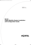
Base Station Wiring
The Base station is connected using an RJ11 connector, with twisted pair from a
Cat4 cable or similar, however the connection at the DMC is RJ45.
On a DMC080, two base stations can be connected from the RJ45 connection on
the DMC, and four base stations per RJ45 connector on the DMC320 (eight base
stations in total, having two RJ45 interfaces).
Use the following tables to determine which pairs to use for which base stations:
Please note that on the RJ11 interface, it is always Pins 2 and 3 that will be used
for the twisted pair. This is regardless of the base station numbering.
DMC080
RJ45 Connector
Base station
0
1
DMC320
RJ45 Connector 1
Base Station
0
1
2
3
RJ45 Connector 2
Base Station
0
1
2
3
12
Pins
4-5
1-2
Pins
4-5
1-2
3-6
7-8
Pins
4-5
1-2
3-6
7-8
NN40011-036 Issue 1.2 BCM Rls 6.0
Digital Mobility Configuration
Installing the Base Station
1. Use a twisted pair wire, e.g. Cat 4, between the DMC and the base station
with an RJ11 connector at the base station end of the wire. Connect the
wire to the plug using the two inner connectors of the plug. Pull the wire
through the wall bracket.
2. Mount the wall bracket on the wall using the screws accompanying the
base station. Do not fasten the screws completely to allow for adjustments
of the wire length when connecting the wire to the base station.
3. Connect the RJ11 plug to the rear of the base station. Adjust the length of
the wire, and then fasten the wall bracket.
4. Click the base station to the wall bracket.
Note: If you need to remove the base station, separate it from the wall bracket
with a gentle push of a screwdriver inserted between the wall bracket and the
base station.
NN40011-036 Issue 1.2 BCM Rls 6.0
13
Digital Mobility Configuration
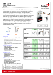
BCM DECT Cable Installations Utilizing Structured
Cabling
The DMC can be interfaced with the BCM via structured cabling. This could be
achieved by using combination of topology as outlined in the diagram below.
Installing Repeaters
Repeaters are wireless so relatively easy to install. They are used to extend the
radio coverage of a given base station, but do not have the ability to increase the
number of channels available from each base station. They support 2 channels
only, utilizing these from the four available of the base station they are assigned
to.
The repeater can only be registered on the system when placed within the
coverage area of a base station or within the coverage area of an alreadyinstalled repeater. Up to six repeaters can be used to extend radio coverage for a
base station.
Installing repeaters requires a software installation / programming as well as a
hardware installation.
1. Pull the power supply wire through the wall bracket, and mount the wall
bracket on the wall using the screws accompanying the repeater. Do not
14
NN40011-036 Issue 1.2 BCM Rls 6.0
Digital Mobility Configuration
fasten the screws completely to allow for adjustments of the wire length
when connecting the wire to the base station.
2. Connect the RJ11 plug to the rear of the repeater. Adjust the length of the
wire, and then fasten the wall bracket.
3. Click the base station to the wall bracket.
NN40011-036 Issue 1.2 BCM Rls 6.0
15
Digital Mobility Configuration
Installing External Antenna
The repeater can be fitted with an external antenna to increase the coverage
area further. The antenna points to an external position to create a remote cell up
to 1000 meters from the base station.
The external antenna used for the repeater is to be fixed-mounted on indoor
permanent structures providing a separation distance of at least 20 cm from all
persons during normal operation and must not be co-located or operating in
conjunction with any other antenna or transmitter.
The external antenna can be placed up to one meter from the repeater and must
be placed in the direction of the base station that the repeater should
synchronies with. If the external antenna and repeater is part of a repeater jump,
the antenna should be directed towards the repeater to be synchronised with.
The external antenna comes with a wall mounting holder into which the external
antenna can be clipped on to the main unit.
16
NN40011-036 Issue 1.2 BCM Rls 6.0
Digital Mobility Configuration
1. To connect the external antenna to the repeater, break off the tab covering
the antenna connection at the rear of the repeater.
2. Mount the wall bracket for the external antenna on the wall using the
accompanying 30mm screws.
3. Simply clip the Antenna into position on the wall mounting bracket and
connect the antenna cable at the rear of the repeater with the connection
plug at the bottom of the external antenna.
NN40011-036 Issue 1.2 BCM Rls 6.0
17
Digital Mobility Configuration
Programming a Repeater
With the base stations and repeaters installed, it will now be necessary to
program the repeaters to synchronise with their respective base stations.
A base station can have up to six repeaters programmed to it, increasing the
radio coverage. But each repeater must also be programmed with a Repeater
Number that will not interfere with the synchronisation and any adjoining
repeater.
The repeaters are configured using the Digital Mobility Service Tool. You will
need to install the Digital Mobility Service Tool application from the BCM to the
computer that is to be used to program the repeater.
The Digital Mobility Service Tool may be run on the following operating systems:
Windows XP Professional SP3
Windows Vista SP2 32 bit
Windows 7 Professional, Ultimate and Enterprise 32 bit
System Requirements:
Minimum 200Mhz (Intel/AMD)
Minimum 10 MB RAM recommended
1. Open Internet Explorer.In the address field type (replacing the relevant
part with your BCM IP address): http://<bcm ip address>/
2. Click on Go, or press Return on your keyboard.
18
NN40011-036 Issue 1.2 BCM Rls 6.0
Digital Mobility Configuration
Note: You can also use the Web Page button in Element Manager to launch a
web broswer session. The BCM you wish to access must be selected in the
Element Navigation Panel to do this.
3. If you are presented with the Certificate Error window, click on Continue
to this website (not recommended).
4. Accept any further security messages that you may get presented with.
NN40011-036 Issue 1.2 BCM Rls 6.0
19
Digital Mobility Configuration
5. You will now see the login screen, enter your BCM User name and
Password. By default these are set to User ID: nnadmin Password:
PlsChgMe! Click on OK.
6. In the Welcome to BCM window, ensure the Main tab has been selected,
and the BCM button clicked.
7. From the Applications list, select Other Administrator Applications and
click Run.
20
NN40011-036 Issue 1.2 BCM Rls 6.0
Digital Mobility Configuration
8. Again, accept any security messages that appear, and if prompted enter
any login details.
9. The Administrator Applications screen will be displayed.
10. The Administration Applications page will be displayed.
11. Then select the Digital Mobility Service Tool link.
NN40011-036 Issue 1.2 BCM Rls 6.0
21
Digital Mobility Configuration
12. Select the link to download the Service Tool and down load the software
to your computer.
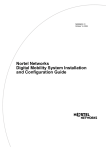
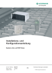
13. Once the application has been downloaded, you will need to connect the
computer to the repeater. This is done using the Service Tool.
Serial
Cable
Modular
Adapter
Serial
Connector
to COM
port
RJ11 4
pole port
RJ11 6
Pole Port
RJ11 6
Pole Port to
modular
adapter
Digital Mobility Service Tool
22
NN40011-036 Issue 1.2 BCM Rls 6.0
Digital Mobility Configuration
14. Unplug the power supply from the repeater and connect the modular
adapter to the repeater port. Connect the power supply to the adapters
RJ11 4pole port and the serial cable to the RJ11 6 pole port.
15. Attach the 9 pin serial connector to the computers COM port.
16. With the Service Tool attached to the repeater and computer, run the
installed application Digital Mobility Service Tool. This can be run from
the start menu for example:
NN40011-036 Issue 1.2 BCM Rls 6.0
23
Digital Mobility Configuration
17. Once opened the Connection settings screen will appear. Confirm the
COM port number attached to the „Serial Device‟. Select the required
repeater from the drop down list. In this example a „Repeater 25‟ has
been selected. Click the Proceed button.
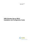
18. The programming window will now be launched. You will need to input the
ARI number of the DMC. This is found on the System label found on the
back of the DMC. You can also read the ARI code using the System
Information command under the Settings menu in the DMC OAM
program.
24
NN40011-036 Issue 1.2 BCM Rls 6.0
Digital Mobility Configuration
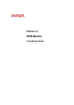
19. Next input the Base station that the repeater is to synchronize with, and
the repeater number (use the table 1 to determine the correct repeater
number).
ARI
Number
Note: When configuring numbers for Repeaters in a repeater jump, if you intend
to use more than three repeaters, then the number scheme would start again
after the third repeater in the jump.
In this example the repeaters are associated with the first base station 0
therefore the first repeater is repeater 64. After the third repeater 192, the
numbering process starts again for the fourth repeater, indicated as 64.
64
128
192
64
128
Table 1
Base Station
Repeater 1
Repeater 2
Repeater 3
0
1
2
3
4
5
6
7
64
65
66
67
68
69
70
71
128
129
130
131
132
133
134
135
192
193
194
195
196
197
198
199
NN40011-036 Issue 1.2 BCM Rls 6.0
25
Digital Mobility Configuration
8
9
10
11
12
13
14
15
72
73
74
75
76
77
78
79
136
137
138
139
140
141
142
143
200
201
202
203
204
205
206
207
20. For the Busy Bit field, leave the default setting to 2. Selecting the Debug
Bit check box is useful for error findings on the system. When selecting
the Debug Bit check box, the handset beeps when it logs on the repeater.
When the handset is off hook and connected to the repeater, you will hear
a beep every three seconds in the handset. In normal operation, this
should be left unchecked.
21. Click Write to confirm the settings and program the repeater. Then click
Read to check that the settings are as required.
22. The repeater has now been programmed.
The Digital Mobility Service Tool also allows the following aspects of the Digital
Mobility solution to be managed
Handset firmware upgrading
Handset audio-gain adjustment for noisy environments
Handset Microphone and loudspeaker gain adjustment
Use of this tool requires a programming cable and a handset programming
cradle. For Digital Mobility Handset 743x/744x and DECT Handset 413x/414x the
regular charging stand is used.
26
NN40011-036 Issue 1.2 BCM Rls 6.0
Digital Mobility Configuration
Configuring the Digital Mobility Controller (DMC)
Now that the base stations and repeaters have been assigned and programmed,
the Digital Mobility Controller can now be configured.
Power up the DMC by plugging the power supply cable into the front power point.
Connecting to the DMC
There are two methods of connecting to the DMC, these being a direct
connection with a null modem cable or the use of an IP to serial converter.
Note: It should be stated that the null modem cable should use 8 pins of the
required serial connection, so some of the null modem cables available may not
provide all of the necessary connections. Please refer to the Avaya
documentation for a detailed explanation of the pins being used.
Both of the suggested connection methods require connection to the COM port
on the DMC.
NN40011-036 Issue 1.2 BCM Rls 6.0
27
Digital Mobility Configuration
For IP to serial converter devices please refer to the documentation that is
included with the converter device itself.
Examples of possible IP to Serial Converter connections
Configuring the DMC
The DMC can be programmed using the Digital Mobility Controller OAM
(Operation, Administration and Maintenance) program. This is again downloaded
from the BCM. Using this interface, it is possible to configure the DMC on
following parameters that are useful when setting up the system.
Parameter
Change Password
Suppression Control
Action
When starting the DMC OAM program you will be prompted for a
password. The default password is: default. It is recommended to
change this password at the earliest opportunity.
If necessary, you can change the suppression level to make the
handsets function better in different noisy environments.
Subscription
The subscription setting must be set to Allow Subscription
before additional handsets can be subscribed to the system. This
allows the DMC to send out its ARI code so the handsets read
which system to log onto.
Cable Delay
Following the installation of the DMC and the base station, a
cable delay measurement must be taken in order to synchronize
the system.
The cable delay measurement will trigger the system to reboot
and all calls will be dropped.
28
NN40011-036 Issue 1.2 BCM Rls 6.0
Digital Mobility Configuration
Installing the Digital Mobility Controller OAM
Direct connection is completed through a null modem cable connected to the
RS232 port on the DMC and the serial port on the PC.
The Digital Mobility Controller may be run on the following operating systems:
Windows XP Professional SP3
Windows Vista SP2 32 bit
Windows 7 Professional, Ultimate and Enterprise 32 bit
System Requirements:
Minimum 200Mhz (Intel/AMD)
Minimum 10 MB RAM recommended
1. Open Internet Explorer.In the address field type (replacing the relevant
part with your BCM IP address): http://<bcm ip address>/
2. Click on Go, or press Return on your keyboard.
Note: You can also use the Web Page button in Element Manager to launch a
web broswer session. The BCM you wish to access must be selected in the
Element Navigation Panel to do this.
NN40011-036 Issue 1.2 BCM Rls 6.0
29
Digital Mobility Configuration
3. If you are presented with the Certificate Error window, click on Continue
to this website (not recommended).
4. Accept any further security messages that you may get presented with.
5. You will now see the login screen, enter your BCM User name and
Password. By default these are set to User ID: nnadmin Password:
PlsChgMe! Click on OK.
30
NN40011-036 Issue 1.2 BCM Rls 6.0
Digital Mobility Configuration
6. In the Welcome to BCM window, ensure the Main tab has been selected,
and the BCM button clicked.
7. From the Applications list, select Other Administrator Applications and
click Run.
8. Again, accept any security messages that appear, and if prompted enter
any login details.
9. The Administrator Applications screen will be displayed.
NN40011-036 Issue 1.2 BCM Rls 6.0
31
Digital Mobility Configuration
10. The Administration Applications page will be displayed.
11. Then select the Digital Mobility Controller link.
32
NN40011-036 Issue 1.2 BCM Rls 6.0
Digital Mobility Configuration
12. Select the link to download the Digital Mobility Controller and download
the software to you computer.
13. Once installed, run the installed application Digital Mobility Controller.
This can be run from the start menu for example:
NN40011-036 Issue 1.2 BCM Rls 6.0
33
Digital Mobility Configuration
14. The Connection dialogue box will appear. For the Serial device, select the
COM Port number that the DMC is connected to on your computer and
click OK. If you wish to change the communications settings click on the
Change Communications Configuration button.
15. The Digital Mobility Controller OAM will be launched, presenting you with
a Password dialogue box. Type the password “default” and select OK.
34
NN40011-036 Issue 1.2 BCM Rls 6.0
Digital Mobility Configuration
16. The DMC screen will show a grid for each of the handsets dependant on
whether you are configuring a DMC080 or a DMC320 as to the number of
TCM loops available for handsets.
17. Select the command Settings and click Measure Cable Delay from the
drop down menu. This will allow you to synchronize the base stations
connected to the DMC.
18. On the next screen click Measure. A warning will appear asking you to
confirm the measurement. Click OK.
NN40011-036 Issue 1.2 BCM Rls 6.0
35
Digital Mobility Configuration
19. Another dialogue box will appear saying that the measuring could take up
to 10 minutes to complete. Leave this to run and eventually the Password
dialogue box will appear again.
20. Type the password „default‟ and then click „Read‟. The base stations will
now be displayed with a number of ticks against the measurement of their
distance to the DMC.
36
NN40011-036 Issue 1.2 BCM Rls 6.0
Digital Mobility Configuration
21. The base stations are now synchronised with the DMC and ready for use.
Registering Handsets
This section provides you with information about handset registration and
subscription. You must register and subscribe a handset before you can use it.
The section also contains information about host system features and host
system and handset interoperability.
When registering handsets you enter information about the handset settings
(such as; the handset serial number, name, directory number etc.) in the system
database. When subscribing handsets you subscribe a registered handset to the
system for usage. If the handset is not registered in the system database,
subscription of the handset is not possible.
When a connection between a DMC and the system is established, the DMC
OAM program displays all the information for registering handsets.
Finding the IPEI number of a Handset
The IPEI (International Portable Equipment Identity) number of the handset is
required to register it using the DMC OAM. There are two methods available for
finding the IPEI.
NN40011-036 Issue 1.2 BCM Rls 6.0
37
Digital Mobility Configuration
1. If the Handset battery has not yet been charged, then remove the back
cover and battery to view the Serial Number (first 12 digits)
2. With the battery fully charged and handset powered on, press *99984*
the handset will display the IPEI number on the second line of the display.
With the IPEI Number now available, the handsets can be registered with the
DMC.
38
NN40011-036 Issue 1.2 BCM Rls 6.0
Digital Mobility Configuration
Registering a Handset using the DMC OAM
If you have closed the DMC OAM interface, then follow steps 5 to 8 of the
previous section.
1. Highlight and right click on a line next to a TCM number and select
“Create”.
Right Click
2. In the IPEI Field type the number recorded for the handset you wish to
register. Select if this is to be a Master handset or not (with special
privileges).
3. In the AC field, type the authentication code (optional). The authentication
code is a subscription password of a maximum eight digits that can be
used when subscribing the handset to the DMC (this may be left blank
depending on the customer‟s requirements). Simply click on create.
NN40011-036 Issue 1.2 BCM Rls 6.0
39
Digital Mobility Configuration
4. The handsets will be seen on each line as you register them.
5. Once all of the handsets have been registered, click on the button “Read
All”. This will update the handsets in relation to their physical connection
to the BCM, including their DN number.
6. The handsets are now registered, but will need to be subscribed.
40
NN40011-036 Issue 1.2 BCM Rls 6.0
Digital Mobility Configuration
Subscribing Handsets
On the Digital Mobility Handsets perform the following sequence:
1. Press MENU key.
2. Press the Left arrow (<) key twice to display “MENU LOGIN”. Press OK
().
3. Press the Left arrow (<) key twice to display “SUBSCRIPTION CREATE”.
Press OK ().
4. “SUBSCRIPTION SEARCH ID:” appears displaying the DMC number.
Press OK ().
5. “CREATE SYSTEM 01 AC:” appears. Enter an AC as required (based on
whether an Authentication Code was created during the registration
process), then press OK ().
The handset will now display the DN assigned to it and is operational.
Registering a Master Handset using the Handset
When powering up the DMC, the system automatically enters into subscription
mode for 10 minutes. This is the time that is available to subscribe the first
handset which automatically becomes the Master handset.
Note: Registration of the first handset - the Master handset automatically when subscribing the handset to the system.
is done
1. Power up the handset.
2. Press MENU key.
3. Press Left arrow key twice to go to “MENU LOGIN”.
4. Press OK ().
5. Press Left arrow key twice to display “SUBSCRIPTION CREATE”. Press
OK (). The handset will now search for the serial number of the system.
6. As soon as the right serial number of the system appears in the display
press OK (). (The serial number is indicated on the label on the rear of
the DMC).
NN40011-036 Issue 1.2 BCM Rls 6.0
41
Digital Mobility Configuration
7. “CREATE SYSTEM 01 AC:” appears. Enter an AC as required (based on
whether an Authentication Code was created during the registration
process), then press OK ()
An antenna symbol will appear in the display to indicate a successful
subscription.
The handset has now become the Master handset for the system and will be
placed on TCM loop no. 1.
Note: It is possible to have more than one Master handset. Registration and
subscription of additional Master handsets through a Master handset follows the
same procedure as for registering additional handsets and subscribing handsets
which is described in the next section. This means that an additional Master
handset is not registered automatically when subscribing it to the system.
Registering Additional Handsets
1. Press MENU and the arrow keys to go to “EXT. SERVICE”.
2. Press OK () to enter the next level of options. Using the arrow keys go to
“CONFIG. USER”.
3. Press OK ().Using the arrow keys go to “ADD”.
4. Press OK ().Using the arrow keys go to “ENTER POS.”
5. Press OK ().Using the arrow keys enter the position of additional
handsets.
6. Press OK (). “IPEI” appears in the display. Type the serial number of the
handset. The IPEI serial number is found on the label behind the battery
pack.
7. Press OK (). “AC” appears in the display. Type an authentication code
(max. eight digits) (AC is optional).
8. Press OK (). “SPEC. RIGHTS” appears in the display. Special rights are
only given to additional Master handsets. Select No SPEC. RIGHTS.
9. Press OK (). Select “PRIMA” or “SECOND”. Secondary is only an option
if the handset is being registered on a linked system. In a linked system
there is a Primary DMC and a Secondary DMC.
42
NN40011-036 Issue 1.2 BCM Rls 6.0
Digital Mobility Configuration
10. Press OK (). “TCM LOOP” appears in the display. Type the TCM loop
number of the chosen Primary or Secondary DMC, and then press OK
(). A Successful message appears in the display.
11. To register another handset, press OK () and repeat steps 2 to 10.
12. Press the MENU key to exit.
13. Once registered, the handsets will still need to be subscribed to the
system. Please refer to the Subscribing Handsets section of this guide.
NN40011-036 Issue 1.2 BCM Rls 6.0
43
Digital Mobility Configuration
Avaya Documentation Links
44
Digital Mobility System Installation and Configuration Guide
Digital Mobility Phone 413X and 414X User Guide
Digital Mobility Phone 4145Ex and 4146Ex User Guide
Digital Mobility Phone 7420 User Guide
Digital Mobility Phone 743X/744X User Guide
NN40011-036 Issue 1.2 BCM Rls 6.0