1
Configuring GRE, NAT,
RIPSO, and BFE Services
BayRS Version 13.20
Site Manager Software Version 7.20
BCC Version 4.20
Part No. 305753-A Rev 00
April 1999
Bay Networks, Inc.
4401 Great America Parkway
Santa Clara, CA 95054
Copyright © 1999 Bay Networks, Inc.
All rights reserved. Printed in the USA. April 1999.
The information in this document is subject to change without notice. The statements, configurations, technical data,
and recommendations in this document are believed to be accurate and reliable, but are presented without express or
implied warranty. Users must take full responsibility for their applications of any products specified in this document.
The information in this document is proprietary to Bay Networks, Inc.
The software described in this document is furnished under a license agreement and may only be used in accordance
with the terms of that license. A summary of the Software License is included in this document.
Trademarks
Bay Networks is a registered trademark and ASN, BayRS, BayStack, and BCC are trademarks of Bay Networks, Inc.
All other trademarks and registered trademarks are the property of their respective owners.
Restricted Rights Legend
Use, duplication, or disclosure by the United States Government is subject to restrictions as set forth in subparagraph
(c)(1)(ii) of the Rights in Technical Data and Computer Software clause at DFARS 252.227-7013.
Notwithstanding any other license agreement that may pertain to, or accompany the delivery of, this computer
software, the rights of the United States Government regarding its use, reproduction, and disclosure are as set forth in
the Commercial Computer Software-Restricted Rights clause at FAR 52.227-19.
Statement of Conditions
In the interest of improving internal design, operational function, and/or reliability, Bay Networks, Inc. reserves the
right to make changes to the products described in this document without notice.
Bay Networks, Inc. does not assume any liability that may occur due to the use or application of the product(s) or
circuit layout(s) described herein.
Portions of the code in this software product may be Copyright © 1988, Regents of the University of California. All
rights reserved. Redistribution and use in source and binary forms of such portions are permitted, provided that the
above copyright notice and this paragraph are duplicated in all such forms and that any documentation, advertising
materials, and other materials related to such distribution and use acknowledge that such portions of the software were
developed by the University of California, Berkeley. The name of the University may not be used to endorse or
promote products derived from such portions of the software without specific prior written permission.
SUCH PORTIONS OF THE SOFTWARE ARE PROVIDED “AS IS” AND WITHOUT ANY EXPRESS OR
IMPLIED WARRANTIES, INCLUDING, WITHOUT LIMITATION, THE IMPLIED WARRANTIES OF
MERCHANTABILITY AND FITNESS FOR A PARTICULAR PURPOSE.
In addition, the program and information contained herein are licensed only pursuant to a license agreement that
contains restrictions on use and disclosure (that may incorporate by reference certain limitations and notices imposed
by third parties).
ii
305753-A Rev 00
Bay Networks, Inc. Software License Agreement
NOTICE: Please carefully read this license agreement before copying or using the accompanying software or
installing the hardware unit with pre-enabled software (each of which is referred to as “Software” in this Agreement).
BY COPYING OR USING THE SOFTWARE, YOU ACCEPT ALL OF THE TERMS AND CONDITIONS OF
THIS LICENSE AGREEMENT. THE TERMS EXPRESSED IN THIS AGREEMENT ARE THE ONLY TERMS
UNDER WHICH BAY NETWORKS WILL PERMIT YOU TO USE THE SOFTWARE. If you do not accept these
terms and conditions, return the product, unused and in the original shipping container, within 30 days of purchase to
obtain a credit for the full purchase price.
1. License Grant. Bay Networks, Inc. (“Bay Networks”) grants the end user of the Software (“Licensee”) a personal,
nonexclusive, nontransferable license: a) to use the Software either on a single computer or, if applicable, on a single
authorized device identified by host ID, for which it was originally acquired; b) to copy the Software solely for backup
purposes in support of authorized use of the Software; and c) to use and copy the associated user manual solely in
support of authorized use of the Software by Licensee. This license applies to the Software only and does not extend
to Bay Networks Agent software or other Bay Networks software products. Bay Networks Agent software or other
Bay Networks software products are licensed for use under the terms of the applicable Bay Networks, Inc. Software
License Agreement that accompanies such software and upon payment by the end user of the applicable license fees
for such software.
2. Restrictions on use; reservation of rights. The Software and user manuals are protected under copyright laws.
Bay Networks and/or its licensors retain all title and ownership in both the Software and user manuals, including any
revisions made by Bay Networks or its licensors. The copyright notice must be reproduced and included with any
copy of any portion of the Software or user manuals. Licensee may not modify, translate, decompile, disassemble, use
for any competitive analysis, reverse engineer, distribute, or create derivative works from the Software or user manuals
or any copy, in whole or in part. Except as expressly provided in this Agreement, Licensee may not copy or transfer
the Software or user manuals, in whole or in part. The Software and user manuals embody Bay Networks’ and its
licensors’ confidential and proprietary intellectual property. Licensee shall not sublicense, assign, or otherwise
disclose to any third party the Software, or any information about the operation, design, performance, or
implementation of the Software and user manuals that is confidential to Bay Networks and its licensors; however,
Licensee may grant permission to its consultants, subcontractors, and agents to use the Software at Licensee’s facility,
provided they have agreed to use the Software only in accordance with the terms of this license.
3. Limited warranty. Bay Networks warrants each item of Software, as delivered by Bay Networks and properly
installed and operated on Bay Networks hardware or other equipment it is originally licensed for, to function
substantially as described in its accompanying user manual during its warranty period, which begins on the date
Software is first shipped to Licensee. If any item of Software fails to so function during its warranty period, as the sole
remedy Bay Networks will at its discretion provide a suitable fix, patch, or workaround for the problem that may be
included in a future Software release. Bay Networks further warrants to Licensee that the media on which the
Software is provided will be free from defects in materials and workmanship under normal use for a period of 90 days
from the date Software is first shipped to Licensee. Bay Networks will replace defective media at no charge if it is
returned to Bay Networks during the warranty period along with proof of the date of shipment. This warranty does not
apply if the media has been damaged as a result of accident, misuse, or abuse. The Licensee assumes all responsibility
for selection of the Software to achieve Licensee’s intended results and for the installation, use, and results obtained
from the Software. Bay Networks does not warrant a) that the functions contained in the software will meet the
Licensee’s requirements, b) that the Software will operate in the hardware or software combinations that the Licensee
may select, c) that the operation of the Software will be uninterrupted or error free, or d) that all defects in the
operation of the Software will be corrected. Bay Networks is not obligated to remedy any Software defect that cannot
be reproduced with the latest Software release. These warranties do not apply to the Software if it has been (i) altered,
except by Bay Networks or in accordance with its instructions; (ii) used in conjunction with another vendor’s product,
resulting in the defect; or (iii) damaged by improper environment, abuse, misuse, accident, or negligence. THE
FOREGOING WARRANTIES AND LIMITATIONS ARE EXCLUSIVE REMEDIES AND ARE IN LIEU OF ALL
OTHER WARRANTIES EXPRESS OR IMPLIED, INCLUDING WITHOUT LIMITATION ANY WARRANTY OF
MERCHANTABILITY OR FITNESS FOR A PARTICULAR PURPOSE. Licensee is responsible for the security of
305753-A Rev 00
iii
its own data and information and for maintaining adequate procedures apart from the Software to reconstruct lost or
altered files, data, or programs.
4. Limitation of liability. IN NO EVENT WILL BAY NETWORKS OR ITS LICENSORS BE LIABLE FOR ANY
COST OF SUBSTITUTE PROCUREMENT; SPECIAL, INDIRECT, INCIDENTAL, OR CONSEQUENTIAL
DAMAGES; OR ANY DAMAGES RESULTING FROM INACCURATE OR LOST DATA OR LOSS OF USE OR
PROFITS ARISING OUT OF OR IN CONNECTION WITH THE PERFORMANCE OF THE SOFTWARE, EVEN
IF BAY NETWORKS HAS BEEN ADVISED OF THE POSSIBILITY OF SUCH DAMAGES. IN NO EVENT
SHALL THE LIABILITY OF BAY NETWORKS RELATING TO THE SOFTWARE OR THIS AGREEMENT
EXCEED THE PRICE PAID TO BAY NETWORKS FOR THE SOFTWARE LICENSE.
5. Government Licensees. This provision applies to all Software and documentation acquired directly or indirectly by
or on behalf of the United States Government. The Software and documentation are commercial products, licensed on
the open market at market prices, and were developed entirely at private expense and without the use of any U.S.
Government funds. The license to the U.S. Government is granted only with restricted rights, and use, duplication, or
disclosure by the U.S. Government is subject to the restrictions set forth in subparagraph (c)(1) of the Commercial
Computer Software––Restricted Rights clause of FAR 52.227-19 and the limitations set out in this license for civilian
agencies, and subparagraph (c)(1)(ii) of the Rights in Technical Data and Computer Software clause of DFARS
252.227-7013, for agencies of the Department of Defense or their successors, whichever is applicable.
6. Use of Software in the European Community. This provision applies to all Software acquired for use within the
European Community. If Licensee uses the Software within a country in the European Community, the Software
Directive enacted by the Council of European Communities Directive dated 14 May, 1991, will apply to the
examination of the Software to facilitate interoperability. Licensee agrees to notify Bay Networks of any such
intended examination of the Software and may procure support and assistance from Bay Networks.
7. Term and termination. This license is effective until terminated; however, all of the restrictions with respect to
Bay Networks’ copyright in the Software and user manuals will cease being effective at the date of expiration of the
Bay Networks copyright; those restrictions relating to use and disclosure of Bay Networks’ confidential information
shall continue in effect. Licensee may terminate this license at any time. The license will automatically terminate if
Licensee fails to comply with any of the terms and conditions of the license. Upon termination for any reason,
Licensee will immediately destroy or return to Bay Networks the Software, user manuals, and all copies. Bay
Networks is not liable to Licensee for damages in any form solely by reason of the termination of this license.
8. Export and Re-export. Licensee agrees not to export, directly or indirectly, the Software or related technical data
or information without first obtaining any required export licenses or other governmental approvals. Without limiting
the foregoing, Licensee, on behalf of itself and its subsidiaries and affiliates, agrees that it will not, without first
obtaining all export licenses and approvals required by the U.S. Government: (i) export, re-export, transfer, or divert
any such Software or technical data, or any direct product thereof, to any country to which such exports or re-exports
are restricted or embargoed under United States export control laws and regulations, or to any national or resident of
such restricted or embargoed countries; or (ii) provide the Software or related technical data or information to any
military end user or for any military end use, including the design, development, or production of any chemical,
nuclear, or biological weapons.
9. General. If any provision of this Agreement is held to be invalid or unenforceable by a court of competent
jurisdiction, the remainder of the provisions of this Agreement shall remain in full force and effect. This Agreement
will be governed by the laws of the state of California.
Should you have any questions concerning this Agreement, contact Bay Networks, Inc., 4401 Great America Parkway,
P.O. Box 58185, Santa Clara, California 95054-8185.
LICENSEE ACKNOWLEDGES THAT LICENSEE HAS READ THIS AGREEMENT, UNDERSTANDS IT, AND
AGREES TO BE BOUND BY ITS TERMS AND CONDITIONS. LICENSEE FURTHER AGREES THAT THIS
AGREEMENT IS THE ENTIRE AND EXCLUSIVE AGREEMENT BETWEEN BAY NETWORKS AND
LICENSEE, WHICH SUPERSEDES ALL PRIOR ORAL AND WRITTEN AGREEMENTS AND
COMMUNICATIONS BETWEEN THE PARTIES PERTAINING TO THE SUBJECT MATTER OF THIS
AGREEMENT. NO DIFFERENT OR ADDITIONAL TERMS WILL BE ENFORCEABLE AGAINST BAY
NETWORKS UNLESS BAY NETWORKS GIVES ITS EXPRESS WRITTEN CONSENT, INCLUDING AN
EXPRESS WAIVER OF THE TERMS OF THIS AGREEMENT.
iv
305753-A Rev 00
Contents
Preface
Before You Begin ............................................................................................................. xv
Text Conventions .............................................................................................................xvi
Acronyms ........................................................................................................................xvii
Related Publications ...................................................................................................... xviii
How to Get Help ..............................................................................................................xix
Chapter 1
Introduction
Generic Routing Encapsulation (GRE) ...........................................................................1-1
Network Address Translation (NAT) ................................................................................1-2
Revised IP Security Option (RIPSO) ..............................................................................1-3
Blacker Front End (BFE) .................................................................................................1-4
Chapter 2
Configuring GRE Tunnels
How GRE Tunneling Works ............................................................................................2-2
Avoiding IP Tunnel Misconfiguration ...............................................................................2-5
Announce Policies ....................................................................................................2-5
Accept Policies .........................................................................................................2-6
Static Routes ............................................................................................................2-6
Creating a Generic Routing Encapsulation Tunnel .........................................................2-7
Adding a GRE Tunnel ...............................................................................................2-7
Enabling or Disabling a GRE Tunnel ........................................................................2-9
Deleting a GRE Tunnel ...........................................................................................2-10
Adding and Deleting Protocols for GRE Tunnels ..........................................................2-11
Adding a Protocol to a GRE Tunnel .......................................................................2-11
Adding an IP Protocol Interface .......................................................................2-11
Adding an IPX Protocol Interface .....................................................................2-12
305753-A Rev 00
v
Enabling or Disabling a Protocol ............................................................................2-13
Deleting a Protocol from a GRE Tunnel .................................................................2-14
Configuring a Remote Tunnel End Point .......................................................................2-15
Adding a Remote Tunnel End Point .......................................................................2-15
Step 1. Configuring a Remote Physical End Point ...........................................2-15
Step 2. Configuring a Remote Logical Interface ..............................................2-16
Enabling or Disabling a Remote Tunnel End Point .................................................2-18
Deleting a Remote Tunnel End Point .....................................................................2-19
Chapter 3
Configuring Network Address Translation
NAT Concepts and Terminology .....................................................................................3-2
How NAT Works .......................................................................................................3-3
NAT Address Translation Options .............................................................................3-8
Dynamic Address Translation ............................................................................3-8
Static Address Translation .................................................................................3-9
N-to-1 Translation ..............................................................................................3-9
NAT Synchronization ................................................................................................3-9
Starting NAT Services ..................................................................................................3-11
Using the BCC .......................................................................................................3-11
Adding NAT to the Router ................................................................................3-11
Specifying a Local Address Range for NAT Translation ...................................3-11
Specifying a Global Address Range for NAT Translation .................................3-12
Configuring a Local NAT Interface ...................................................................3-12
Configuring a Global NAT Interface .................................................................3-13
Configuration Example ....................................................................................3-13
Using Site Manager ................................................................................................3-14
Starting NAT on the Router and Specifying the Local Interface .......................3-14
Configuring the Global Interface ......................................................................3-15
Configuring a Local and Global Address Range .............................................3-16
Where to Go Next ..................................................................................................3-17
Starting NAT Synchronization .......................................................................................3-18
Using the BCC .......................................................................................................3-19
Enabling NAT Synchronization ........................................................................3-19
Adding NAT Synchronization Peers .................................................................3-19
Configuration Example ....................................................................................3-20
vi
305753-A Rev 00
Using Site Manager ................................................................................................3-20
Enabling NAT Synchronization ........................................................................3-20
Adding NAT Synchronization Peers .................................................................3-21
Customizing NAT Global Parameters ...........................................................................3-22
Enabling and Disabling NAT on the Router ............................................................3-23
Configuring the Soloist Slot Mask ..........................................................................3-24
Logging NAT Messages .........................................................................................3-26
Enabling and Disabling Translation Entry Timeout .................................................3-28
Configuring the Translation Entry Timeout Value ...................................................3-29
Customizing a NAT Interface ........................................................................................3-31
Adding NAT to an IP Interface ................................................................................3-31
Enabling and Disabling NAT on an Interface ..........................................................3-33
Modifying the Interface Type ..................................................................................3-35
Deleting NAT from an IP Interface ..........................................................................3-37
Configuring Static Address Translation .........................................................................3-38
Adding a Static Address Mapping ..........................................................................3-38
Enabling and Disabling a Static Address Mapping .................................................3-40
Deleting a Static Address Mapping ........................................................................3-41
Configuring Dynamic Local Address Ranges ...............................................................3-43
Adding a Local Address Range ..............................................................................3-43
Enabling and Disabling a Local Address Range ....................................................3-45
Deleting a Local Address Range ............................................................................3-47
Configuring Dynamic Global Address Ranges .............................................................3-48
Adding a Global Address Range ............................................................................3-48
Enabling and Disabling a Global Address Range ..................................................3-50
Deleting a Global Address Range ..........................................................................3-52
Configuring Network Address Port (N-to-1) Translation ................................................3-53
Customizing NAT Synchronization Parameters ............................................................3-58
Enabling and Disabling NAT Synchronization ........................................................3-58
Setting the Synchronized Router ID .......................................................................3-60
Setting the Synchronization Port ............................................................................3-62
Customizing Keepalive Parameters .......................................................................3-63
Configuring NAT Synchronization Peers .......................................................................3-65
Adding NAT Synchronization Peers .......................................................................3-65
305753-A Rev 00
vii
Enabling and Disabling NAT Synchronization Peers ..............................................3-67
Deleting NAT Synchronization Peers .....................................................................3-69
Chapter 4
Configuring RIPSO on an IP Interface
Security Label Format ....................................................................................................4-2
Inbound IP Datagrams ....................................................................................................4-4
Forwarded IP Datagrams ................................................................................................4-4
Originated IP Datagrams ................................................................................................4-5
Unlabeled IP Datagrams ................................................................................................4-5
Enabling and Disabling RIPSO .......................................................................................4-6
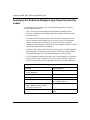
Specifying the IP Datagram Type for Stripping Security Options ....................................4-7
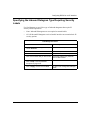
Specifying the Outbound Datagram Type Requiring Security Labels .............................4-8
Specifying the Inbound Datagram Type Requiring Security Labels ................................4-9
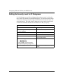
Setting the Security Level for IP Datagrams .................................................................4-10
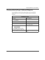
Choosing Authority Flags in Outbound Datagrams ......................................................4-11
Choosing Authority Flags in Inbound Datagrams .........................................................4-12
Supplying Implicit Labels for Unlabeled Inbound Datagrams .......................................4-13
Enabling and Disabling Default Labels for Unlabeled Outbound Datagrams ................4-14
Enabling and Disabling Error Labels for Outbound ICMP Error Datagrams .................4-15
RIPSO Example ...........................................................................................................4-16
Chapter 5
Connecting the Router to a Blacker Front End
BFE Addressing ..............................................................................................................5-2
Configuring Blacker Front-End Support ..........................................................................5-3
Appendix A
Site Manager Parameters
GRE Parameters ........................................................................................................... A-2
GRE Tunnel Parameters ......................................................................................... A-2
Remote Connection Parameters ............................................................................. A-4
NAT Parameters ............................................................................................................. A-7
NAT Global Parameters ........................................................................................... A-7
NAT Interface Parameters ..................................................................................... A-12
NAT Static Translation Parameters ........................................................................ A-14
NAT Dynamic Translation Local Address Range Parameters ............................... A-17
viii
305753-A Rev 00
NAT Dynamic Translation Global Address Range Parameters .............................. A-19
NAT Synchronization Peer Parameters ................................................................. A-21
RIPSO Parameters ...................................................................................................... A-24
Index
305753-A Rev 00
ix
Figures
Figure 2-1.
Simple GRE Tunnel Components ............................................................ 2-2
Figure 2-2.
GRE Tunnel Encapsulating the IP Protocol ............................................. 2-4
Figure 3-1.
Network Address Translation Example .................................................... 3-4
Figure 3-2.
NAT Detects the Source Address ............................................................ 3-5
Figure 3-3.
NAT Updates the Local/Global Translation Entry List .............................. 3-6
Figure 3-4.
NAT Replaces the Local Address with a Registered Source Address .... 3-7
Figure 3-5.
NAT Routers in a Synchronized Configuration ...................................... 3-10
Figure 3-6.
N-to-1 Translation (Local to Global) ....................................................... 3-53
Figure 3-7.
N-to-1 Translation (Global to Local) ....................................................... 3-55
Figure 4-1.
RIPSO Security Label ............................................................................. 4-2
Figure 4-2.
RIPSO Example .................................................................................... 4-17
Figure 5-1.
Blacker Front-End Network Configuration ............................................... 5-1
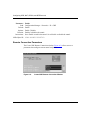
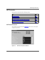
Figure A-1.
GRE Create Tunnels List Window ........................................................... A-2
Figure A-2.
Create GRE Remote Connection Window .............................................. A-4
Figure A-3.
NAT Base Group Record Window ........................................................... A-7
Figure A-4.
NAT Interface List Window .................................................................... A-12
Figure A-5.
NAT Static Translation List Window ....................................................... A-14
Figure A-6.
NAT Local Address Range List Window ................................................ A-17
Figure A-7.
NAT Global Address Range List Window .............................................. A-19
Figure A-8.
NAT Synchronization Peer List Window ................................................ A-21
Figure A-9.
IP Interface List Window ........................................................................ A-24
305753-A Rev 00
xi
Tables
Table 3-1.
NAT Log Message Types ......................................................................3-26
Table 5-1.
BFE X.25 Packet-Level Parameter Settings ............................................5-4
Table 5-2.
BFE X.25 Network Service Record Parameter Settings ..........................5-6
305753-A Rev 00
xiii
Preface
This guide describes the following services and what you do to start and
customize them on a Bay Networks® router:
•
Generic Routing Encapsulation (GRE) tunnels
•
Network Address Translation (NAT)
•
Basic Revised IP Security Option (RIPSO) security labels
•
Blacker front-end device connections
You can use Site Manager to configure any of these services on a router. You can
also use the Bay Command Console (BCC™) to configure GRE and NAT. In this
guide, you will find instructions for using both the BCC and Site Manager.
For instructions on how to start and use the BCC, see Using the Bay Command
Console (BCC); for instructions on how to start and use Site Manager, see
Configuring and Managing Routers with Site Manager.
Before You Begin
Before using this guide, you must complete the following procedures. For a new
router:
•
Install the router (see the installation guide that came with your router).
•
Connect the router to the network and create a pilot configuration file (see
Quick-Starting Routers, Configuring BayStack Remote Access, or Connecting
ASN Routers to a Network).
Make sure that you are running the latest version of Bay Networks BayRS™ and
Site Manager software. For information about upgrading BayRS and Site
Manager, see the upgrading guide for your version of BayRS.
305753-A Rev 00
xv
Configuring GRE, NAT, RIPSO, and BFE Services
Text Conventions
This guide uses the following text conventions:
angle brackets (< >)
Indicate that you choose the text to enter based on the
description inside the brackets. Do not type the
brackets when entering the command.
Example: If the command syntax is:
ping <ip_address>, you enter:
ping 192.32.10.12
bold text
Indicates command names and options and text that
you need to enter.
Example: Enter show ip {alerts | routes}.
Example: Use the dinfo command.
braces ({})
Indicate required elements in syntax descriptions
where there is more than one option. You must choose
only one of the options. Do not type the braces when
entering the command.
Example: If the command syntax is:
show ip {alerts | routes}, you must enter either:
show ip alerts or show ip routes, but not both.
brackets ([ ])
Indicate optional elements in syntax descriptions. Do
not type the brackets when entering the command.
Example: If the command syntax is:
show ip interfaces [-alerts], you can enter either:
show ip interfaces or show ip interfaces -alerts.
ellipsis points (. . . )
Indicate that you repeat the last element of the
command as needed.
Example: If the command syntax is:
ethernet/2/1 [<parameter> <value>] . . . , you enter
ethernet/2/1 and as many parameter-value pairs as
needed.
xvi
305753-A Rev 00
Preface
italic text
Indicates file and directory names, new terms, book
titles, and variables in command syntax descriptions.
Where a variable is two or more words, the words are
connected by an underscore.
Example: If the command syntax is:
show at <valid_route>
valid_route is one variable and you substitute one value
for it.
screen text
Indicates system output, for example, prompts and
system messages.
Example: Set Bay Networks Trap Monitor Filters
separator ( > )
Shows menu paths.
Example: Protocols > IP identifies the IP option on the
Protocols menu.
vertical line ( | )
Separates choices for command keywords and
arguments. Enter only one of the choices. Do not type
the vertical line when entering the command.
Example: If the command syntax is:
show ip {alerts | routes}, you enter either:
show ip alerts or show ip routes, but not both.
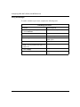
Acronyms
This guide uses the following acronyms:
305753-A Rev 00
ACC
access control center
BFE
Blacker front end
BGP
Border Gateway Protocol
DCE
data communication equipment
GRE
Generic Routing Encapsulation
ICMP
Internet Control Message Protocol
IP
Internet Protocol
xvii
Configuring GRE, NAT, RIPSO, and BFE Services
IPX
Internetwork Packet Exchange
ITU-T
International Telecommunication
Union-Telecommunication Standardization Sector
(formerly CCITT)
KDC
key distribution center
MAC
media access control
NAT
Network Address Translation
OSPF
Open Shortest Path First
RIP
Routing Information Protocol
RIPSO
Revised IP Security Option
TCP
Transmission Control Protocol
UDP
User Datagram Protocol
VPN
virtual private network
WAN
wide area network
Related Publications
For more information about GRE, NAT, and other IP services, refer to the
following publications:
•
BCC show Commands for IP Services (Bay Networks part number 305755-A
Rev 00)
Provides descriptions of all show commands for IP services, including the
commands that display GRE and NAT configuration and statistical data.
•
Configuring IP, ARP, RIP, and OSPF Services (Bay Networks part number
117356-E Rev 00)
Provides a description of IP, ARP, RIP, and OSPF services and instructions for
configuring them.
•
Configuring IP Exterior Gateway Protocols (BGP and EGP) (Bay Networks
part number 305752-A Rev 00)
Provides a description of Border Gateway Protocol (BGP) and Exterior
Gateway Protocol (EGP) services and instructions for configuring them.
xviii
305753-A Rev 00
Preface
You can now print Bay Networks technical manuals and release notes free,
directly from the Internet. Go to support.baynetworks.com/library/tpubs/. Find the
Bay Networks product for which you need documentation. Then locate the
specific category and model or version for your hardware or software product.
Using Adobe Acrobat Reader, you can open the manuals and release notes, search
for the sections you need, and print them on most standard printers. You can
download Acrobat Reader free from the Adobe Systems Web site,
www.adobe.com.
You can purchase Bay Networks documentation sets, CDs, and selected technical
publications through the Bay Networks Collateral Catalog. The catalog is located
on the World Wide Web at support.baynetworks.com/catalog.html and is divided
into sections arranged alphabetically:
•
The “CD ROMs” section lists available CDs.
•
The “Guides/Books” section lists books on technical topics.
•
The “Technical Manuals” section lists available printed documentation sets.
Make a note of the part numbers and prices of the items that you want to order.
Use the “Marketing Collateral Catalog description” link to place an order and to
print the order form.
How to Get Help
If you purchased a service contract for your Bay Networks product from a
distributor or authorized reseller, contact the technical support staff for that
distributor or reseller for assistance.
If you purchased a Bay Networks service program, contact one of the following
Bay Networks Technical Solutions Centers:
305753-A Rev 00
Technical Solutions Center
Telephone Number
Billerica, MA
800-2LANWAN (800-252-6926)
Santa Clara, CA
800-2LANWAN (800-252-6926)
Valbonne, France
33-4-92-96-69-68
Sydney, Australia
61-2-9927-8800
Tokyo, Japan
81-3-5402-7041
xix
Chapter 1
Introduction
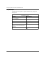
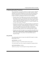
The following topics introduce concepts and terminology used in this guide:
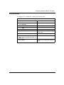
Topic
Page
Generic Routing Encapsulation (GRE)
1-1
Network Address Translation (NAT)
1-2
Revised IP Security Option (RIPSO)
1-3
Blacker Front End (BFE)
1-4
Generic Routing Encapsulation (GRE)
Generic Routing Encapsulation (GRE) is a protocol that allows transport of
non-IP traffic through IP-based systems. GRE, which is defined in RFCs 1701 and
1702, encapsulates Internet Protocol (IP) and other layer 3 protocols to enable
data transmission through an IP tunnel. This tunneling mechanism allows:
305753-A Rev 00
•
Transport of non-IP traffic through intermediate systems that support only IP
•
Creation of a virtual private network (VPN) that uses the Internet as a section
of your own private network
•
Communication between subnetworks with unregistered or discontiguous
network addresses
1-1
Configuring GRE, NAT, RIPSO, and BFE Services
A tunnel is a virtual point-to-point connection. It has as its end points the IP
addresses of two router IP interfaces, one serving as the source, the other serving
as the destination. When using GRE, remember that:
•
This protocol is slower than native routing because packets require additional
processing.
•
IP fragmentation of the packet can occur due to extra bytes introduced by
encapsulation.
•
Troubleshooting the physical link when problems occur is difficult.
GRE tunnels support encapsulation of both the IP and IPX protocols.
For information about configuring and customizing GRE tunnels, see Chapter 2,
“Configuring GRE Tunnels.”
Network Address Translation (NAT)
Network Address Translation (NAT) allows private networks with unregistered
addresses to access the global Internet. As corporate networks grow, they often
use the Internet Protocol (IP) without acquiring registered network addresses. This
practice is acceptable as long as the network remains private. However, when
access to the global Internet is required, conflicts often arise between private local
addresses and global addresses registered to other users. Although it is possible to
restructure the local network, the task is difficult and costly, especially if there are
“well-known” servers with links or references to each other.
Using NAT, you can create a pool of registered IP network addresses. The router
remaps your unregistered current addresses to addresses allocated from this pool
when establishing a connection outside your company’s private or local network.
The connection appears to the host or server on the Internet as if it is from the
registered address space.
NAT routers can run in standalone or synchronized configurations.
Synchronization allows NAT routers to share address translation information. If a
NAT router fails, other NAT routers in a synchronized group can accommodate the
rerouted traffic.
For information about configuring and customizing NAT, see Chapter 3,
“Configuring Network Address Translation.”
1-2
305753-A Rev 00
Introduction
Revised IP Security Option (RIPSO)
IP routers support the Department of Defense (DoD) Revised IP Security Option
(RIPSO), as defined in RFC 1108, on a per-interface basis. RFC 1108 specifies
both “basic” and “extended” security options; the Bay Networks implementation
supports only the basic option.
RIPSO allows end systems and intermediate systems (routers) to add labels to or
process security labels in IP datagrams that they transmit or receive on an IP
network. The labels specify security classifications (for example, Top Secret,
Secret, Confidential, and Unclassified, in descending order), which can limit the
devices that can access these labeled IP datagrams.
As a labeled IP datagram traverses an IP network, only those systems that have the
proper clearance (that is, whose security classification range covers the
classification specified by the datagram) should accept and forward the datagram.
Any system whose security classification range does not cover the classification
specified by the security label should drop the datagram.
Note: RIPSO does not include any method of preventing a system that does
not support RIPSO from simply accepting and forwarding labeled datagrams.
Thus, in order for RIPSO to be effective, all systems in a network must support
RIPSO and process IP datagrams as described.
For information about configuring and customizing RIPSO, see Chapter 4,
“Configuring RIPSO on an IP Interface.”
305753-A Rev 00
1-3
Configuring GRE, NAT, RIPSO, and BFE Services
Blacker Front End (BFE)
The Blacker front end (BFE) is a classified encryption device used by hosts to
communicate across unsecured wide area networks (WANs). BFE devices are
typically found in government networks (for example, DSNET), which handle
sensitive data requiring a greater degree of security.
Blacker front-end support allows the router to connect to BFE devices. The BFE
device, in turn, provides the router with encryption services while acting as the
data communication equipment (DCE) end of the connection between the router
and the X.25 network.
Hosts using attached BFE devices can communicate with each other over an
unsecured packet-switched network using data paths secured by the encryption
services of the BFE devices.
For information about configuring and customizing BFE, see Chapter 5,
“Connecting the Router to a Blacker Front End.”
1-4
305753-A Rev 00
Chapter 2
Configuring GRE Tunnels
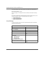
This chapter provides information about Generic Routing Encapsulation (GRE)
tunnels and instructions for configuring them.
305753-A Rev 00
Topic
Page
How GRE Tunneling Works
2-2
Avoiding IP Tunnel Misconfiguration
2-5
Creating a Generic Routing Encapsulation Tunnel
2-7
Adding and Deleting Protocols for GRE Tunnels
2-11
Configuring a Remote Tunnel End Point
2-15
2-1
Configuring GRE, NAT, RIPSO, and BFE Services
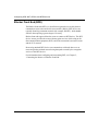
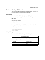
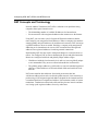
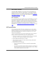
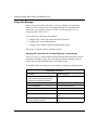
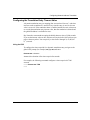
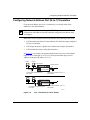
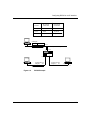
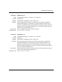
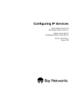
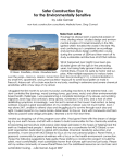
How GRE Tunneling Works
A simple point-to-point GRE tunnel terminates at router interfaces at each end of
the tunnel (Figure 2-1). Each of these interfaces has at least two addresses: a
physical address and one or more logical addresses. The physical address, which
is always an IP address, is visible to the devices making up the intervening
network cloud.
Local logical
host interface
Remote logical
host interface
Host
A
Host
B
Router
1
Router
2
GRE tunnel
Local physical
router interface
Remote physical
router interface
IP0095A
Figure 2-1.
Simple GRE Tunnel Components
At each tunnel end point, there is one logical address for each protocol configured
for encapsulation over the tunnel (IP or IPX). The logical addresses are not visible
to the devices that make up the intervening network cloud. They are private
addresses, visible only to the networks on either side of the tunnel.
2-2
305753-A Rev 00
Configuring GRE Tunnels
The GRE tunnel can use any IP interface configured on the router as a physical
end point. To maximize the robustness of the tunnel, use a circuitless IP address as
a tunnel’s physical end point whenever possible (see Configuring IP, ARP, RIP,
and OSPF Services).
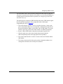
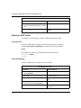
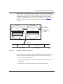
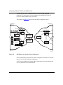
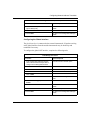
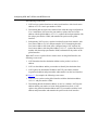
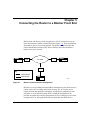
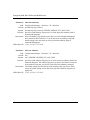
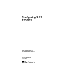
The following steps explain how GRE tunneling takes place. GRE tunnels support
both IP and IPX encapsulation. The example describes a GRE tunnel
encapsulating IP (refer to Figure 2-2):
305753-A Rev 00
1.
The router interface on router 1 receives a packet from host 1, looks up the
packet’s destination address in its routing table, and determines that the next
hop to the destination address is the remote end of a GRE tunnel. The router
interface queues the packet at the tunnel interface for GRE encapsulation.
2.
Router 1 adds a GRE header to the packet and sends the packet to IP.
3.
IP looks up the route to the remote tunnel end point and sends the
GRE-encapsulated packet to the appropriate next-hop address.
4.
The remote tunnel interface on router 2 removes the outer IP header and the
GRE header.
5.
The remote router interface looks up the packet’s destination address in its
routing table and chooses the next hop to reach host 2.
2-3
Configuring GRE, NAT, RIPSO, and BFE Services
Router 2
Router 1
Internet/Intranet
Host
1
Router
interface
Host
2
Tunnel
interface
Tunnel
Router
interface interface
MAC header
10.0.0.1 Source IP address
8.0.0.2 Destination IP address
MAC header
Source IP address 10.0.0.1
Destination IP address 8.0.0.2
data
data
MAC header
11.0.0.10 Source IP address
11.0.0.20 Destination IP address
GRE header
10.0.0.1 Source IP address
8.0.0.2 Destination address
data
Key
Transport protocol
Passenger protocol
IP0064A
Figure 2-2.
2-4
GRE Tunnel Encapsulating the IP Protocol
305753-A Rev 00
Configuring GRE Tunnels
Avoiding IP Tunnel Misconfiguration
Note: If you are using GRE tunneling to encapsulate the IPX protocol, skip
this section. The requirements discussed below do not apply to tunnels
encapsulating IPX.
Before configuring a tunnel encapsulating IP, you should be aware of a limitation
inherent in the use of all tunnels, including GRE tunnels. A tunnel is a virtual
point-to-point connection between two routers that are actually several hops apart.
This point-to-point connection can hide the real distance between the routers from
portions of the network, leading to unintended, suboptimal routing decisions and
in some cases, to routing loops.
In particular, if a router at one end of a tunnel determines that the best route to the
remote physical end point of the tunnel is through the tunnel itself, a loop, internal
to the router, occurs and prevents the tunnel from operating. You must configure
one of the following at each end of the tunnel to prevent routing loops:
•
Announce policy
•
Accept policy
•
Static route
The best choice depends on the network topology to which it is applied.
Note: When configuring a tunnel with IP encapsulation, you must implement
an announce or accept policy or a static route at each end of the tunnel for the
tunnel to operate correctly.
Announce Policies
An announce policy governs the advertisement of routing information. When
preparing a routing advertisement, IP consults its announce policies to determine
whether or not to advertise the route. For GRE tunneling, you can configure an
announce policy for each routing protocol (RIP, OSPF, BGP) configured on the
logical tunnel interface to block the advertisement of a range of network addresses
that contains the tunnel’s local physical interface address. For information about
configuring RIP and OSPF announce policies, see Configuring IP, ARP, RIP, and
OSPF Services. For information about configuring BGP announce policies, see
Configuring IP Exterior Gateway Protocols (BGP and EGP).
305753-A Rev 00
2-5
Configuring GRE, NAT, RIPSO, and BFE Services
The disadvantage of using an announce policy is that it prevents the advertisement
of other subnets within the blocked range. Depending on the network topology,
this configuration may not be desirable.
Accept Policies
An accept policy governs the addition of new routes to the routing tables. For
GRE tunneling, you can configure an accept policy for each routing protocol (RIP,
OSPF, BGP) configured on the logical tunnel interface to block the receipt of
advertisements from a range of network addresses that contains the tunnel’s
remote physical interface address. For information about configuring RIP and
OSPF accept policies, see Configuring IP, ARP, RIP, and OSPF Services. For
information about configuring BGP accept policies, see Configuring IP Exterior
Gateway Protocols (BGP and EGP).
The disadvantage of using an accept policy is that it prevents the receipt of
advertisements of subnets contained in the blocked range. Depending on the
network topology, this configuration may not be desirable.
Static Routes
A static route is a route configuration that designates a specific router within the
intervening network cloud as the next hop to the remote physical tunnel end point.
Because static routes take precedence over routes that the router learns
dynamically from routing protocols, this configuration forces the router to direct
packets through the cloud to reach the tunnel’s remote physical address.
The disadvantage of using a static route is that it is fixed. If the path through the
chosen next hop to the remote tunnel end point goes down, the tunnel goes down
as well until you manually reconfigure the static route. Similarly, even if the path
through the chosen next hop becomes more costly than the path through some
other attached router, the tunnel continues to use the costlier path unless you
manually intervene.
Note: When configuring a static route, be careful not to inadvertently create a
loop.
2-6
305753-A Rev 00
Configuring GRE Tunnels
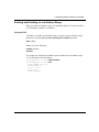
Creating a Generic Routing Encapsulation Tunnel
You can create up to 64 GRE tunnels on one router; each GRE tunnel can have
multiple end points. You can configure up to 256 remote tunnel end points
distributed over the configured GRE tunnels.
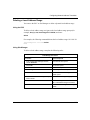
Adding a GRE Tunnel
When you add a GRE tunnel, you assign the tunnel a name and an IP address. The
IP address is the router interface used as the local physical end point for this
tunnel. The IP address must be that of an existing physical router IP interface.
This address is visible to the network cloud that the tunnel passes through.
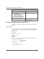
Use the BCC or Site Manager to add a GRE tunnel to the router.
Using the BCC
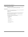
To add a GRE tunnel:
1.
Navigate to the box or stack prompt and enter the following command:
tunnels
The tunnels prompt appears.
2.
Navigate to the tunnels prompt (for example, box; tunnels) and enter the
following command:
gre name <name> local-address <address>
name is a unique name for this tunnel.
address is a valid IP address of a local router interface expressed in
dotted-decimal notation.
For example, the following command sequence creates the tunnel boston with the
local physical end point 197.1.2.3 and verifies the addition:
tunnels# gre name boston local-address 197.1.2.3
gre/boston# info
name boston
local-address 197.1.2.3
state enabled
305753-A Rev 00
2-7
Configuring GRE, NAT, RIPSO, and BFE Services
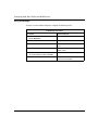
Using Site Manager
To add a GRE tunnel, complete the following tasks:
Site Manager Procedure
You do this
System responds
1. In the Configuration Manager window,
choose Protocols.
The Protocols menu opens.
2. Choose IP.
The IP menu opens.
3. Choose GRE.
The GRE Create Tunnels List window
opens.
4. Click on Add Tunnel.
The Create GRE Tunnel window opens.
5. Set the following parameters:
• IP Interface
• Tunnel Name
Click on Help or see the parameter
descriptions beginning on page A-3.
6. Click on OK.
You return to the GRE Create Tunnels
List window.
7. Go to “Adding and Deleting Protocols for
GRE Tunnels” on page 2-11 to add a
protocol for the GRE tunnel that you just
configured.
2-8
305753-A Rev 00
Configuring GRE Tunnels
Enabling or Disabling a GRE Tunnel
When you create a GRE tunnel, the tunnel is enabled by default. You can use the
BCC or Site Manager to disable or reenable a GRE tunnel.
Using the BCC
To enable or disable a GRE tunnel, navigate to the GRE tunnel interface prompt
(for example, box; tunnels; gre/boston) and enter the following command:
state <state>
state is one of the following:
enabled (default)
disabled
For example, the following command disables the tunnel boston and verifies the
change:
gre/boston# state disabled
gre/boston# info
name boston
local-address 197.1.2.3
state disabled
Using Site Manager
To enable or disable a GRE tunnel, complete the following tasks:
Site Manager Procedure
You do this
System responds
1. In the Configuration Manager window,
choose Protocols.
The Protocols menu opens.
2. Choose IP.
The IP menu opens.
3. Choose GRE.
The GRE Create Tunnels List window
opens.
4. Select a tunnel from the list of tunnels.
(continued)
305753-A Rev 00
2-9
Configuring GRE, NAT, RIPSO, and BFE Services
Site Manager Procedure (continued)
You do this
System responds
5. Set the Enable parameter. Click on Help
or see the parameter description on page
A-4.
6. Click on Apply.
The selected tunnel is enabled or
disabled.
Deleting a GRE Tunnel
Use the BCC or Site Manager to delete a GRE tunnel from the router.
Using the BCC
To delete a GRE tunnel, navigate to the GRE tunnel interface prompt (for
example, box; tunnels; gre/boston) and enter the following command:
delete
For example, the following command deletes the tunnel boston:
gre/boston# delete
tunnels#
Using Site Manager
To delete a GRE tunnel, complete the following tasks:
Site Manager Procedure
2-10
You do this
System responds
1. In the Configuration Manager window,
choose Protocols.
The Protocols menu opens.
2. Choose IP.
The IP menu opens.
3. Choose GRE.
The GRE Create Tunnels List window
opens.
4. Select the tunnel that you want to delete
from the list and click on Del Tunnel.
A confirmation window opens.
5. Click on OK.
You return to the GRE Create Tunnels
List window.
305753-A Rev 00
Configuring GRE Tunnels
Adding and Deleting Protocols for GRE Tunnels
The Bay Networks implementation of GRE tunneling supports IP and IPX
encapsulation. Use the BCC or Site Manager to add or delete a protocol for a GRE
tunnel.
Note: You can configure OSPF on either a GRE tunnel’s physical interfaces
or its logical interfaces, but not on both. When configuring OSPF on a GRE
tunnel, disable MTU mismatch detection. If the MTU mismatch parameter is
enabled, an OSPF adjacency may fail to form over the tunnel.
Adding a Protocol to a GRE Tunnel
When you add a protocol to a tunnel, you are configuring its local logical
interface. This address is not visible to the network cloud that the tunnel passes
through.
Use the BCC or Site Manager to add a protocol to a GRE tunnel.
Using the BCC
You can use the BCC to add an IP or IPX protocol interface to a GRE tunnel.
Adding an IP Protocol Interface
To add an IP protocol interface to a GRE tunnel, navigate to the GRE tunnel
interface prompt (for example, box; tunnels; gre/boston) and enter:
ip address <address> mask <address>
address is the valid IP address at the local end of the tunnel expressed in
dotted-decimal notation.
mask is the mask associated with the IP address.
For example, the following command adds the IP interface 9.9.9.1/255.255.255.0
to the tunnel boston:
gre/boston# ip address 9.9.9.1 mask 255.255.255.0
For a complete description of IP interface configuration, see Configuring IP, ARP,
RIP, and OSPF Services.
305753-A Rev 00
2-11
Configuring GRE, NAT, RIPSO, and BFE Services
Adding an IPX Protocol Interface
To add an IPX protocol interface to a GRE tunnel, navigate to the GRE tunnel
interface prompt (for example, box; tunnels; gre/boston) and enter:
ipx address <address> host-address <host_address>
address is a valid IPX network ID. The format is a four-byte hexadecimal string
of up to eight characters.
host_address is a valid IPX host address that is unique within the IPX
internetwork. Enter up to four characters in hexadecimal format. The IPX host
address maps to a physical data link layer address on a specific circuit or physical
interface.
The following example adds the IPX interface 00112233 to the tunnel boston:
gre/boston# ipx address 00112233 host-address 4411
For a complete description of IPX interface configuration, see Configuring IPX
Services.
Using Site Manager
To add a protocol to a GRE tunnel, complete the following tasks:
Site Manager Procedure
You do this
System responds
1. In the Configuration Manager window,
choose Protocols.
The Protocols menu opens.
2. Choose IP.
The IP menu opens.
3. Choose GRE.
The GRE Create Tunnels List window
opens.
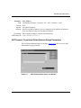
4. Choose a tunnel from the list and click on
Add/Del Prot.
The Select Protocols window opens.
5. Choose one or more protocols from the list The appropriate protocol configuration
and click on OK.
windows open.
For information about any parameter, click
on Help or see the appropriate protocol
guide.
6. Click on Done.
2-12
You return to the Configuration Manager
window.
305753-A Rev 00
Configuring GRE Tunnels
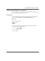
Enabling or Disabling a Protocol
You can use the BCC or Site Manager to enable or disable a protocol on a GRE
tunnel.
Using the BCC
To enable or disable a protocol, navigate to the protocol interface prompt (for
example, box; tunnels; gre/boston; ip 9.9.9.1/255.255.255.0) and enter:
state <state>
state is one of the following:
enabled (default)
disabled
For example, the following command disables the IP protocol interface 9.9.9.1/
255.255.255.0:
ip/9.9.9.1/255.255.255.0# state disabled
Using Site Manager
To enable or disable an IP or IPX interface on a GRE tunnel, complete the
following tasks:
Site Manager Procedure
You do this
System responds
1. In the Configuration Manager window,
choose Protocols.
The Protocols menu opens.
2. Choose IP or IPX.
The IP or IPX menu opens.
3. Choose Interfaces.
The IP Interface List window or the IPX
Interfaces window opens.
4. Click on the interface that you want to
enable or disable.
Site Manager displays the parameter
values for that interface.
5. Set the Enable parameter.
6. Click on Done.
305753-A Rev 00
You return to the Configuration Manager
window.
2-13
Configuring GRE, NAT, RIPSO, and BFE Services
Deleting a Protocol from a GRE Tunnel
Use the BCC or Site Manager to delete a protocol from a GRE tunnel.
Using the BCC
To delete a protocol from a GRE tunnel, navigate to the protocol interface prompt
(for example, box; tunnels; gre/boston; ip 9.9.9.1/255.255.255.0) and enter:
delete
For example, the following command deletes the IP protocol interface from the
tunnel boston:
ip/9.9.9.1/255.255.255.0# delete
gre/boston#
Using Site Manager
To delete a protocol from a GRE tunnel, complete the following tasks:
Site Manager Procedure
You do this
System responds
1. In the Configuration Manager window,
choose Protocols.
The Protocols menu opens.
2. Choose IP.
The IP menu opens.
3. Choose GRE.
The GRE Create Tunnels List window
opens.
4. Select a tunnel from the list and click on
Add/Del Prot.
The Select Protocols window opens.
5. Deselect the protocol.
6. Click on OK.
2-14
You return to the GRE Create Tunnels
List window.
305753-A Rev 00
Configuring GRE Tunnels
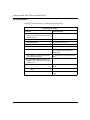
Configuring a Remote Tunnel End Point
A remote tunnel end point can be any IP interface configured on a Bay Networks
router or another router that complies with RFCs 1701 and 1702. To maximize the
robustness of the tunnel, use a circuitless IP address as a tunnel’s physical end
point whenever possible (see Configuring IP, ARP, RIP, and OSPF Services).
Because a circuitless IP address is associated with the whole router, not one
physical interface, the tunnel operates as long as any slot that has a working IP
interface stays up.
Adding a Remote Tunnel End Point
When you configure a remote tunnel end point, you assign it a name and specify
the IP address of the remote physical interface, as well as the IP and IPX addresses
of the remote logical interfaces. The physical interface is the physical router
interface at the remote end of the tunnel. This address is visible to the network
cloud that the tunnel passes through. The remote logical interface is not visible to
the network cloud.
Use the BCC or Site Manager to add a remote tunnel end point to a GRE tunnel.
Using the BCC
To configure a remote tunnel end point, perform the following steps:
1.
Configure the remote physical end point.
2.
Configure the remote logical interface.
Step 1. Configuring a Remote Physical End Point
To configure a remote tunnel end point, navigate to the GRE tunnel interface
prompt (for example, box; tunnels; gre/boston) and enter:
remote-endpoint <name> address <address>
name is the unique name for the remote end of the tunnel.
address is the valid IP address of the router interface at the remote end of the GRE
tunnel entered in dotted-decimal notation.
305753-A Rev 00
2-15
Configuring GRE, NAT, RIPSO, and BFE Services
For example, the following command sequence configures the remote end point
austin with the physical interface 197.1.2.4 and verifies the entry:
gre/boston#
remote-endpoint austin address 197.1.2.4
remote-endpoint/austin# info
name austin
address 197.1.2.4
logical-ip-address 0.0.0.1
logical-ipx-address 000000000001
state enabled
Note: When you configure a remote physical end point, the BCC
automatically inserts a default address value for the remote logical interface.
For IP, the default address is 0.0.0.1; for IPX, it is 00000000001. These
addresses are not valid. Until you configure valid logical addresses, the tunnel
will not come up.
Step 2. Configuring a Remote Logical Interface
Using the BCC, you can configure a logical interface for a remote end point.
Configuring a Remote Logical IP Interface
To configure a remote logical IP interface, navigate to the remote GRE tunnel
interface prompt (for example, box; tunnels; gre/boston; remote-endpoint/
austin) and enter:
logical-ip-address <address>
address is a valid IP address expressed in dotted-decimal notation.
For example, the following configures the remote GRE tunnel logical IP interface
for the remote end point austin to 9.9.9.2 and verifies the change:
remote-endpoint/austin# logical-ip-address 9.9.9.2
remote-endpoint/austin# info
name austin
address 197.1.2.4
logical-ip-address 9.9.9.2
logical-ipx-address 000000000001
state enabled
2-16
305753-A Rev 00
Configuring GRE Tunnels
Configuring a Remote Logical IPX Interface
To configure a remote logical IPX interface, navigate to the remote GRE tunnel
interface prompt (for example, box; tunnels; gre/boston; remote-endpoint/
austin) and enter:
logical-ipx-address <address>
address is a valid IPX address in hexadecimal notation.
For example, the following command sequence configures the remote logical IPX
interface 00112255 for the remote end point austin and verifies the change:
remote-endpoint/austin# logical-ipx-address 00112255
remote-endpoint/austin# info
name austin
address 197.1.2.4
logical-ip-address 9.9.9.2
logical-ipx-address 00112255
state enabled
Using Site Manager
To configure a remote tunnel end point, complete the following tasks:
Site Manager Procedure
You do this
System responds
1. In the Configuration Manager window,
choose Protocols.
The Protocols menu opens.
2. Choose IP.
The IP menu opens.
3. Choose GRE.
The GRE Create Tunnels List window
opens.
4. Choose a tunnel from the list and click on
Remote Conn.
The GRE Remote Connections List
window opens.
5. Click on Add.
The Create GRE Remote Connection
window opens.
(continued)
305753-A Rev 00
2-17
Configuring GRE, NAT, RIPSO, and BFE Services
Site Manager Procedure (continued)
You do this
System responds
6. Set the following parameters:
• Connection Name
• Remote Physical IP Address
• Remote Logical IP Address
• Remote Logical IPX Address (hex)
Click on Help or see the parameter
descriptions beginning on page A-5.
7. Click on OK.
You return to the GRE Remote
Connections List window.
Enabling or Disabling a Remote Tunnel End Point
Use the BCC or Site Manager to enable or disable a remote tunnel end point on a
GRE tunnel.
Using the BCC
To enable or disable a remote tunnel end point, navigate to the remote GRE tunnel
interface prompt (for example, box; tunnels; gre/boston; remote-endpoint/
austin) and enter:
state <state>
state is one of the following:
enabled (default)
disabled
For example, the following command sequence disables the remote tunnel end
point austin and verifies the change:
remote-endpoint/austin# state disabled
remote-endpoint/austin# info
name austin
address 197.1.2.4
logical-ip-address 9.9.9.2
logical-ipx-address 00112255
state disabled
2-18
305753-A Rev 00
Configuring GRE Tunnels
Using Site Manager
To enable or disable a remote tunnel end point, complete the following tasks:
Site Manager Procedure
You do this
System responds
1. In the Configuration Manager window,
choose Protocols.
The Protocols menu opens.
2. Choose IP.
The IP menu opens.
3. Choose GRE.
The GRE Create Tunnels List window
opens.
4. Click on Remote Conn.
The GRE Remote Connections List
window opens.
5. Select the remote tunnel end point from
the list.
6. Set the Enable parameter. Click on Help
or see the parameter description on page
A-4.
7. Click on OK.
The selected tunnel end point is enabled
or disabled.
Deleting a Remote Tunnel End Point
Use the BCC or Site Manager to delete a remote tunnel end point on a GRE
tunnel.
Using the BCC
To delete a remote tunnel end point, navigate to the remote GRE tunnel interface
prompt (for example, box; tunnels; gre/boston; remote-endpoint/austin) and
enter the following command:
delete
For example, the following command deletes the remote tunnel end point austin:
remote-endpoint/austin# delete
305753-A Rev 00
2-19
Configuring GRE, NAT, RIPSO, and BFE Services
Using Site Manager
To delete a remote tunnel end point, complete the following tasks:
Site Manager Procedure
2-20
You do this
System responds
1. In the Configuration Manager window,
choose Protocols.
The Protocols menu opens.
2. Choose IP.
The IP menu opens.
3. Choose GRE.
The GRE Create Tunnels List window
opens.
4. Click on Remote Conn.
The GRE Remote Connections List
window opens.
5. Choose the remote tunnel end point that
you want to delete and click on Delete.
A confirmation window opens.
6. Click on OK.
You return to the GRE Remote
Connections List window.
305753-A Rev 00
Chapter 3
Configuring Network Address Translation
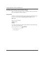
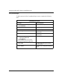
This chapter describes NAT and provides instructions for configuring NAT on a
router.
305753-A Rev 00
Topic
Page
NAT Concepts and Terminology
3-2
Starting NAT Services
3-11
Starting NAT Synchronization
3-18
Customizing NAT Global Parameters
3-22
Customizing a NAT Interface
3-31
Configuring Static Address Translation
3-38
Configuring Dynamic Local Address Ranges
3-43
Configuring Dynamic Global Address Ranges
3-48
Configuring Network Address Port (N-to-1) Translation
3-53
Customizing NAT Synchronization Parameters
3-58
Configuring NAT Synchronization Peers
3-65
3-1
Configuring GRE, NAT, RIPSO, and BFE Services
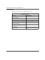
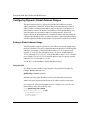
NAT Concepts and Terminology
Network Address Translation (NAT) offers a solution to two problems facing
companies that require Internet access:
•
The diminishing number of available IP addresses for Internet hosts
•
Private networks with unregistered addresses that cannot access the Internet
Using NAT, you can create a pool of registered IP network addresses that the
router maps to your unregistered local addresses. Where a company does not have
enough globally unique IP addresses for each host on its network, NAT can assign
a global IP address to hosts as needed. Similarly, a company using unregistered
addressing on its internal network can use NAT to translate those unregistered
addresses into registered addresses for making external connections.
Implementing NAT does not require widespread changes to a network’s hosts or
routers. You configure NAT on routers bordering the private and global networks.
Routers are configured with local and globally unique address ranges.
•
•
IP addresses inside the local network (local addresses) are not globally unique
or are nonstandard. They are never advertised outside the local network.
The globally unique addresses (global addresses) must be standard registered
addresses. Global addresses are advertised both within and outside the local
network.
NAT routers translate host addresses from inside private networks into
well-known addresses that can be used in the global network. On its return trip, a
packet using a NAT-assigned registered address destined for the internal network
is translated back into its original local address. NAT maintains a table of current
translations. Translations remain in the table until they become inactive and time
out, freeing up the registered address for use by other hosts.
3-2
305753-A Rev 00
Configuring Network Address Translation
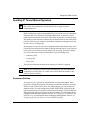
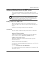
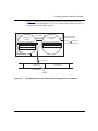
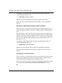
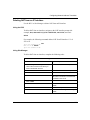
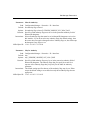
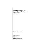
How NAT Works
In the example that follows, company A uses NAT to obtain global Internet access
for its hosts. Hosts on company A’s network need access to resources in company
B’s network. Company B is located in a different network on the Internet. Its
addresses are registered. NAT is configured on the router bordering company A’s
network and the global network. NAT enables communication between the
networks of company A and company B without requiring either company to
restructure its existing network.
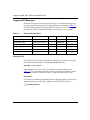
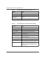
The network administrator at company A configures NAT to detect the following
ranges of unregistered local addresses:
•
•
•
10.0.0.0 through 10.255.255.255
15.0.0.0 through 15.255.255.255
50.1.1.0 through 50.1.1.255
The network administrator also configures the following ranges of registered
global addresses:
305753-A Rev 00
•
192.55.10.0 through 192.55.10.255
•
192.20.10.0 through 192.20.10.255
3-3
Configuring GRE, NAT, RIPSO, and BFE Services
In Figure 3-1, a packet from company A’s network with unregistered source
address 10.0.0.15 is sent to a destination address in company B’s network. The
destination is a globally recognized registered address, 192.100.20.2. The packet
follows normal IP routing to the NAT border router at the egress point in company
A.
Company A
Company B
Registered destination address
50.1.1.52
192.100.20.2
Boston
10.0.0.50
15.0.0.20
London
New York
Chicago
(NAT router)
New York
Atlanta
10.0.0.1
Santa Clara
10.0.0.15
Houston
15.0.0.45
Unregistered source address
IP0051A
Figure 3-1.
3-4
Network Address Translation Example
305753-A Rev 00
Configuring Network Address Translation
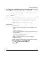
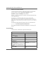
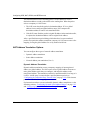
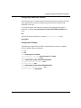
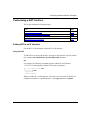
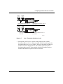
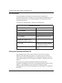
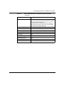
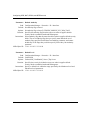
When the router’s NAT interface receives a packet, the NAT router extracts the
source address, first checking whether the packet’s source address falls within a
configured local address range. If it does, NAT compares the source address
against existing address translation entries in an internal table. In Figure 3-2, the
NAT router detects a packet on a NAT interface that contains the address
10.0.0.15.
NAT router
Local address
range list
Global address
range list
10.0.0.0 to 10.255.255.255
192.55.10.0 to 192.55.10.255
15.0.0.0 to 15.255.255.255
192.20.10.0 to 192.20.10.255
Current local/global
mapping entry list:
10.0.0.1
10.0.0.2
192.55.10.1
192.55.10.2
50.1.1.0 to 50.1.1.255
IP packet
10.0.0.15
Source address
192.100.20.2
Destination address
IP0052A
Figure 3-2.
NAT Detects the Source Address
If the inside host’s source address does not appear in the translation table and is
within a configured local address range, the NAT router does the following:
305753-A Rev 00
1.
Creates a new entry for the host
2.
Dynamically assigns the next available registered IP address from a global
address pool
3.
Changes the source address of the packet to the registered address
3-5
Configuring GRE, NAT, RIPSO, and BFE Services
In Figure 3-3, the NAT router dynamically translates the source address,
10.0.0.15, to one of the available global addresses (in this case, 192.55.10.3) and
creates a new entry in the local/global translation entry list.
Current local/global
mapping entry list:
NAT router
Local address
range list
Global address
range list
10.0.0.0 to 10.255.255.255
192.55.10.0 to 192.55.10.255
15.0.0.0 to 15.255.255.255
192.20.10.0 to 192.20.10.255
10.0.0.1
10.0.0.2
10.0.0.15
192.55.10.1
192.55.10.2
192.55.10.3
50.1.1.0 to 50.1.1.255
IP packet
10.0.0.15
Source address
192.100.20.2
Destination address
IP0053A
Figure 3-3.
3-6
NAT Updates the Local/Global Translation Entry List
305753-A Rev 00
Configuring Network Address Translation
In Figure 3-4, the NAT router then replaces the local source address (10.0.0.15)
with the translated global address (192.55.10.3) and sends the packet on its way to
its destination in company B’s network.
NAT router
Global address
range list
Local address
range list
10.0.0.0 to 10.255.255.255
192.55.10.0 to 192.55.10.255
15.0.0.0 to 15.255.255.255
192.20.10.0 to 192.20.10.255
Current local/global
mapping entry list:
10.0.0.1
10.0.0.2
192.55.10.1
192.55.10.2
50.1.1.0 to 50.1.1.255
IP packet
192.55.10.3
192.100.20.2
Destination address
Source address
10.0.0.15
IP0054A
Figure 3-4.
305753-A Rev 00
NAT Replaces the Local Address with a Registered Source Address
3-7
Configuring GRE, NAT, RIPSO, and BFE Services
The destination host uses the incoming packet’s source address to create a
destination address to send a packet back to the sending host. When the packet
arrives at company A’s NAT router:
1.
The NAT router checks the packet’s destination address. If it is a global
address from a configured global address range, NAT compares the
destination address to entries in its translation table.
2.
If the NAT router finds the packet’s original IP address in the translation table,
it replaces the destination address with its original local address.
After a specified timeout period during which there have been no translated
packets for a particular address translation, company A’s NAT router removes the
mapping, freeing the global address for use by another inside host.
NAT Address Translation Options
You can configure three types of network address translation:
•
Dynamic address translation
•
Static address translation
•
Network address port translation (N-to-1)
Dynamic Address Translation
Dynamic address translation creates a temporary mapping of an unregistered
address to a global address. The NAT router selects a global address from one or
more global address pools that you configure, and maps this address to the
unregistered address. The translation remains in a translation table for as long as it
is active. An idle entry is removed after a specified timeout period (see
“Configuring the Translation Entry Timeout Value” on page 3-29). If the timeout
parameter is disabled, the mapping is not removed.
For instructions on how to create and enable dynamic address translation, see the
following sections: “Configuring Dynamic Local Address Ranges” on page 3-43
and “Configuring Dynamic Global Address Ranges” on page 3-48.
3-8
305753-A Rev 00
Configuring Network Address Translation
Static Address Translation
Using static address translation, you can create a one-to-one translation of an
unregistered local host address to a global address. A static address translation
mapping does not time out, but remains configured until you disable or delete it.
For instructions on how to create and enable static translation, see “Configuring
Static Address Translation” on page 3-38.
N-to-1 Translation
N-to-1 translation allows you to translate a range of local IP addresses on a private
network into a single global IP address. The router maps a local address to the
global address, assigning it a unique Transmission Control Protocol (TCP) port
number. N-to-1 mappings are removed after a specified timeout period, unless the
timeout parameter is disabled. For instructions on how to configure N-to-1
translation, see “Configuring Network Address Port (N-to-1) Translation” on page
3-53.
NAT Synchronization
NAT synchronization allows NAT routers configured as peers to share address
translation information. If one NAT router fails, traffic can be rerouted to a peer
NAT router operating in the same synchronized configuration. Up to 10 NAT
routers can be synchronized.
A NAT router sends updates to peer routers each time that it creates or deletes a
dynamic translation. Synchronization works in the following manner:
305753-A Rev 00
1.
When router A performs a new translation, it adds the entry to its own table
and sends (via TCP connection) an update to its peer, router B.
2.
Router B adds the translation entry to its table.
3.
If the translation entry times out, router A deletes the entry and sends the
deletion update to router B.
4.
Router B does one of the following:
•
Deletes the translation if it has not received traffic using that address
translation.
•
Or, if it has received traffic using that address translation, router B ignores
the deletion update and sends a new translation update to router A. Router
A then adds the translation back into its table.
3-9
Configuring GRE, NAT, RIPSO, and BFE Services
A router does not “own” a translation unless it receives traffic using that
translation. If a router does not own a translation, it cannot delete it unless it
receives a deletion update from a peer router.
The example in Figure 3-5 shows two NAT routers configured as peers.
Company A
Company B
50.1.1.52
192.100.20.2
Boston
10.0.0.50
15.0.0.20
London
New York
Springfield
(NAT router 1)
New York
Atlanta
10.0.0.1
Springfield
(NAT router 2)
Santa Clara
10.0.0.15
Houston
15.0.0.45
IP0051X
Figure 3-5.
NAT Routers in a Synchronized Configuration
NAT synchronization works between routers configured as client/servers and also
those serving in load-balancing configurations.
A NAT router synchronizes dynamic address translations only. Static address and
N-to-1 translations are not synchronized.
3-10
305753-A Rev 00
Configuring Network Address Translation
Starting NAT Services
You can use the BCC or Site Manager to start NAT on the router. For instructions
on how to start and use the BCC or Site Manager, see one of these guides:
•
•
Using the Bay Command Console (BCC)
Configuring and Managing Routers with Site Manager
Using the BCC
To get NAT up and running on a router using default values for most parameters:
1.
Add NAT to the router.
2.
Specify at least one local address range to be translated.
3.
Specify at least one global address range to use when translating a local
address.
4.
Specify the local NAT interface.
5.
Specify the global NAT interface.
These steps are described in the following sections.
Adding NAT to the Router
To add NAT to the router, navigate to the global IP prompt (for example, box; ip)
and enter:
nat
Specifying a Local Address Range for NAT Translation
The local address range tells the router which local unregistered host addresses to
translate into global addresses. You must configure at least one local address
range.
The local address range is specified as a base address and a prefix length (from 1
through 32 decimal). The prefix length determines the number of available local
addresses. For example, if the base address is 10.1.10.0 and its prefix length is 24
(255.255.255.0), then the address range you specify includes addresses 10.1.10.0
through 10.1.10.255.
305753-A Rev 00
3-11
Configuring GRE, NAT, RIPSO, and BFE Services
To configure a local address range, navigate to the global NAT prompt (for
example, box; ip; nat) and enter:
nat# local-range <address>/<mask>
address is the base local address expressed in dotted-decimal notation.
mask is the prefix length associated with the IP address expressed in decimal
notation.
Specifying a Global Address Range for NAT Translation
The global address range tells the router which registered global addresses to use
when translating local addresses. You must configure at least one global address
range.
The global address range is specified as a base address and a prefix length (from 1
through 32 decimal). The prefix length determines the number of available global
addresses. For example, if the base address is 197.1.2.0 and its prefix length is 24
(255.255.255.0), then the address range you specify includes addresses 197.1.2.0
through 197.1.2.255.
To configure a global address range, navigate to the global NAT prompt (for
example, box; ip; nat) and enter:
nat# global-range <address>/<mask>
address is the base global IP address expressed in dotted-decimal notation.
mask is the prefix length associated with the IP address expressed in decimal
notation.
Configuring a Local NAT Interface
The local interface is connected to the internal network that includes the networks
within the local address range. The router performs address translation only on
packets from local hosts included in the local address range.
To specify the local NAT interface, navigate to the appropriate IP interface prompt
(for example, box; ethernet/2/2; ip/192.132.45.3/255.255.255.0) and enter:
nat
3-12
305753-A Rev 00
Configuring Network Address Translation
Configuring a Global NAT Interface
The global interface is connected to the external internetwork. IP packets arriving
at the global interface from the outside internetwork may be looked up and
translated if necessary.
To specify the global NAT interface, navigate to the appropriate IP interface
prompt (for example, box; ethernet/2/1; ip/192.132.22.10/255.255.255.0) and
enter:
nat
At the NAT interface prompt (for example, nat/192.132.22.10), enter:
type global
Configuration Example
The following example shows the BCC commands that you enter to configure
NAT for dynamic address translation:
box# ip
ip# nat
nat# local-range 10.1.10.0/24
local-range/10.1.10.0/24# global-range 197.1.2.0/24
global-range/197.1.2.0/24# box
box# ethernet/2/2; ip/192.132.45.3/255.255.255.0
ip/192.132.45.3/255.255.255.0# nat
nat/192.132.45.3# box
box# ethernet/2/1; ip/192.132.22.10/255.255.255.0
ip/192.132.22.10/255.255.255.0# nat
nat/192.132.22.10# type global
305753-A Rev 00
3-13
Configuring GRE, NAT, RIPSO, and BFE Services
Using Site Manager
Before you can start NAT on the router, you must configure a circuit that the
protocol can use as an interface to an attached network. For information and
instructions, see Configuring Ethernet, FDDI, and Token Ring Services or
Configuring WAN Line Services.
To start NAT on a router using Site Manager:
1.
Configure NAT on the router and on the local IP interface.
2.
Configure NAT on the global interface.
3.
Configure a local address range and a global address range.
These steps are described in the following sections.
Starting NAT on the Router and Specifying the Local Interface
The local interface is connected to the internal network that includes the networks
within the local address range. The router performs address translation only on
packets from local hosts included in the local address range.
To start NAT on the router and on a local interface, complete the following tasks:
Site Manager Procedure
You do this
System responds
1. In the Configuration Manager window,
click on the connector that you want to
configure as the NAT local interface.
The Edit Connector window opens.
2. Click on Edit Circuit.
The Circuit Definition window opens.
3. Choose Protocols.
The Protocols menu opens.
4. Choose Add/Delete.
The Select Protocols window opens.
5. Click on NAT.
6. Click on OK.
The NAT Global Configuration window
opens.
7. Click on OK to accept the default values
for NAT global parameters.
The NAT Interface Configuration window
opens.
(continued)
3-14
305753-A Rev 00
Configuring Network Address Translation
Site Manager Procedure (continued)
You do this
System responds
8. Click on OK to accept the default interface You return to the Circuit Definition
type for NAT (local).
window.
9. Choose File.
The File menu opens.
10. Choose Exit.
You return to the Configuration Manager
window.
Configuring the Global Interface
The global interface is connected to the external internetwork. IP packets arriving
at the global interface from the outside internetwork may be looked up and
translated if necessary.
To configure the global NAT interface, complete the following tasks:
Site Manager Procedure
You do this
System responds
1. In the Configuration Manager window,
click on the connector that you want to
configure as the NAT global interface.
The Edit Connector window opens.
2. Click on Edit Circuit.
The Circuit Definition window opens.
3. Choose Protocols.
The Protocols menu opens.
4. Choose Add/Delete.
The Select Protocols window opens.
5. Click on NAT.
6. Click on OK.
The NAT Interface Configuration window
opens.
7. Set the Interface Type parameter to
Global.
305753-A Rev 00
8. Click on OK.
You return to the Circuit Definition
window.
9. Choose File.
The File menu opens.
10. Choose Exit.
You return to the Configuration Manager
window.
3-15
Configuring GRE, NAT, RIPSO, and BFE Services
Configuring a Local and Global Address Range
The local address range tells the router which local unregistered host addresses to
translate into global addresses. The global address range tells the router which
registered global addresses to use when translating local addresses.You must
configure at least one local and one global address range.
You specify a local and a global address range as a base address and a prefix
length (from 1 through 32 decimal). The prefix length determines the number of
available local or global addresses. For example, if the base address is 197.1.2.0
and its prefix length is 24 (255.255.255.0), then the address range you specify
includes addresses 197.1.2.0 through 197.1.2.255.
To configure a local and a global address range, complete the following tasks:
Site Manager Procedure
You do this
System responds
1. In the Configuration Manager window,
choose Protocols.
The Protocols menu opens.
2. Choose IP.
The IP menu opens.
3. Choose NAT.
The NAT menu opens.
4. Choose Dynamic.
The NAT Dynamic menu opens.
5. Choose Local.
The NAT Local Address Range List
window opens.
6. Click on Add.
The NAT Local Address Range Add
window opens.
7. Set the following parameters:
• IP Address
• Prefix Length
Click on Help or see the parameter
descriptions beginning on page A-18.
8. Click on OK.
You return to the NAT Local Address
Range List window.
9. Click on Done.
You return to the Configuration Manager
window.
10. In the Configuration Manager window,
choose Protocols.
The Protocols menu opens.
11. Choose IP.
The IP menu opens.
(continued)
3-16
305753-A Rev 00
Configuring Network Address Translation
Site Manager Procedure (continued)
You do this
System responds
12. Choose NAT.
The NAT menu opens.
13. Choose Dynamic.
The NAT Dynamic menu opens.
14. Choose Global.
The NAT Global Address Range List
window opens.
15. Click on Add.
The NAT Global Address Range Add
window opens.
16. Set the following parameters:
• IP Address
• Prefix Length
Click on Help or see the parameter
descriptions beginning on page A-20.
17. Click on OK.
You return to the NAT Global Address
Range List window.
18. Click on Done.
You return to the Configuration Manager
window.
Where to Go Next
The instructions provided in “Starting NAT Services” are the minimal instructions
required to enable NAT operation with dynamic address translation on your router.
You can configure other types of address translation--static or N-to-1--or further
customize NAT operation.
Use the following table to determine where to go next.
305753-A Rev 00
If you want to
Go to
Start NAT synchronization.
“Starting NAT Synchronization” on page 3-18
Configure static address
translation.
“Configuring Static Address Translation” on page
3-38
Configure N-to-1 address
translation.
“Configuring Network Address Port (N-to-1)
Translation” on page 3-53
Change default settings for NAT
global parameters.
“Customizing NAT Global Parameters” on page 3-22
Change default settings for NAT
interface parameters.
“Customizing a NAT Interface” on page 3-31
3-17
Configuring GRE, NAT, RIPSO, and BFE Services
Starting NAT Synchronization
NAT synchronization allows up to 10 routers configured as peers to share NAT
address translation information. Routers in a synchronized configuration have
up-to-date address translation tables and can handle traffic that may be rerouted to
them if a peer router should shut down or fail.
To configure NAT synchronization, you configure each router as follows:
1.
Start NAT on the router (see “Starting NAT Services” on page 3-11).
2.
Enable synchronization.
3.
Assign the router a unique synchronized router ID. The synchronized router
ID must be unique among all peer routers. You must enter the synchronized
router ID in dotted-decimal notation, but the router ID does not need to be an
actual IP interface address.
4.
Configure the router with information about its synchronization peers,
including the synchronized router ID and IP address for each peer. The IP
address can be any valid IP interface.
Routers in a synchronized configuration must be identically configured for the
following parameters:
•
Synchronization port. This value is the TCP port that NAT routers use to
exchange translation updates. If you change it from its default of 670, be sure
to use the same port value for all routers in a synchronized configuration.
•
Local and global address ranges. These ranges must be the same on all peer
routers. Static and N-to-1 mappings are not synchronized and can remain
unique for each router.
You can use the BCC or Site Manager to configure NAT synchronization.
Note: You can configure a NAT router to accept translation updates without
generating updates of its own. To configure a router as a NAT synchronization
peer of this type, you must enable NAT and NAT synchronization on the router,
and include this router in the peer list of other NAT routers. However, you do
not configure address ranges or synchronization peers.
3-18
305753-A Rev 00
Configuring Network Address Translation
Using the BCC
To start NAT synchronization on a router using default values for most
parameters:
1.
Enable NAT synchronization on the router.
2.
Specify at least one synchronization peer.
Enabling NAT Synchronization
You must configure an IP interface on the router before you can enable NAT
synchronization. To enable NAT synchronization, navigate to the global NAT
prompt (for example, box; ip; nat) and enter:
synch enabled [synch-router-id <n.n.n.n>]
n.n.n.n can be any integer and must be unique for each peer router in a
synchronized configuration. Enter the value in the dotted-decimal format of an IP
address. A router IP address can be used as the ID.
If you enable synchronization without entering a synchronized router ID, the
router automatically inserts the IP address of an existing router IP interface.
If you want to set a different synchronized router ID, navigate to the global NAT
prompt (for example, box; ip; nat) and enter:
synch-router-id <n.n.n.n>
Adding NAT Synchronization Peers
To add a router to the list of synchronized peer routers, navigate to the global NAT
prompt (for example, box; ip; nat) and enter:
peer <synch_router_id> address <address>
synch_router_id is the unique ID assigned to the peer router.
address is the IP address of the interface that the peer router will use to make TCP
connections when sending or receiving address translations.
305753-A Rev 00
3-19
Configuring GRE, NAT, RIPSO, and BFE Services
Configuration Example
The following example shows the BCC commands that you enter to configure
NAT synchronization using an already configured IP interface as the synchronized
router ID:
box# ip; nat
nat# synch enabled
nat# peer 10.0.0.20 address 10.0.0.20
Using Site Manager
You must configure an IP interface on the router before enabling NAT
synchronization. If an IP interface already exists, you will be prompted to select
that interface as the synchronized router ID.
Enabling NAT Synchronization
To enable NAT synchronization, complete the following tasks:
Site Manager Procedure
You do this
System responds
1. In the Configuration Manager window,
choose Protocols.
The Protocols menu opens.
2. Choose IP.
The IP menu opens.
3. Choose NAT.
The NAT menu opens.
4. Choose Global.
The NAT Base Group Record window
opens.
5. Set the Synchronization parameter to
Enable. Click on Help or see the
parameter description on page A-10.
6. Click on OK.
You are prompted to accept a configured
IP interface as the synchronized router
ID.
You return to the Configuration Manager
7. Do one of the following:
window.
• To accept the IP address as the
synchronized router ID, click on Yes.
• To specify a different router ID, click on
No and set the Synch Router ID
parameter. Then click on OK.
3-20
305753-A Rev 00
Configuring Network Address Translation
Adding NAT Synchronization Peers
To add a router to the list of synchronized peer routers, complete the following
tasks:
Site Manager Procedure
You do this
System responds
1. In the Configuration Manager window,
choose Protocols.
The Protocols menu opens.
2. Choose IP.
The IP menu opens.
3. Choose NAT.
The NAT menu opens.
4. Choose Synch Peer.
The NAT Synchronization Peer List
window opens.
5. Click on Add.
The NAT Synchronization Peer Add
window opens.
6. Set the following parameters:
• Peer Synch Router ID
• Peer Address
Click on Help or see the parameter
descriptions beginning on page A-22.
305753-A Rev 00
7. Click on OK.
You return to the NAT Synchronization
Peer List window.
8. Click on Done.
You return to the Configuration Manager
window.
3-21
Configuring GRE, NAT, RIPSO, and BFE Services
Customizing NAT Global Parameters
To customize the way NAT operates on a router, modify NAT global attributes as
described under the following sections:
3-22
Topic
Page
Enabling and Disabling NAT on the Router
3-23
Configuring the Soloist Slot Mask
3-24
Logging NAT Messages
3-26
Enabling and Disabling Translation Entry Timeout
3-28
Configuring the Translation Entry Timeout Value
3-29
305753-A Rev 00
Configuring Network Address Translation
Enabling and Disabling NAT on the Router
You can use the BCC or Site Manager to enable or disable NAT on the router.
Using the BCC
To enable or disable NAT on a router, navigate to the global NAT prompt (for
example, box; ip; nat) and enter:
state <state>
state is one of the following:
enabled (default)
disabled
Using Site Manager
To enable or disable NAT on a router, complete the following tasks:
Site Manager Procedure
You do this
System responds
1. In the Configuration Manager window,
choose Protocols.
The Protocols menu opens.
2. Choose IP.
The IP menu opens.
3. Choose NAT.
The NAT menu opens.
4. Choose Global.
The NAT Base Group Record window
opens.
5. Set the Enable parameter. Click on Help
or see the parameter description on page
A-8.
6. Click on OK.
305753-A Rev 00
You return to the Configuration Manager
window.
3-23
Configuring GRE, NAT, RIPSO, and BFE Services
Configuring the Soloist Slot Mask
By default, the router uses any available slot for the NAT soloist. Use the BCC or
Site Manager to specify which slots can run as the NAT soloist.
Using the BCC
To specify the slots on which NAT can run as a soloist, navigate to the global NAT
prompt (for example, box; ip; nat) and enter:
slot-mask <slot>
slot can be one or more slots from 1 through 14. If you enter more than one slot
number, you must enclose the numbers in braces or in quotation marks. By
default, all slots (“all-slots”) are selected.
For example, the following command sequence selects slots 1 and 5 as the
preferred NAT soloist slots and verifies the change:
nat# slot-mask {1 5}
nat# info
slot-mask {1 5}
log-mask none
timeout enabled
synch disabled
synch-router-id 0.0.0.0
timeout-max 3600
synch-port 670
synch-idle-timer 120
synch-retransmit-timer 3
synch-retransmit-tries 5
state enabled
3-24
305753-A Rev 00
Configuring Network Address Translation
Using Site Manager
To specify the slots on which NAT can run as a soloist, complete the following
tasks:
Site Manager Procedure
You do this
System responds
1. In the Configuration Manager window,
choose Protocols.
The Protocols menu opens.
2. Choose IP.
The IP menu opens.
3. Choose NAT.
The NAT menu opens.
4. Choose Global.
The NAT Base Group Record window
opens.
5. Click in the Soloist Slot Mask field.
6. Click on Values.
Site Manager displays a list of slots.
7. Choose the slots that you want to specify
as available to run as a soloist. Click on
Help or see the parameter description on
page A-8.
Site Manager displays the binary values
that correspond to your slot selections in
the Soloist Slot Mask field.
For example, if a router has five slots, and
you choose slots 3 and 5, the binary
value 00101 appears in the Soloist Slot
Mask field. The leftmost bit represents
the slot with the lowest number.
8. Click on OK.
305753-A Rev 00
You return to the Configuration Manager
window.
3-25
Configuring GRE, NAT, RIPSO, and BFE Services
Logging NAT Messages
By default, the router does not log NAT messages. You can enable the logging of
messages by specifying the types of messages that the router should log. Table 3-1
lists the message types that can be logged by NAT software. If you enable logging,
the change is effective immediately (if there are any messages to be logged).
Table 3-1.
NAT Log Message Types
Message Type
Definition
Bit Position Hex Value
BCC Keyword
NAT_DBG_MIB_LOG
MIB-related events
0
0x00000001
mib
NAT_DBG_IP_LOG
Debug events at IP level
1
0x00000002
ip
NAT_DBG_FWD_LOG
Forwarding events
2
0x00000004
forwarding
NAT_DBG_MAPPING_LOG
Translation table events
3
0x00000008
mapping
NAT_DBG_AGING_LOG
Aging level events
4
0x00000010
aging
NAT_DBG_SYNCH_LOG
Synchronization events
5
0x00000020
synchronization
Using the BCC
To specify the types of log messages that are reported by NAT software, navigate
to the global NAT prompt (for example, box; ip; nat) and enter:
log-mask <mask_keyword>
mask_keyword can be one or more keywords representing the log type (see
Table 3-1). If you enter more than one keyword, you must enclose them in braces
or in quotation marks. The default is none. To select all log messages, enter:
log-mask all
For example, the following command enables the logging of NAT event messages
with the logging levels NAT_DBG_MIB_LOG and NAT_DBG_IP_LOG:
nat# log-mask {mib ip}
nat#
3-26
305753-A Rev 00
Configuring Network Address Translation
Using Site Manager
To specify the types of log messages that are reported by NAT software, complete
the following tasks:
Site Manager Procedure
You do this
System responds
1. In the Configuration Manager window,
choose Protocols.
The Protocols menu opens.
2. Choose IP.
The IP menu opens.
3. Choose NAT.
The NAT menu opens.
4. Choose Global.
The NAT Base Group Record window
opens.
5. Set the Log Mask parameter by clicking
on Values and selecting the message
types that you want to log.
Click on Help or see the parameter
description on page A-9.
305753-A Rev 00
6. Click on OK.
Site Manager displays the binary values
that correspond to your log message type
selections in the Log Mask field.
7. Click on OK.
You return to the Configuration Manager
window.
3-27
Configuring GRE, NAT, RIPSO, and BFE Services
Enabling and Disabling Translation Entry Timeout
By default, the router deletes expired NAT translation table entries. If there have
been no translated packets for a specific address mapping when the translation
entry timer expires, NAT software removes the entry from the dynamic translation
entry list, freeing the global address for another mapping.
Using the BCC
To enable or disable translation entry timeout, navigate to the global NAT prompt
(for example, box; ip; nat) and enter:
timeout <state>
state is one of the following:
enabled (default)
disabled
Using Site Manager
To change the translation entry timeout status, complete the following tasks:
Site Manager Procedure
You do this
System responds
1. In the Configuration Manager window,
choose Protocols.
The Protocols menu opens.
2. Choose IP.
The IP menu opens.
3. Choose NAT.
The NAT menu opens.
4. Choose Global.
The NAT Base Group Record window
opens.
5. Set the Mapping Entry Timeout
parameter. Click on Help or see the
parameter description on page A-9.
6. Click on OK.
3-28
You return to the Configuration Manager
window.
305753-A Rev 00
Configuring Network Address Translation
Configuring the Translation Entry Timeout Value
A dynamic translation entry (or mapping) has an associated “last-use” value that
increases each second that it is unused. Every time the entry is used, its last-use
value is reset to 0. If the translation timer is enabled, and the last-use value meets
or exceeds the translation entry timeout value, then the translation is deleted and
the global IP address is available for reuse.
Bay Networks recommends accepting the default timeout value of 3600 seconds.
If you set the timeout value too low, the timer will expire before NAT software can
process the next packet. You can specify a value from 0 through 2,147,483,647
(231) seconds.
Using the BCC
To configure the timeout period for a dynamic translation entry, navigate to the
global NAT prompt (for example, box; ip; nat) and enter:
timeout-max <timeout>
timeout is the duration of the timeout period in seconds.
For example, the following command configures a timeout period of 7200
seconds:
nat# timeout-max 7200
nat#
305753-A Rev 00
3-29
Configuring GRE, NAT, RIPSO, and BFE Services
Using Site Manager
To configure the timeout period for a dynamic translation entry, complete the
following tasks:
Site Manager Procedure
You do this
System responds
1. In the Configuration Manager window,
choose Protocols.
The Protocols menu opens.
2. Choose IP.
The IP menu opens.
3. Choose NAT.
The NAT menu opens.
4. Choose Global.
The NAT Base Group Record window
opens.
5. Set the Max Timeout parameter. Click on
Help or see the parameter description on
page A-9.
6. Click on OK.
3-30
You return to the Configuration Manager
window.
305753-A Rev 00
Configuring Network Address Translation
Customizing a NAT Interface
This section includes the following topics:
Topic
Page
Adding NAT to an IP Interface
3-31
Enabling and Disabling NAT on an Interface
3-33
Modifying the Interface Type
3-35
Deleting NAT from an IP Interface
3-37
Adding NAT to an IP Interface
Use the BCC or Site Manager to add NAT to an IP interface.
Using the BCC
To add NAT to an existing IP interface, navigate to an IP interface-specific prompt
(for example, box; ethernet/13/1; ip/1.2.3.4/255.0.0.0) and enter:
nat
For example, the following command sequence adds NAT to IP interface
1.2.3.4/255.0.0.0 and displays default NAT interface parameters:
ip/1.2.3.4/255.0.0.0# nat
nat/1.2.3.4# info
type local
state enabled
When you add NAT to an IP interface, it becomes a local interface by default. To
configure an interface as a global interface, set the type parameter to global.
305753-A Rev 00
3-31
Configuring GRE, NAT, RIPSO, and BFE Services
Using Site Manager
To add NAT to an IP interface, complete the following tasks:
Site Manager Procedure
You do this
System responds
1. In the Configuration Manager window,
The Edit Connector window opens.
click on the connector to which you want to
add NAT services.
2. Click on Edit Circuit.
The Circuit Definition window opens.
3. Choose Protocols.
The Protocols menu opens.
4. Choose Add/Delete.
The Select Protocols window opens.
5. Click on NAT.
Site Manager highlights the selection.
6. Click on OK.
If this is the first NAT interface on the
router, the NAT Global Configuration
window opens.
7. Click on OK to accept the default values
for NAT global parameters.
The NAT Interface Configuration window
opens.
8. Set the Interface Type parameter. Click
on Help or see the parameter description
on page A-13.
3-32
9. Click on OK.
You return to the Circuit Definition
window.
10. Choose File.
The File menu opens.
11. Choose Exit.
You return to the Configuration Manager
window.
305753-A Rev 00
Configuring Network Address Translation
Enabling and Disabling NAT on an Interface
When you add NAT to an IP interface, NAT is enabled by default. You can use the
BCC or Site Manager to enable or disable NAT.
Using the BCC
To enable or disable NAT on an interface, navigate to the NAT interface prompt
(for example, box; ethernet/13/1; ip/1.2.3.4/255.0.0.0; nat) and enter:
state <state>
state is one of the following:
enabled (default)
disabled
For example, the following command sequence disables NAT on IP interface
1.2.3.4/255.0.0.0 and verifies the change:
ip/1.2.3.4/255.0.0.0# nat
nat/1.2.3.4# state disabled
nat/1.2.3.4# info
type local
state disabled
305753-A Rev 00
3-33
Configuring GRE, NAT, RIPSO, and BFE Services
Using Site Manager
To enable or disable NAT on an interface, complete the following tasks:
Site Manager Procedure
You do this
System responds
1. In the Configuration Manager window,
choose Protocols.
The Protocols menu opens.
2. Choose IP.
The IP menu opens.
3. Choose NAT.
The NAT menu opens.
4. Choose Interface.
The NAT Interface List window opens.
5. Select the interface that you want to
enable or disable from the list.
6. Set the Enable parameter. Click on Help
or see the parameter description on page
A-13.
7. Click on Done.
3-34
You return to the Configuration Manager
window.
305753-A Rev 00
Configuring Network Address Translation
Modifying the Interface Type
The NAT router is configured with local and global interfaces. Local interfaces are
attached to the local network. When a packet arrives at the local interface, the
NAT router examines the packet’s source address to determine whether it should
be translated into a global address before forwarding. Global interfaces are
attached to the external network. When a packet arrives at the global interface, the
NAT router examines the packet’s destination address to determine whether it is
an existing translation.
By default, when you enable NAT on an IP interface, the interface type is set to
local. To configure an external interface, you must set the type to global.
Using the BCC
To modify the NAT interface type, navigate to the NAT interface prompt (for
example, box; ethernet/13/1; ip1.2.3.4/255.0.0.0; nat) and enter:
type <type>
type is one of the following:
local (default)
global
For example, the following command sequence changes the type for NAT
interface 197.1.2.3 from local to global and verifies the change:
standard/5/1# ip 197.1.2.3/8
ip/197.1.2.3/255.0.0.0# nat
nat/197.1.2.3# info
type local
state enabled
nat/197.1.2.3# type global
nat/197.1.2.3# info
type global
state enabled
305753-A Rev 00
3-35
Configuring GRE, NAT, RIPSO, and BFE Services
Using Site Manager
To modify the NAT interface type, complete the following tasks:
Site Manager Procedure
You do this
System responds
1. In the Configuration Manager window,
choose Protocols.
The Protocols menu opens.
2. Choose IP.
The IP menu opens.
3. Choose NAT.
The NAT menu opens.
4. Choose Interface.
The NAT Interface List window opens.
5. Select the interface that you want to
modify from the list.
6. Set the Interface Type parameter. Click
on Help or see the parameter description
on page A-13.
7. Click on Done.
3-36
You return to the Configuration Manager
window.
305753-A Rev 00
Configuring Network Address Translation
Deleting NAT from an IP Interface
Use the BCC or Site Manager to delete NAT from an IP interface.
Using the BCC
To delete NAT from an interface, navigate to the NAT interface prompt (for
example, box; ethernet/13/1; ip/1.2.3.4/255.0.0.0; nat/1.2.3.4) and enter:
delete
For example, the following command deletes NAT from IP interface 1.2.3.4/
255.0.0.0:
ip/1.2.3.4/255.0.0.0# nat
nat/1.2.3.4# delete
ip/1.2.3.4/255.0.0.0#
Using Site Manager
To delete NAT from an interface, complete the following tasks:
Site Manager Procedure
You do this
System responds
1. In the Configuration Manager window,
click on the connector from which you
want to delete NAT services.
The Edit Connector window opens.
2. Click on Edit Circuit.
The Circuit Definition window opens.
3. Choose Protocols.
The Protocols menu opens.
4. Choose Add/Delete.
The Select Protocols window opens. The
NAT button is checked to show that NAT
is enabled on the circuit.
5. Click on NAT.
305753-A Rev 00
6. Click on OK.
You return to the Circuit Definition
window.
7. Choose File.
The File menu opens.
8. Choose Exit.
You return to the Configuration Manager
window.
3-37
Configuring GRE, NAT, RIPSO, and BFE Services
Configuring Static Address Translation
Static address translation creates a one-to-one mapping of an unregistered local
host address to a registered global address. Static address mappings can be used
to:
•
Preserve a translation entry.
•
Create a connection from a host on the global network to a host on the local
network.
A static address translation does not time out when there is no traffic on the
interface. The translation remains fixed until you disable or delete it.
You can assign static address mappings from the same global address allocation
pool used for dynamic address translations. The router will not use the reserved
address for a dynamic allocation. However, if you try to configure a static address
mapping using a global IP address that is currently being used for a dynamic
translation, you receive an error message.
Adding a Static Address Mapping
Use the BCC or Site Manager to add a static address mapping.
Using the BCC
To add a static address mapping, navigate to the global NAT prompt (for example,
box; ip; nat) and enter:
static-map <local_address>/<global_address>
local_address is an unregistered local address of a host in your network. Enter the
local address in dotted-decimal notation.
global_address is the registered global address that you want to map to the local
address. Enter a valid global IP address in dotted-decimal notation.
3-38
305753-A Rev 00
Configuring Network Address Translation
For example, the following command sequence maps the local address 10.1.1.1 to
the global address 199.1.42.200 and verifies the entry:
nat# static-map 10.1.1.1/199.1.42.200
static-map/10.1.1.1/199.1.42.200# info
local-address 10.1.1.1
global-address 199.1.42.200
protocol none
local-port 0
global-port 0
state enabled
Note: The parameters protocol, local-port, and global-port are reserved for
future use. You cannot modify these parameters.
Using Site Manager
To add a static address mapping, complete the following tasks:
Site Manager Procedure
You do this
System responds
1. In the Configuration Manager window,
choose Protocols.
The Protocols menu opens.
2. Choose IP.
The IP menu opens.
3. Choose NAT.
The NAT menu opens.
4. Choose Static.
The NAT Static Translation List window
opens.
5. Click on Add.
The NAT Static Translation Add window
opens.
6. Set the following parameters:
• Local Address
• Global Address
Click on Help or see the parameter
descriptions beginning on page A-15.
305753-A Rev 00
7. Click on OK.
The static mapping pair appears in the list
of current mapping pairs.
8. Click on Done.
You return to the Configuration Manager
window.
3-39
Configuring GRE, NAT, RIPSO, and BFE Services
Enabling and Disabling a Static Address Mapping
When you add a static address mapping, it is enabled by default. You can use the
BCC or Site Manager to disable or reenable it.
Using the BCC
To enable or disable a static address mapping, navigate to the static map prompt
(for example, box; ip; nat; static-map/10.1.1.1/199.1.42.200) and enter:
state <state>
state is one of the following:
enabled (default)
disabled
For example, the following command disables the static mapping entry
10.1.1.1/199.1.42.200:
static-map/10.1.1.1/199.1.42.200# state disabled
3-40
305753-A Rev 00
Configuring Network Address Translation
Using Site Manager
To enable or disable a static address mapping, complete the following tasks:
Site Manager Procedure
You do this
System responds
1. In the Configuration Manager window,
choose Protocols.
The Protocols menu opens.
2. Choose IP.
The IP menu opens.
3. Choose NAT.
The NAT menu opens.
4. Choose Static.
The NAT Static Translation List window
opens.
5. Select the static mapping that you want to
enable or disable from the list.
6. Set the Enable parameter. Click on Help
or see the parameter description on page
A-15.
7. Click on Done.
You return to the Configuration Manager
window.
Deleting a Static Address Mapping
You can use the BCC or Site Manager to delete a static address mapping.
Using the BCC
To delete a static address mapping, navigate to the static map prompt (for
example, box; ip; nat; static-map/10.1.1.1/199.1.42.200) and enter:
delete
For example, the following command deletes the static address mapping
10.1.1.1/199.1.42.200:
static-map/10.1.1.1/199.1.42.200# delete
nat#
305753-A Rev 00
3-41
Configuring GRE, NAT, RIPSO, and BFE Services
Using Site Manager
To delete a static address mapping, complete the following tasks:
Site Manager Procedure
You do this
System responds
1. In the Configuration Manager window,
choose Protocols.
The Protocols menu opens.
2. Choose IP.
The IP menu opens.
3. Choose NAT.
The NAT menu opens.
4. Choose Static.
The NAT Static Translation List window
opens.
5. Select the static mapping that you want to
delete.
3-42
6. Click on Delete.
The static mapping pair is deleted.
7. Click on Done.
You return to the Configuration Manager
window.
305753-A Rev 00
Configuring Network Address Translation
Configuring Dynamic Local Address Ranges
The local address range is a group of unregistered source addresses used for
address translations. When NAT software detects an outbound packet from an
address within a configured local address range, it maps the local address to a
global address, replaces the packet’s local address with the global address, and
sends the packet to its destination address in another network. When NAT
software detects an inbound packet for a destination address that falls within the
configured global address range, it replaces the packet’s global destination address
with the original local address and sends it to its destination on the local network.
Adding a Local Address Range
The local address range is specified as a base address and a prefix length (from 1
through 32 decimal). The prefix length determines the number of available local
addresses. For example, if the local address is 10.0.0.0 and its prefix length is 8
(255.0.0.0), then the address range you specify includes addresses 10.0.0.0
through 10.255.255.255. If the local address is 10.1.10.0 and its prefix length is 24
(255.255.255.0), then the address range you specify includes addresses 10.1.10.0
through 10.1.10.255.
Using the BCC
To configure a local address range, navigate to the global NAT prompt (for
example, box; ip; nat) and enter:
local-range <address>/<mask>
address is the base local address expressed in dotted-decimal notation.
mask is the prefix length associated with the IP address expressed in decimal.
For example, the following command sequence configures 10.1.10.0/24 as the
local address range and verifies the entry:
nat# local-range 10.1.10.0/24
local-range/10.1.10.0/24# info
start-address 10.1.10.0
prefix-length 24
n-to-1 0.0.0.0
type 1-to-1
state enabled
305753-A Rev 00
3-43
Configuring GRE, NAT, RIPSO, and BFE Services
Using Site Manager
To configure a local address range, complete the following tasks:
Site Manager Procedure
You do this
System responds
1. In the Configuration Manager window,
choose Protocols.
The Protocols menu opens.
2. Choose IP.
The IP menu opens.
3. Choose NAT.
The NAT menu opens.
4. Choose Dynamic.
The NAT Dynamic menu opens.
5. Choose Local.
The NAT Local Address Range List
window opens.
6. Click on Add.
The NAT Local Address Range Add
window opens.
7. Set the following parameters:
• IP Address
• Prefix Length
Click on Help or see the parameter
descriptions beginning on page A-18.
3-44
8. Click on OK.
You return to the NAT Local Address
Range List window.
9. Click on Done.
You return to the Configuration Manager
window.
305753-A Rev 00
Configuring Network Address Translation
Enabling and Disabling a Local Address Range
When you add a local address range, it is enabled by default. You can use the BCC
or Site Manager to disable or reenable it.
Using the BCC
To disable or reenable a local address range, navigate to the local address range
prompt (for example, box; ip; nat; local-range/10.1.10.0/24) and enter:
state <state>
state is one of the following:
enabled (default)
disabled
For example, the following command sequence disables the local address range
10.1.10.0/24 and verifies the change:
local-range/10.1.10.0/24# state disabled
local-range/10.1.10.0/24# info
start-address 10.1.10.0
prefix-length 24
n-to-1 0.0.0.0
type 1-to-1
state disabled
305753-A Rev 00
3-45
Configuring GRE, NAT, RIPSO, and BFE Services
Using Site Manager
To disable or reenable a local address range, complete the following tasks:
Site Manager Procedure
You do this
System responds
1. In the Configuration Manager window,
choose Protocols.
The Protocols menu opens.
2. Choose IP.
The IP menu opens.
3. Choose NAT.
The NAT menu opens.
4. Choose Dynamic.
The NAT Dynamic menu opens.
5. Choose Local.
The NAT Local Address Range List
window opens.
6. Select the local address range that you
want to enable or disable.
The local address range is highlighted.
7. Set the Enable parameter. Click on Help
or see the parameter description on page
A-18.
8. Click on Done.
3-46
You return to the Configuration Manager
window.
305753-A Rev 00
Configuring Network Address Translation
Deleting a Local Address Range
You can use the BCC or Site Manager to delete a dynamic local address range.
Using the BCC
To delete a local address range, navigate to the local address range prompt (for
example, box; ip; nat; local-range/10.1.10.0/24) and enter:
delete
For example, the following command deletes the local address range 10.1.10.0/24:
local-range/10.1.10.0/24# delete
nat#
Using Site Manager
To delete a local address range, complete the following tasks:
Site Manager Procedure
305753-A Rev 00
You do this
System responds
1. In the Configuration Manager window,
choose Protocols.
The Protocols menu opens.
2. Choose IP.
The IP menu opens.
3. Choose NAT.
The NAT menu opens.
4. Choose Dynamic.
The NAT Dynamic menu opens.
5. Choose Local.
The NAT Local Address Range List
window opens.
6. Click on the local address range that you
want to delete.
The local address range is highlighted.
7. Click on Delete.
The address range is deleted from the
NAT Local Address Range List window.
8. Click on Done.
You return to the Configuration Manager
window.
3-47
Configuring GRE, NAT, RIPSO, and BFE Services
Configuring Dynamic Global Address Ranges
The global address range is a group of registered source addresses used for
address translations. When NAT software detects an outbound packet from an
address within a configured local address range, it maps the local address to a
global address, replaces the packet’s local address with the global address, and
sends the packet to its destination address in another network. When NAT
software detects an inbound packet for a destination address that falls within the
configured global address range, it replaces the packet’s global destination address
with the original local address and sends it to its destination on the local network.
Adding a Global Address Range
The global address range is specified as a base address and a prefix length (from 1
through 32 decimal). The prefix length determines the number of available global
addresses. For example, if the global address range is 197.0.0.0 and its prefix
length is 8 (255.0.0.0), then the address range you specify includes addresses
197.0.0.0 through 197.255.255.255. If the global address range is 197.1.2.0 and its
prefix length is 24 (255.255.255.0), then the address range you specify includes
addresses 197.1.2.0 through 197.1.2.255.
Use the BCC or Site Manager to add global address ranges.
Using the BCC
To configure a global address range, navigate to the global NAT prompt (for
example, box; ip; nat) and enter:
global-range <address>/<mask>
address is the base global IP address expressed in dotted-decimal notation.
mask is the prefix length associated with the IP address expressed in decimal.
For example, the following command sequence configures 199.1.2.0/24 as the
global address range and verifies the entry:
nat# global-range 199.1.2.0/24
global-range/199.1.2.0/24# info
start-address 199.1.2.0
prefix-length 24
state enabled
3-48
305753-A Rev 00
Configuring Network Address Translation
Using Site Manager
To configure a global address range, complete the following tasks:
Site Manager Procedure
You do this
System responds
1. In the Configuration Manager window,
choose Protocols.
The Protocols menu opens.
2. Choose IP.
The IP menu opens.
3. Choose NAT.
The NAT menu opens.
4. Choose Dynamic.
The NAT Dynamic menu opens.
5. Choose Global.
The NAT Global Address Range List
window opens.
6. Click on Add.
The NAT Global Address Range Add
window opens.
7. Set the following parameters:
• IP Address
• Prefix Length
Click on Help or see the parameter
descriptions beginning on page A-20.
305753-A Rev 00
8. Click on OK.
You return to the NAT Global Address
Range List window.
9. Click on Done.
You return to the Configuration Manager
window.
3-49
Configuring GRE, NAT, RIPSO, and BFE Services
Enabling and Disabling a Global Address Range
When you create a global address range, it is enabled by default. You can use the
BCC or Site Manager to disable or reenable it.
Using the BCC
To disable or reenable a global address range, navigate to the global address range
prompt (for example, box; ip; nat; global-range/199.1.2.0/24) and enter:
state <state>
state is one of the following:
enabled (default)
disabled
For example, the following command sequence disables the global address range
199.1.2.0/24 and verifies the entry:
global-range/199.1.2.0/24# state disabled
global-range/199.1.2.0/24# info
start-address 199.1.2.0
prefix-length 24
state disabled
3-50
305753-A Rev 00
Configuring Network Address Translation
Using Site Manager
To disable or reenable a global address range, complete the following tasks:
Site Manager Procedure
You do this
System responds
1. In the Configuration Manager window,
choose Protocols.
The Protocols menu opens.
2. Choose IP.
The IP menu opens.
3. Choose NAT.
The NAT menu opens.
4. Choose Dynamic.
The NAT Dynamic menu opens.
5. Choose Global.
The NAT Global Address Range List
window opens.
6. Select the global address range that you
want to disable or reenable.
The global address range is highlighted.
7. Set the Enable parameter. Click on Help
or see the parameter description on page
A-21.
8. Click on Done.
305753-A Rev 00
You return to the Configuration Manager
window.
3-51
Configuring GRE, NAT, RIPSO, and BFE Services
Deleting a Global Address Range
Use the BCC or Site Manager to delete a dynamic global address range.
Using the BCC
To delete a global address range, navigate to the global address range prompt (for
example, box; ip; nat; global-range/197.1.2.0/24) and enter:
delete
For example, the following command deletes the global address range
197.1.2.0/24:
global-range/197.1.2.0/24# delete
nat#
Using Site Manager
To delete a global address range, complete the following tasks:
Site Manager Procedure
3-52
You do this
System responds
1. In the Configuration Manager window,
choose Protocols.
The Protocols menu opens.
2. Choose IP.
The IP menu opens.
3. Choose NAT.
The NAT menu opens.
4. Choose Dynamic.
The NAT Dynamic menu opens.
5. Choose Global.
The NAT Global Address Range List
window opens.
6. Select the global address range that you
want to delete.
The global address range is highlighted.
7. Click on Delete.
The address range is deleted from the
NAT Global Address Range List window.
8. Click on Done.
You return to the Configuration Manager
window.
305753-A Rev 00
Configuring Network Address Translation
Configuring Network Address Port (N-to-1) Translation
Using network address port (N-to-1) translation, you can map many local
addresses to one global address.
Note: N-to-1 translation is valid only for TCP/UDP packets. All non-TCP/
UDP packets with addresses that fall within the configured local address range
are dropped.
When NAT receives a packet on the local interface, the following events occur:
1. NAT determines that the local source address falls within the range configured
for N-to-1 translation.
2. NAT assigns the packet a global source address and a unique port number.
3. NAT transmits the packet on the global interface.
In Figure 3-6, for example, the network administrator has set up a local address
range of 55.0.0.0 through 55.255.255.255 and associated this range of local
addresses with global IP address 192.1.1.1.
Host A
Host B
Local interface
Global interface
NAT
N-to-1 translator
Local source address: 55.0.0.1
Port: 2001
Host A
Global source address: 192.1.1.1
Port: 12000
Host B
NAT
N-to-1 translator
Local source address: 55.0.0.2
Port: 2222
Global source address: 192.1.1.1
Port: 54000
IP0075A
Figure 3-6.
305753-A Rev 00
N-to-1 Translation (Local to Global)
3-53
Configuring GRE, NAT, RIPSO, and BFE Services
The following events occur:
1. NAT receives a packet from host A on the local interface with a local source
address of 55.0.0.1 and a port number of 2001.
2. Determining that the local source address falls within the range configured for
N-to-1 translation, NAT stores the port number, replaces the local source
address with the global address, 192.1.1.1, replaces the local port number with
the unique port number 12000, and transmits the packet on the global
interface.
3. Subsequently, NAT receives a packet from host B on the local interface with
local source address 55.0.0.2 and port number 2222. Determining that this
local source address falls in the same configured range, NAT replaces the
local source address with the global address, 192.1.1.1, replaces the local port
number with the unique port number 54000, and transmits the packet on the
global interface.
When NAT receives a packet from a remote source on the global interface, the
following events occur:
1. NAT determines that the destination address on the packet is an N-to-1
address.
2. NAT uses the address and the port number to identify the destination host.
3. NAT replaces the destination IP address and TCP port number with the
original local address and port number and transmits it on the local interface.
In Figure 3-7, for example, the following events occur:
1. NAT receives a packet on the global interface with the destination address
192.1.1.1 and port number 12000.
2. Determining that the destination address is an N-to-1 address, NAT uses the
address and the port number to locate the destination host, host A. NAT
replaces the global destination address and TCP port number with the local
address and port number and transmits the packet on the local interface.
3-54
305753-A Rev 00
Configuring Network Address Translation
Host A
Host B
NAT
N-to-1 translator
Local destination address:55.0.0.1
Port: 2001
Host A
Global destination address: 192.1.1.1
Port: 12000
Host B
NAT
N-to-1 translator
Local source address: 55.0.0.2
Port: 2222
Global source address: 192.1.1.1
Port: 54000
IP0076A
Figure 3-7.
N-to-1 Translation (Global to Local)
3. Subsequently, NAT receives a packet on the global interface with the
destination address 192.1.1.1 and port number 54000. Determining that the
destination address is an N-to-1 address, NAT uses the address and the port
number to locate the destination host, host B. NAT replaces the global
destination address and TCP port number with the local address and port
number and transmits the packet on the local interface.
305753-A Rev 00
3-55
Configuring GRE, NAT, RIPSO, and BFE Services
Using the BCC
To configure N-to-1 translation:
1.
Configure a local address range (see “Adding a Local Address Range” on
page 3-43).
2.
Navigate to the local address range prompt (for example, box; ip; nat;
local-range/10.1.10.0/24) and enter:
n-to-1 <global_address>
global_address is the IP address to be used in this N-to-1 translation entered
in dotted-decimal notation.
For example, the following command sequence configures the IP address
199.1.42.100 as the global address for the local address range 10.1.10.0/24 and
verifies the entry:
local-range/10.1.10.0/24# n-to-1 199.1.42.100
local-range/10.1.10.0/24# info
start-address 10.1.10.0
prefix-length 24
n-to-1 199.1.42.100
type n-to-1
state enabled
3-56
305753-A Rev 00
Configuring Network Address Translation
Using Site Manager
To configure N-to-1 translation, complete the following tasks:
Site Manager Procedure
You do this
System responds
1. In the Configuration Manager window,
choose Protocols.
The Protocols menu opens.
2. Choose IP.
The IP menu opens.
3. Choose NAT.
The NAT menu opens.
4. Choose Dynamic.
The NAT Dynamic menu opens.
5. Choose Local.
The NAT Local Address Range List
window opens.
6. Select a local address range from the list.
The local address range is highlighted.
7. Set the Nto1 Address parameter. Click on
Help or see the parameter description on
page A-19.
8. Click on Done.
305753-A Rev 00
You return to the Configuration Manager
window.
3-57
Configuring GRE, NAT, RIPSO, and BFE Services
Customizing NAT Synchronization Parameters
To customize the way NAT synchronization operates on a router, modify NAT
global attributes as described under the following sections:
Topic
Page
Enabling and Disabling NAT Synchronization
3-58
Setting the Synchronized Router ID
3-60
Setting the Synchronization Port
3-62
Customizing Keepalive Parameters
3-63
Enabling and Disabling NAT Synchronization
NAT synchronization allows up to 10 routers to share NAT address translation
information. Routers in a synchronized configuration have up-to-date address
translation tables and can handle traffic that may be rerouted to them if a peer
router should shut down or fail.
When you disable synchronization, the router immediately drops all current TCP
connections to its peers.
Using the BCC
To enable or disable NAT synchronization, navigate to the global NAT prompt (for
example, box; ip; nat) and enter:
synch <state>
state is one of the following:
enabled
disabled (default)
You must configure an IP interface on the router before you can enable NAT
synchronization. If you attempt to enable synchronization before configuring an
IP interface, you will see the following message:
A local IP interface must be configured before enabling
synchronization.
3-58
305753-A Rev 00
Configuring Network Address Translation
If you enable synchronization without entering a synchronized router ID, the
router automatically inserts the IP address of an existing router IP interface. For
example, in the following series of commands, the IP address of the previously
configured IP interface 197.1.2.3 is used when synchronization is enabled:
nat# info
slot-mask {1 2 3 4 5 6 7 8 9 10 11 12 13 14}
log-mask none
timeout enabled
synch disabled
synch-router-id 0.0.0.0
timeout-max 3600
synch-port 670
synch-idle-timer 120
synch-retransmit-timer 3
synch-retransmit-tries 5
state enabled
nat# synch enabled
nat# info
slot-mask {1 2 3 4 5 6 7 8 9 10 11 12 13 14}
log-mask none
timeout enabled
synch enabled
synch-router-id 197.1.2.3
timeout-max 3600
synch-port 670
synch-idle-timer 120
synch-retransmit-timer 3
synch-retransmit-tries 5
To set a different value for the synchronized router ID, see “Setting the
Synchronized Router ID” on page 3-60.
305753-A Rev 00
3-59
Configuring GRE, NAT, RIPSO, and BFE Services
Using Site Manager
You must configure an IP interface on the router before enabling NAT
synchronization. If none are configured, you cannot enable synchronization. If an
IP interface already exists, you will be prompted to select that interface as the
synchronized router ID.
To enable NAT synchronization, complete the following tasks:
Site Manager Procedure
You do this
System responds
1. In the Configuration Manager window,
choose Protocols.
The Protocols menu opens.
2. Choose IP.
The IP menu opens.
3. Choose NAT.
The NAT menu opens.
4. Choose Global.
The NAT Base Group Record window
opens.
5. Set the Synchronization parameter to
Enable. Click on Help or see the
parameter description on page A-10.
6. Click on OK.
If at least one IP interface is configured,
you are prompted to accept that interface
as the synchronized router ID.
7. Click on Yes.
You return to the Configuration Manager
window.
Setting the Synchronized Router ID
The synchronized router ID is used by NAT peer routers to detect valid or
duplicate TCP connections between peers. If a router receives a connection
request from a router not included in its list of synchronized peers, it rejects the
request and terminates the TCP connection. If an update is a duplicate, the router
ignores it.
This value can be any integer and must be unique for each router in a
synchronized configuration. Enter the value in the dotted-decimal format of an IP
address. A router IP address can be used as the ID. When you enable
synchronization, NAT software automatically uses the IP address of a configured
IP interface.
3-60
305753-A Rev 00
Configuring Network Address Translation
Using the BCC
To set a synchronized router ID, navigate to the global NAT prompt (for example,
box; ip; nat) and enter:
synch-router-id <n.n.n.n>
For example, the following command configures the router with the synchronized
router ID 10.1.2.3:
nat# synch-router-id 10.1.2.3
Using Site Manager
To configure a synchronized router ID, complete the following tasks:
Site Manager Procedure
You do this
System responds
1. In the Configuration Manager window,
choose Protocols.
The Protocols menu opens.
2. Choose IP.
The IP menu opens.
3. Choose NAT.
The NAT menu opens.
4. Choose Global.
The NAT Base Group Record window
opens.
5. Set the Synch Router ID parameter. Click
on Help or see the parameter description
on page A-10.
6. Click on OK.
305753-A Rev 00
You return to the Configuration Manager
window.
3-61
Configuring GRE, NAT, RIPSO, and BFE Services
Setting the Synchronization Port
The default TCP port value for connections between synchronized NAT peers is
670. To use a different TCP port value for NAT synchronization, select an unused
TCP port. The same TCP port value must be configured on all peer routers in a
synchronized configuration. You can enter a value from 0 through 16640.
Note: Do not change the port value after synchronization is enabled.
Using the BCC
To change the TCP synchronization port, navigate to the global NAT prompt (for
example, box; ip; nat) and enter:
synch-port <port>
port is any TCP port value from 0 through 16640.
Using Site Manager
To change the TCP synchronization port, complete the following tasks:
Site Manager Procedure
You do this
System responds
1. In the Configuration Manager window,
choose Protocols.
The Protocols menu opens.
2. Choose IP.
The IP menu opens.
3. Choose NAT.
The NAT menu opens.
4. Choose Global.
The NAT Base Group Record window
opens.
5. Set the Synchronization Port parameter.
Click on Help or see the parameter
description on page A-10.
6. Click on OK.
3-62
You return to the Configuration Manager
window.
305753-A Rev 00
Configuring Network Address Translation
Customizing Keepalive Parameters
NAT synchronization uses keepalive messages to recognize and close terminated
connections between synchronized peers. If a peer fails or disconnects without
notification, the keepalive mechanism lets the router detect the termination and
close the connection at its end. You can customize the NAT synchronization
keepalive mechanism by changing the default values for the following:
•
Keepalive interval. The keepalive interval is the idle session timeout period
between peers. If an active TCP connection between two peers remains idle
for the duration of the keepalive interval, the router sends a keepalive message
to the peer. By default, the keepalive interval is set to 120 seconds. You can
specify a value from 0 through 2,147,483,647 (231) seconds. Setting this value
to 0 turns off the keepalive mechanism.
•
Keepalive timer. The keepalive timer specifies the number of seconds between
transmission of keepalive messages. By default, the keepalive timer is set to 3
seconds. You can specify a value from 0 through 2,147,483,647 (231) seconds.
If you set the keepalive timer to 0, the router does not send keepalive
messages, and the TCP connection times out when the keepalive interval
expires. If the keepalive interval is set to 0, the keepalive timer is ignored.
•
Keepalive retry count. The keepalive retry count specifies the number of times
that the router retransmits keepalive messages. By default, the keepalive retry
count is set to 5. You can specify a value from 0 through 2,147,483,647 (231).
If you set the keepalive retry count to 0, the router transmits only one
keepalive message.
Using the BCC
To reset the keepalive interval, navigate to the global NAT prompt (for example,
box; ip; nat) and enter:
synch-idle-timer <seconds>
seconds is any integer. To turn off the keepalive interval, enter 0.
To reset the keepalive timer value, navigate to the global NAT prompt and enter:
synch-retransmit-timer <seconds>
seconds is any integer. To turn off keepalive message transmission, enter 0.
305753-A Rev 00
3-63
Configuring GRE, NAT, RIPSO, and BFE Services
To reset the keepalive retry count, navigate to the global NAT prompt and enter:
synch-retransmit-tries <count>
count is any integer. To configure the router to send only one keepalive message,
enter 0.
For example, the following command sequence resets the keepalive interval to 180
seconds, the keepalive timer to 5 seconds, and the retry count to 3:
nat# synch-idle-timer 180
nat# synch-retransmit-timer 5
nat# synch-retransmit-tries 3
Using Site Manager
To change the default values for the NAT synchronization keepalive mechanism,
complete the following tasks:
Site Manager Procedure
You do this
System responds
1. In the Configuration Manager window,
choose Protocols.
The Protocols menu opens.
2. Choose IP.
The IP menu opens.
3. Choose NAT.
The NAT menu opens.
4. Choose Global.
The NAT Base Group Record window
opens.
5. Set one or more of the following
parameters:
• Keep Alive Interval
• Keep Alive Timer
• Keep Alive Retries
Click on Help or see the parameter
descriptions beginning on page A-11.
6. Click on OK.
3-64
You return to the Configuration Manager
window.
305753-A Rev 00
Configuring Network Address Translation
Configuring NAT Synchronization Peers
NAT synchronization peers are the routers that this router exchanges translation
updates with. When the NAT router receives a connection request, it looks up the
sending router’s ID in its list of peers. If the sending router’s ID is not in its peer
list, the router refuses the connection request.
Adding NAT Synchronization Peers
NAT synchronization supports up to 10 routers in a synchronized configuration.
For each router that you configure as a peer, you must specify its unique
synchronized router ID and the IP address of the interface that the peer router will
use to make TCP connections when sending or receiving address translations.
Using the BCC
To add a router to the list of synchronized peer routers, navigate to the global NAT
prompt (for example, box; ip; nat) and enter:
peer <synch_router_id> address <address>
synch_router_id is the ID assigned to the peer router (see “Setting the
Synchronized Router ID” on page 3-60).
address is the address of the peer router’s IP interface.
For example, the following command sequence configures the router 10.0.0.20 as
a peer router and verifies the entry:
nat# peer 10.0.0.20 address 10.0.0.20
peer/10.0.0.20# info
router-id 10.0.0.20
address 10.0.0.20
state enabled
305753-A Rev 00
3-65
Configuring GRE, NAT, RIPSO, and BFE Services
Using Site Manager
To add a router to the list of synchronized peer routers, complete the following
tasks:
Site Manager Procedure
You do this
System responds
1. In the Configuration Manager window,
choose Protocols.
The Protocols menu opens.
2. Choose IP.
The IP menu opens.
3. Choose NAT.
The NAT menu opens.
4. Choose Synch Peer.
The NAT Synchronization Peer List
window opens.
5. Click on Add.
The NAT Synchronization Peer Add
window opens.
6. Set the following parameters:
• Peer Synch Router ID
• Peer Address
Click on Help or see the parameter
descriptions beginning on page A-22.
3-66
7. Click on OK.
You return to the NAT Synchronization
Peer List window.
8. Click on Done.
You return to the Configuration Manager
window.
305753-A Rev 00
Configuring Network Address Translation
Enabling and Disabling NAT Synchronization Peers
Enabling a peer allows this router to send translation updates to and accept them
from the peer. Disabling a peer immediately terminates any connections that this
router may have to that peer.
Use the BCC or Site Manager to enable or disable synchronization peers.
Using the BCC
To enable or disable a peer router, navigate to the peer prompt (for example, box;
ip; nat; peer/10.0.0.20) and enter:
state <state>
state is one of the following:
enabled (default)
disabled
For example, the following command sequence disables the peer 10.0.0.20 and
verifies the entry:
peer/10.0.0.20# state disabled
peer/10.0.0.20# info
router-id 10.0.0.20
address 10.0.0.20
state disabled
305753-A Rev 00
3-67
Configuring GRE, NAT, RIPSO, and BFE Services
Using Site Manager
To enable or disable a peer router, complete the following tasks:
Site Manager Procedure
You do this
System responds
1. In the Configuration Manager window,
choose Protocols.
The Protocols menu opens.
2. Choose IP.
The IP menu opens.
3. Choose NAT.
The NAT menu opens.
4. Choose Synch Peer.
The NAT Synchronization Peer List
window opens.
5. Select the peer from the list.
6. Set the Peer Disable parameter. Click on
Help or see the parameter description on
page A-23.
7. Click on Apply.
8. Click on Done.
3-68
You return to the Configuration Manager
window.
305753-A Rev 00
Configuring Network Address Translation
Deleting NAT Synchronization Peers
Use the BCC or Site Manager to delete synchronization peers.
Using the BCC
To delete a NAT synchronization peer, navigate to the peer prompt (for example,
box; ip; nat; peer/10.0.0.20) and enter:
delete
For example, the following command deletes the peer 10.0.0.20:
peer/10.0.0.20# delete
nat#
Using Site Manager
To delete a peer router, complete the following tasks:
Site Manager Procedure
You do this
System responds
1. In the Configuration Manager window,
choose Protocols.
The Protocols menu opens.
2. Choose IP.
The IP menu opens.
3. Choose NAT.
The NAT menu opens.
4. Choose Synch Peer.
The NAT Synchronization Peer List
window opens.
5. Select a peer from the list.
305753-A Rev 00
6. Click on Delete.
The entry is deleted from the NAT
Synchronization Peer List window.
7. Click on Done.
You return to the Configuration Manager
window.
3-69
Chapter 4
Configuring RIPSO on an IP Interface
By default, RIPSO is disabled on IP interfaces. You can use Site Manager to
enable RIPSO on an IP interface and specify the following:
•
A range of acceptable security levels for IP datagrams that the interface
receives and transmits
•
A set of required and allowed authority values for IP datagrams that the
interface receives and transmits
•
Whether inbound datagrams received on this interface require security labels
•
Whether outbound datagrams transmitted on this interface (either forwarded
or originated by the router) require security labels
•
Whether datagrams received or transmitted on this interface should have their
labels stripped
You also specify whether the router creates the following types of labels:
305753-A Rev 00
•
An implicit label, which the router uses to label unlabeled inbound datagrams,
when required
•
A default label, which the router uses to label unlabeled outbound datagrams,
when required
•
An error label, which the router uses to label Internet Control Message
Protocol (ICMP) error messages associated with processing security options
4-1
Configuring GRE, NAT, RIPSO, and BFE Services
Security Label Format
A RIPSO security label is three or more bytes long and specifies the security
classification level and protection authority values for the datagram (Figure 4-1).
Type
1 octet
Figure 4-1.
Length
1 octet
Security
classification
1 octet
Protection
authority
1 octet
or more
IP datagram...
1P0013A
RIPSO Security Label
The format of the security label is as follows:
•
Octet 1 contains a type value of 82(16), identifying the basic security option
format.
•
Octet 2 specifies the length of the option (three or more octets, depending on
the presence or absence of authority flags).
•
Octet 3 specifies the security classification levels for the datagrams. Valid
security classification levels include:
•
4-2
3D(16)
Top Secret
5A(16)
Secret
96(16)
Confidential
AB(16)
Unclassified
Octet 4 and beyond identify the protection authorities under whose rules the
datagram is classified at the specified level. (If no authorities have been
identified, then this field is not used.)
305753-A Rev 00
Configuring RIPSO on an IP Interface
The first 7 bits (0 through 6) are flags. Each flag represents a protection
authority. The flags defined for octet 4 are as follows:
Bit 0
GENSER
General Services (as per DoD 5200.28)
Bit 1
SIOP-ESI
DoD (Organization of the Joint Chiefs of Staff)
Bit 2
SCI
Central Intelligence Agency
Bit 3
NSA
National Security Agency
Bit 4
DOE
Department of Energy
Bit 5
Reserved
Bit 6
Reserved
Bit 7
Termination
indicator
Note: Bit 7 acts as a “more” bit, indicating that another octet (containing
additional authority flags) follows.
305753-A Rev 00
4-3
Configuring GRE, NAT, RIPSO, and BFE Services
Inbound IP Datagrams
When the router receives an IP datagram on a RIPSO interface, it compares the
security classification and authority values specified in the security label with
those configured on the inbound interface.
If the interface does not require a security label for inbound IP datagrams, the
router accepts both unlabeled IP datagrams and datagrams that meet the
classification and authority rules described in the next paragraph.
If the interface does require a security label, then for the router to accept the
datagram, the following RISPO conditions must be met:
•
The datagram must be labeled.
•
The security classification value in the datagram’s label must be within the
security-level range configured for the interface.
•
The authority flags in the datagram’s label must include all flags required for
the interface and cannot contain any flags not allowed for the interface.
The router drops any datagrams that do not meet these requirements and generates
an ICMP error message.
On a non-RIPSO interface, the router accepts only unlabeled IP datagrams and IP
datagrams that are labeled as Unclassified with no authority flags set.
Forwarded IP Datagrams
When the router receives an IP datagram that needs forwarding on a RIPSO
interface, the router compares the security classifications and authority values
specified in the security label with those configured on the outbound interface.
Before forwarding the datagram, the router:
•
Checks that all RIPSO conditions are met (see the preceding section)
•
Applies any outbound-specific configuration parameters
The router drops any datagrams that do not meet these requirements and generates
an ICMP error message.
4-4
305753-A Rev 00
Configuring RIPSO on an IP Interface
Originated IP Datagrams
When the router originates a datagram and the following conditions are true, the
router labels the datagram with the default security label before transmitting it:
•
The datagram needs forwarding through a RIPSO interface.
•
The RIPSO interface requires outbound labels for originated datagrams.
Unlabeled IP Datagrams
If the router receives an unlabeled IP datagram from an interface on which RIPSO
is not enabled (or on which labels are not required for inbound datagrams), and
the IP datagram needs forwarding to an interface on which RIPSO is enabled and
labels are required for outbound datagrams, then the router labels the datagram,
using either an implicit label or a default label as follows:
•
If the inbound interface has an implicit label configured, the router uses it to
label the datagram.
•
If the inbound interface does not have an implicit label configured, the router
labels the datagram with the default label configured for the outbound
interface.
If the interface does not have an implicit or default label configured, the datagram
is dropped.
305753-A Rev 00
4-5
Configuring GRE, NAT, RIPSO, and BFE Services
Enabling and Disabling RIPSO
Use Site Manager to enable or disable RIPSO on an interface. When you disable
RIPSO, the router accepts only the following IP datagrams: labeled IP datagrams
with the classification level set to Unclassified and no authority flags set, and
unlabeled IP datagrams.
Site Manager Procedure
You do this
System responds
1. In the Configuration Manager window,
choose Protocols.
The Protocols menu opens.
2. Choose IP.
The IP menu opens.
3. Choose Interfaces.
The IP Interface List window opens.
4. Click on the interface that you want to edit. Site Manager displays the parameter
values for that interface.
5. Set the Enable Security parameter. Click
on Help or see the parameter description
on page A-25.
6. Click on Apply, and then click on Done.
4-6
You return to the Configuration Manager
window.
305753-A Rev 00
Configuring RIPSO on an IP Interface
Specifying the IP Datagram Type for Stripping Security
Options
Use Site Manager to choose the type of IP datagram from which you want IP
security options to be removed. Options are:
•
None. The router leaves IP security options on all inbound and outbound IP
datagrams intact.
•
Incoming. The router strips the IP security option from each incoming IP
datagram after checking the IP datagram against the interface’s security
configuration.
•
Outgoing. The router strips the IP security option from each outgoing IP
datagram before checking each datagram against the interface’s security
configuration.
•
All. The router strips the IP security options from both incoming and outgoing
IP datagrams: incoming datagrams after checking each against this interface’s
security configuration, and outgoing datagrams before checking each against
the interface’s security configuration.
Site Manager Procedure
You do this
System responds
1. In the Configuration Manager window,
choose Protocols.
The Protocols menu opens.
2. Choose IP.
The IP menu opens.
3. Choose Interfaces.
The IP Interface List window opens.
4. Click on the interface that you want to edit. Site Manager displays the parameter
values for that interface.
5. Set the Strip Security parameter. Click on
Help or see the parameter description on
page A-25.
6. Click on Apply, and then click on Done.
305753-A Rev 00
You return to the Configuration Manager
window.
4-7
Configuring GRE, NAT, RIPSO, and BFE Services
Specifying the Outbound Datagram Type Requiring Security
Labels
Use Site Manager to specify the type of outbound datagrams that require IP
security labels. Options are:
•
None. The router forwards unlabeled IP datagrams unchanged on this
interface. In addition, those IP datagrams that it originates and transmits do
not require labels.
•
Forwarded. All IP datagrams that the router forwards on this interface (not
those it originates) must contain basic IP security options. If the datagram
already contains an IP security label, the router forwards the datagram
unchanged. If the datagram is unlabeled, the router adds the implicit or default
label to the datagram before forwarding it.
•
Originated. The router specifies basic IP security options for all IP datagrams
that it originates and transmits on this interface. The router adds the default
label to IP datagrams that it originates and transmits on this interface.
•
All. All datagrams (both those that the router forwards and those it originates)
on this interface must contain basic IP security options. RIPSO supplies the
implicit or default label for those datagrams that do not already contain one.
Site Manager Procedure
You do this
System responds
1. In the Configuration Manager window,
choose Protocols.
The Protocols menu opens.
2. Choose IP.
The IP menu opens.
3. Choose Interfaces.
The IP Interface List window opens.
4. Click on the interface that you want to edit. Site Manager displays the parameter
values for that interface.
5. Set the Require Out Security parameter.
Click on Help or see the parameter
description on page A-26.
6. Click on Apply, and then click on Done.
4-8
You return to the Configuration Manager
window.
305753-A Rev 00
Configuring RIPSO on an IP Interface
Specifying the Inbound Datagram Type Requiring Security
Labels
Use Site Manager to specify the type of inbound datagrams that require IP
security labels. Options are:
•
None. Inbound IP datagrams are not required to contain labels.
•
All. All inbound IP datagrams received on this interface must contain basic IP
security options.
Site Manager Procedure
You do this
System responds
1. In the Configuration Manager window,
choose Protocols.
The Protocols menu opens.
2. Choose IP.
The IP menu opens.
3. Choose Interfaces.
The IP Interface List window opens.
4. Click on the interface that you want to edit. Site Manager displays the parameter
values for that interface.
5. Set the Require In Security parameter.
Click on Help or see the parameter
description on page A-26.
6. Click on Apply, and then click on Done.
305753-A Rev 00
You return to the Configuration Manager
window.
4-9
Configuring GRE, NAT, RIPSO, and BFE Services
Setting the Security Level for IP Datagrams
Use Site Manager to specify the minimum and maximum security level that the
router allows for inbound or outbound IP datagrams. The minimum and maximum
security level features specify the range of classification levels that the router will
accept and process. The router drops IP datagrams received on this interface that
are below the minimum and above the maximum levels that you specify.
Site Manager Procedure
You do this
System responds
1. In the Configuration Manager window,
choose Protocols.
The Protocols menu opens.
2. Choose IP.
The IP menu opens.
3. Choose Interfaces.
The IP Interface List window opens.
4. Click on the interface that you want to edit. Site Manager displays the parameter
values for that interface.
5. Set the following parameters:
• Minimum Level
• Maximum Level
Click on Help or see the parameter
descriptions beginning on page A-27.
6. Click on Apply, and then click on Done.
4-10
You return to the Configuration Manager
window.
305753-A Rev 00
Configuring RIPSO on an IP Interface
Choosing Authority Flags in Outbound Datagrams
Use Site Manager to specify which authority flags must be set, and which
authority flags may be set in the protection authority field of all outbound
datagrams.
Site Manager Procedure
You do this
System responds
1. In the Configuration Manager window,
choose Protocols.
The Protocols menu opens.
2. Choose IP.
The IP menu opens.
3. Choose Interfaces.
The IP Interface List window opens.
4. Click on the interface that you want to edit. Site Manager displays the parameter
values for that interface.
5. Set the following parameters:
• Must Out Authority
• May Out Authority
Click on Help or see the parameter
descriptions beginning on page A-28.
6. Click on Apply, and then click on Done.
305753-A Rev 00
You return to the Configuration Manager
window.
4-11
Configuring GRE, NAT, RIPSO, and BFE Services
Choosing Authority Flags in Inbound Datagrams
Use Site Manager to specify which authority flags must be set, and which
authority flags may be set in the protection authority field of all inbound
datagrams.
Site Manager Procedure
You do this
System responds
1. In the Configuration Manager window,
choose Protocols.
The Protocols menu opens.
2. Choose IP.
The IP menu opens.
3. Choose Interfaces.
The IP Interface List window opens.
4. Click on the interface that you want to edit. Site Manager displays the parameter
values for that interface.
5. Set the following parameters:
• Must In Authority
• May In Authority
Click on Help or see the parameter
descriptions beginning on page A-29.
6. Click on Apply, and then click on Done.
4-12
You return to the Configuration Manager
window.
305753-A Rev 00
Configuring RIPSO on an IP Interface
Supplying Implicit Labels for Unlabeled Inbound Datagrams
Use Site Manager to specify whether the router should supply implicit labels to
unlabeled inbound datagrams received by an interface. The router uses the values
of the Implicit Authority and Implicit Level parameters to create an implicit label.
By default, implicit labeling is enabled.
Site Manager Procedure
You do this
System responds
1. In the Configuration Manager window,
choose Protocols.
The Protocols menu opens.
2. Choose IP.
The IP menu opens.
3. Choose Interfaces.
The IP Interface List window opens.
4. Click on the interface that you want to edit. Site Manager displays the parameter
values for that interface.
5. Set the following parameters:
• Implicit Label
• Implicit Authority
• Implicit Level
Click on Help or see the parameter
descriptions beginning on page A-30.
6. Click on Apply, and then click on Done.
305753-A Rev 00
You return to the Configuration Manager
window.
4-13
Configuring GRE, NAT, RIPSO, and BFE Services
Enabling and Disabling Default Labels for Unlabeled
Outbound Datagrams
Use Site Manager to specify whether you want the router to supply a default label
to unlabeled outbound datagrams originated or forwarded out this interface. The
router uses the values of the Default Authority and Default Level parameters to
create a default label.
Site Manager Procedure
You do this
System responds
1. In the Configuration Manager window,
choose Protocols.
The Protocols menu opens.
2. Choose IP.
The IP menu opens.
3. Choose Interfaces.
The IP Interface List window opens.
4. Click on the interface that you want to edit. Site Manager displays the parameter
values for that interface.
5. Set the following parameters:
• Default Label
• Default Authority
• Default Level
Click on Help or see the parameter
descriptions beginning on page A-31.
6. Click on Apply, and then click on Done.
4-14
You return to the Configuration Manager
window.
305753-A Rev 00
Configuring RIPSO on an IP Interface
Enabling and Disabling Error Labels for Outbound ICMP
Error Datagrams
Use Site Manager to specify whether you want the router to supply an error label
to outbound ICMP error datagrams. The router uses the values of the Error
Authority and the Minimum Level parameters to create an error label.
Site Manager Procedure
You do this
System responds
1. In the Configuration Manager window,
choose Protocols.
The Protocols menu opens.
2. Choose IP.
The IP menu opens.
3. Choose Interfaces.
The IP Interface List window opens.
4. Click on the interface that you want to edit. Site Manager displays the parameter
values for that interface.
5. Set the following parameters:
• Error Label
• Error Authority
Click on Help or see the parameter
descriptions beginning on page A-33.
6. Click on Apply, and then click on Done.
305753-A Rev 00
You return to the Configuration Manager
window.
4-15
Configuring GRE, NAT, RIPSO, and BFE Services
RIPSO Example
The router in Figure 4-2 has RIPSO configured on all three IP interfaces. The
security ranges specified for each interface vary, as shown. (For simplicity, this
example assumes that none of the interfaces requires any authority flags on
inbound and outbound traffic, but any flags that are present are acceptable.)
When host 1.1.0.1 broadcasts an all-subnets broadcast IP datagram with the
security-level classification set to Secret, the router compares the datagram’s
classification with the range configured on inbound interface 1.1.0.2. Because the
Secret security level is within the range configured on the interface, the router
accepts the datagram. In order to forward the datagram, the router does the
following:
4-16
•
Compares the datagram’s security level, Secret, to the security-level ranges
configured on interfaces 1.2.0.2 and 1.3.0.2
•
Forwards the datagram on interface 1.2.0.2, because Secret is within the
security range configured on the interface
•
Does not forward the datagram on interface 1.3.0.2, because Secret is outside
the security range configured on the interface
305753-A Rev 00
Configuring RIPSO on an IP Interface
Interface
Min. Security
Classification
Max. Security
Classification
1.1.0.2
Unclassified
Top secret
1.2.0.2
Secret
Top secret
1.3.0.2
Top secret
Top secret
IP datagram
1.1.0.1
Secret
IP data...
1.1.0.1
Accept inbound datagram? Yes
1.1.0.2
1.2.0.2
1.2.0.1
Forward outbound
datagram?
Yes
1.3.0.2
Forward outbound
datagram?
No
1.3.0.1
IP0014A
Figure 4-2.
305753-A Rev 00
RIPSO Example
4-17
Chapter 5
Connecting the Router to a Blacker Front End
Blacker front end devices provide encryption services for connections over the
unsecured portions of packet-switched networks (Figure 5-1). Hosts with Blacker
front ends are part of a red virtual network. The packet-switched network that
carries both the data secured by BFE devices and any other unsecured data is
known as the black network.
BFE
Router
X.25 DDN
BFE
Router
BFE
Key
Black network
Red network
Figure 5-1.
Router
IP0015A
Blacker Front-End Network Configuration
BFE devices receive authorization and address translation services from an access
control center (ACC) residing on the black network. The ACC makes access
control decisions that determine which hosts are allowed to communicate with
each other. A key distribution center (KDC) residing on the black network
provides encryption keys and key management services. A BFE device uses these
encryption keys for encrypting traffic between itself and other BFE devices.
305753-A Rev 00
5-1
Configuring GRE, NAT, RIPSO, and BFE Services
The router-to-BFE interface is a modified version of the interface presented in the
1983 DDN X.25 Host Interface Specification. It supports data rates between
1200 b/s and 64 KB/s. To support BFE services, Revised IP Security Option
(RIPSO) must be enabled on the IP interface. All IP datagrams transmitted on the
interface must contain a RIPSO security label. The first option in each IP
datagram header must be the Basic Security option.
BFE Addressing
You can enable BFE support on individual IP interfaces. Once enabled, the router
uses the BFE address-resolution algorithm to map IP addresses to corresponding
X.121 addresses.
BFE IP-to-X.121 address translation differs from standard DDN address
translation. Each physical router-to-BFE connection is identified by a BFE X.121
network address and a BFE IP address. The format of a BFE X.121 address is:
zzzzzpdddbbb
zzzzz
is 0
p
is the BCD encoding of the port ID
ddd
is the BCD encoding of the domain ID
bbb
is the BCD encoding of the BFE ID
All BFE hosts are members of Class A IP networks. The format of a BFE IP
address is as follows:
nnnnnnnn.Zpppdddd.ddddddbb.bbbbbbbb
nnnnnnnn
identifies the network ID in bits
Z
is 0
ppp
is the port ID in bits
dddd.dddddd
is the domain ID in bits
bb.bbbbbbbb
is the BFE ID in bits
BFE supports only physical addressing. It does not support logical addresses or
subaddresses.
5-2
305753-A Rev 00
Connecting the Router to a Blacker Front End
Configuring Blacker Front-End Support
To configure BFE support on an IP interface, you must:
•
Configure an X.25 interface that conforms to the BFE requirements described
in this section.
•
Enable the IP routing protocol on the interface.
•
Enable RIPSO support on the interface.
Beginning at the Configuration Manager window, perform the following
procedures:
1.
Configure an X.25 interface.
When you initially configure packet-level parameters for the X.25 interface,
make certain to:
a.
Set the Network Address Type parameter to BFE_NETWORK.
b.
Set the DDN IP Address parameter to the IP address that is assigned
to your BFE connection.
2.
Edit the packet-layer parameters for the X.25 interface to match the
settings specified in Table 5-1.
3.
Add network service records to the X.25 interface.
4.
Edit the network service record parameters for the X.25 interface to
match the settings specified in Table 5-2.
Remember to set the DDN BFE parameter to Enable.
5.
Enable the IP routing protocol on the X.25 interface.
The specified IP address must match the one specified in the packet-layer
parameter setting.
6.
Edit the IP interface record.
The address resolution must be set to X.25 BFE DDN. Also, configure IP
security options (RIPSO) on the interface. IP security must be enabled, and
labels are required on all outbound data.
305753-A Rev 00
5-3
Configuring GRE, NAT, RIPSO, and BFE Services
For instructions on performing steps 1 through 4, see Configuring X.25 Services.
For instructions on performing step 5, see Configuring IP, ARP, RIP, and OSPF
Services. For instructions on performing step 6, see Chapter 4, “Configuring
RIPSO on an IP Interface.”
Note: Generally, the synchronous line parameter settings are the same for both
a DDN X.25 link and a BFE X.25 link. However, if your operating
environment has specific needs, you may want to edit synchronous line
parameters. For instructions, see Configuring WAN Line Services.
Table 5-1.
BFE X.25 Packet-Level Parameter Settings
Parameter
Setting
Enable
Enable
Network Address Type
BFE_NETWORK
PDN X.121 Address
Parameter is ignored.
DDN IP Address
Specify the IP address assigned to your BFE
connection.
Sequence Size
MOD8
Restart Procedure Type
DTE_RESTART
Default Tx/Rx Window Size
Range is 2 to 7. This setting should match the default
value configured in the BFE. This value should be
coordinated with the X.25 service record value.
Default Tx/Rx Packet Length
Options include 128, 256, 512, and 1024. This setting
should match the default value configured in the BFE.
This value should be coordinated with the X.25 service
record value.
Number of incoming SVC
channels
Zero (0). BFE does not support the one-way logical
channel incoming facility.
Incoming SVC LCN Start
Parameter is ignored.
Number of outgoing SVC
channels
Any valid nonzero setting.
Bidirectional SVC LCN
Any valid nonzero setting.
Number of outgoing SVC
channels
Zero (0). BFE does not support the one-way logical
channel outgoing facility.
(continued)
5-4
305753-A Rev 00
Connecting the Router to a Blacker Front End
Table 5-1.
BFE X.25 Packet-Level Parameter Settings (continued)
Parameter
Setting
Outgoing SVC LCN Start
Parameter is ignored.
Number of PVC channels
Zero (0). BFE does not support PVCs.
PVC LCN Start
Parameter is ignored.
T1 Timer, T2 Timer, T3 Timer,
T4 Timer
BFE has no special requirements for any of these four
parameters.
Flow Control Negotiation
Set to on if you do not want to use the default values
configured in the BFE for this link.
Max Window Size
Range is 2 to 7. If you specify any setting other than the
default value configured in the BFE, set Flow Control
Negotiation to on. This value should be coordinated with
the X.25 service record value.
Max Packet Length
Options include 128, 256, 512, and 1024. If you specify
any value other than the default value configured in the
BFE, then set Flow Control Negotiation to on. (If the IP
interface is configured to support multiple IP security
levels, then set to 1024.) This value should be
coordinated with the X.25 service record value.
Trans/Recv Throughput Class
Parameter is ignored.
Max Throughput Class
Parameter is ignored.
Throughput Class Negotiation
Off
Network User Identification
Off
Incoming Calls Accept
On
Outgoing Calls Accept
On
Fast Select Accept
Off
Reverse Charge Accept
Off
Fast Select
Off
Reverse Charging
Off
CUG Selection
Null
CUG Outgoing Access
Null
CUG Bilateral Selection
Null
RPOA Selection
Off
Charging Information
Off
Transit Delay
Off
(continued)
305753-A Rev 00
5-5
Configuring GRE, NAT, RIPSO, and BFE Services
Table 5-1.
BFE X.25 Packet-Level Parameter Settings (continued)
Parameter
Setting
Full Addressing
On
Acceptance Format
Defext
Release Format
Defext
CCITT (now ITU-T)
Conformance
DXE1980
Network Standard
DOD
Table 5-2.
BFE X.25 Network Service Record Parameter Settings
Parameter
Setting
Enable
Enable
Type
DDN
Connection ID
Parameter is ignored.
Remote IP Address
Specify the IP address of the remote system.
Remote X.121 Address
Parameter is ignored.
Broadcast
Parameter is ignored.
Max Connections
Any valid setting
Precedence
Any valid setting. The BFE will accept, but not act on, the
DDN Precedence facility.
Max Idle
Any valid setting
Call Retry
Any valid setting
Flow Facility
Set to on if you want to use a value other than the default
window size and packet size configured in the BFE.
Window Size
Range is 2 to 7. If you want to use a value other than the
default window size configured in the BFE, set Flow
Facility to on. You must coordinate this value with the
packet-level value.
(continued)
5-6
305753-A Rev 00
Connecting the Router to a Blacker Front End
Table 5-2.
BFE X.25 Network Service Record Parameter Settings
(continued)
305753-A Rev 00
Parameter
Setting
Packet Size
Options include 128, 256, 512, and 1024. If you want to
use a value other than the default packet size configured
in the BFE, set Flow Facility to on.
(If the IP interface is configured to support multiple IP
security levels, then set to 1024.) You must coordinate
this value with the packet-level value.
Fast Select Request
Off
Fast Select Accept
Off
Reverse Charge Request
Off
Reverse Charge Accept
Off
User Facility
Null
DDN BFE
Enable
CUG Facility Format
None
CUG Facility Type
Parameter is ignored.
CUG Number
Parameter is ignored.
5-7
Appendix A
Site Manager Parameters
This appendix contains the Site Manager parameter descriptions for GRE, NAT,
and RIPSO. You can display the same information using Site Manager online
Help.
This appendix contains the following information:
Topic
Page
GRE Parameters
A-2
NAT Parameters
A-7
RIPSO Parameters
A-24
For each parameter, this appendix provides the following information:
305753-A Rev 00
•
Parameter name
•
Configuration Manager menu path
•
Default setting
•
Valid parameter options
•
Parameter function
•
Instructions for setting the parameter
•
Management information base (MIB) object ID
A-1
Configuring GRE, NAT, RIPSO, and BFE Services
The Technician Interface allows you to modify parameters by issuing set and
commit commands with the MIB object ID. This process is equivalent to
modifying parameters using Site Manager. For more information about using the
Technician Interface to access the MIB, see Using Technician Interface Software.
Caution: The Technician Interface does not verify the validity of your
parameter values. Entering an invalid value can corrupt your configuration.
GRE Parameters
This section lists and describes GRE tunnel parameters.
GRE Tunnel Parameters
The GRE Create Tunnels List window (Figure A-1) allows access to parameters
that configure a GRE tunnel.
Figure A-1.
A-2
GRE Create Tunnels List Window
305753-A Rev 00
Site Manager Parameters
To access the GRE Create Tunnels List window, complete the following tasks:
Site Manager Procedure
You do this
System responds
1. In the Configuration Manager window,
choose Protocols.
The Protocols menu opens.
2. Choose IP.
The IP menu opens.
3. Choose GRE.
The GRE Create Tunnels List window
opens.
Parameter: Tunnel Name
Path:
Default:
Options:
Function:
Instructions:
MIB Object ID:
Configuration Manager > Protocols > IP > GRE > Add Tunnel
None
Any name up to 32 characters
Identifies the GRE tunnel.
Enter a name.
1.3.6.1.4.1.18.3.5.3.2.1.27.1.5
Parameter: IP Interface
Path:
Default:
Options:
Function:
Configuration Manager > Protocols > IP > GRE > Add Tunnel
None
IP interface address
Specifies the IP address of the physical router interface at the local end of the
GRE tunnel. This address is visible to the network cloud that the tunnel passes
through.
Instructions: Enter the IP address of the appropriate local IP interface in dotted-decimal
notation.
MIB Object ID: 1.3.6.1.4.1.18.3.5.3.2.1.27.1.7
305753-A Rev 00
A-3
Configuring GRE, NAT, RIPSO, and BFE Services
Parameter: Enable
Path:
Default:
Options:
Function:
Instructions:
MIB Object ID:
Configuration Manager > Protocols > IP > GRE
Enable
Enable | Disable
Enables or disables the tunnel.
Set to Enable to enable the tunnel. Set to Disable to disable the tunnel.
1.3.6.1.4.1.18.3.5.3.2.1.27.1.2
Remote Connection Parameters
The Create GRE Remote Connection window (Figure A-2) allows access to
parameters that configure remote tunnel end points.
Figure A-2.
A-4
Create GRE Remote Connection Window
305753-A Rev 00
Site Manager Parameters
To access the Create GRE Remote Connection window, complete the following
tasks:
Site Manager Procedure
You do this
System responds
1. In the Configuration Manager window,
choose Protocols.
The Protocols menu opens.
2. Choose IP.
The IP menu opens.
3. Choose GRE.
The GRE Create Tunnels List window
opens.
4. Choose a tunnel from the list and click on
Remote Conn.
The GRE Remote Connections List
window opens.
5. Click on Add.
The Create GRE Remote Connection
window opens.
Parameter: Connection Name
Path:
Default:
Options:
Function:
Instructions:
MIB Object ID:
Configuration Manager > Protocols > IP > GRE > Remote Conn
Null
Any name up to 32 characters
Identifies the remote tunnel end point.
Enter the appropriate connection name.
1.3.6.1.4.1.18.3.5.3.2.1.28.1.5
Parameter: Enable
Path:
Default:
Options:
Function:
Instructions:
Configuration Manager > Protocols > IP > GRE > Remote Conn
Enable
Enable | Disable
Enables or disables the remote connection.
Set to Enable to enable the remote connection. Set to Disable to disable the
remote connection.
MIB Object ID: 1.3.6.1.4.1.18.3.5.3.2.1.28.1.2
305753-A Rev 00
A-5
Configuring GRE, NAT, RIPSO, and BFE Services
Parameter: Remote Physical IP Address
Path:
Default:
Options:
Function:
Configuration Manager > Protocols > IP > GRE > Remote Conn
0.0.0.0
IP interface address
Specifies the IP address of the physical router interface at the remote end of the
GRE tunnel. This address is visible to the network cloud that the tunnel passes
through.
Instructions: Enter an IP address in dotted-decimal notation.
MIB Object ID: 1.3.6.1.4.1.18.3.5.3.2.1.28.1.6
Parameter: Remote Logical IP Address
Path:
Default:
Options:
Function:
Configuration Manager > Protocols > IP > GRE > Remote Conn > Add
None
IP interface address
Specifies the address of the IP interface configured at the remote end of the
GRE tunnel. This address is not visible to the network cloud that the tunnel
passes through.
Instructions: Enter the appropriate IP address in dotted-decimal notation.
MIB Object ID: 1.3.6.1.4.1.18.3.5.3.2.1.6.1.1
Parameter: Remote Logical IPX Address (hex)
Path:
Default:
Options:
Function:
Configuration Manager > Protocols > IP > GRE > Remote Conn > Add
None
Valid IPX address of the remote host
Specifies the address of the IPX interface configured at the remote end of the
GRE tunnel. This address is not visible to the network cloud that the tunnel
passes through.
Instructions: Enter an IPX address up to 12 hexadecimal characters.
MIB Object ID: 1.3.6.1.4.1.18.3.5.5.26.1.5
A-6
305753-A Rev 00
Site Manager Parameters
NAT Parameters
NAT parameters are described in the following sections:
Topic
Page
NAT Global Parameters
A-7
NAT Interface Parameters
A-12
NAT Static Translation Parameters
A-14
NAT Dynamic Translation Local Address Range Parameters
A-17
NAT Dynamic Translation Global Address Range Parameters
A-19
NAT Synchronization Peer Parameters
A-21
NAT Global Parameters
The NAT Base Group Record window (Figure A-3) allows access to NAT global
configuration parameters.
Figure A-3.
305753-A Rev 00
NAT Base Group Record Window
A-7
Configuring GRE, NAT, RIPSO, and BFE Services
To access the NAT Base Group Record window, complete the following tasks:
Site Manager Procedure
You do this
System responds
1. In the Configuration Manager window,
choose Protocols.
The Protocols menu opens.
2. Choose IP.
The IP menu opens.
3. Choose NAT.
The NAT menu opens.
4. Choose Global.
The NAT Base Group Record window
opens.
Parameter: Enable
Path:
Default:
Options:
Function:
Configuration Manager > Protocols > IP > NAT > Global
Enable
Enable | Disable
Enables or disables NAT on the router. If enabled, NAT will perform network
address translation. If disabled, no network translation occurs.
Instructions: Set to Enable to enable NAT on the entire router. Set to Disable to disable NAT.
MIB Object ID: 1.3.6.1.4.1.18.3.5.3.2.7.1.2
Parameter: Soloist Slot Mask
Path:
Default:
Options:
Function:
Instructions:
Configuration Manager > Protocols > IP > NAT > Global
All slots (except for slot 1)
One or more slot numbers specified using a bit mask
Specifies the slots on which NAT can run as a soloist.
Set the bits on the soloist slot mask by entering a 1 in the correct bit position in
the mask. The leftmost bit represents the slot with the lowest number. For
example, if a router has five slots, you can configure a slot mask to allow NAT to
run as a soloist on slots 3 and 5 by entering the binary value 00101.
MIB Object ID: 1.3.6.1.4.1.18.3.5.3.2.7.1.4
A-8
305753-A Rev 00
Site Manager Parameters
Parameter: Log Mask
Path:
Default:
Options:
Function:
Instructions:
MIB Object ID:
Configuration Manager > Protocols > IP > NAT > Global
None
Any number of message types specified using a bit mask
Specifies the types of log messages that are reported by NAT software.
Click on Values and select the message types that you want to log.
1.3.6.1.4.1.18.3.5.3.2.7.1.6
Parameter: Mapping Entry Timeout
Path:
Default:
Options:
Function:
Configuration Manager > Protocols > IP > NAT > Global
Enable
Enable | Disable
Enables or disables the translation entry timeout feature for NAT. If there are no
translated packets for a specific address mapping when the timer expires, NAT
software removes the entry from the dynamic mapping entry list, thus freeing
the global address for another mapping.
Instructions: Set to Enable to enable the translation entry timeout feature. Set to Disable to
disable the feature.
MIB Object ID: 1.3.6.1.4.1.18.3.5.3.2.7.1.7
Parameter: Max Timeout
Path:
Default:
Options:
Function:
Configuration Manager > Protocols > IP > NAT > Global
3600 seconds
1 to 2,147,483,647 seconds
Specifies the translation entry timeout period. If there are no translated packets
for a specific address mapping when the timer expires, NAT software removes
the entry from the dynamic mapping entry list, thus freeing the global address
for another mapping.
Instructions: Specify the timeout period.
MIB Object ID: 1.3.6.1.4.1.18.3.5.3.2.7.1.8
305753-A Rev 00
A-9
Configuring GRE, NAT, RIPSO, and BFE Services
Parameter: Synchronization
Path:
Default:
Options:
Function:
Configuration Manager > Protocols > IP > NAT > Global
Disable
Enable | Disable
Enables or disables NAT synchronization. Enabling synchronization allows this
router to receives translation updates from peer routers. If this router is
configured with address ranges and peers, enabling synchronization also allows
this router to send translation updates. Deactivating this feature causes this
router to immediately terminate any TCP connections that it has open to its
peers.
Instructions: Set to Enable to enable synchronization. Set to Disable to disable
synchronization.
MIB Object ID: 1.3.6.1.4.1.18.3.5.3.2.7.1.12
Parameter: Synch Router ID
Path:
Default:
Options:
Function:
Configuration Manager > Protocols > IP > NAT > Global
0.0.0.0
Any integer in dotted-decimal notation
Specifies this router’s unique synch router ID. The router receiving a peer
connection request compares the router ID against its list of peer routers before
accepting the connection.
Instructions: Enter a unique ID for this router. You can use the IP address of the router.
MIB Object ID: 1.3.6.1.4.1.18.3.5.3.2.7.1.13
Parameter: Synchronization Port
Path:
Default:
Options:
Function:
Instructions:
Configuration Manager > Protocols > IP > NAT > Global
670
0 to 16640
Identifies the port number to be used in TCP connections between peer routers.
Enter an unused TCP port number. Be sure to configure all routers in a
synchronized configuration with the same TCP port number.
MIB Object ID: 1.3.6.1.4.1.18.3.5.3.2.7.1.14
A-10
305753-A Rev 00
Site Manager Parameters
Parameter: Keep Alive Interval
Path:
Default:
Options:
Function:
Configuration Manager > Protocols > IP > NAT > Global
120 seconds
0 to 2,147,483,647
Specifies the synch keepalive interval in seconds. When a TCP connection to a
peer router remains idle for this period of time, the router sends a keepalive
message to the peer. Setting the timer to 0 turns off the synch keepalive function.
Instructions: Specify an interval value.
MIB Object ID: 1.3.6.1.4.1.18.3.5.3.2.7.1.15
Parameter: Keep Alive Timer
Path:
Default:
Options:
Function:
Configuration Manager > Protocols > IP > NAT > Global
3 seconds
0 to 2,147,483,647
Specifies the interval between transmission of synch keepalive messages. If set
to 0, no keepalive messages are sent and the connection expires at the end of the
synch keepalive interval.
Instructions: Specify a keepalive timer value.
MIB Object ID: 1.3.6.1.4.1.18.3.5.3.2.7.1.16
Parameter: Keep Alive Retries
Path:
Default:
Options:
Function:
Configuration Manager > Protocols > IP > NAT > Global
5
0 to 2,147,483,647
Specifies the number of synch keepalive messages that the router sends. If the
count is set to 0, only one message is sent.
Instructions: Specify a retry count.
MIB Object ID: 1.3.6.1.4.1.18.3.5.3.2.7.1.17
305753-A Rev 00
A-11
Configuring GRE, NAT, RIPSO, and BFE Services
NAT Interface Parameters
The NAT Interface List window (Figure A-4) allows access to NAT interface
parameters.
Figure A-4.
NAT Interface List Window
To access the NAT Interface List window, complete the following tasks:
Site Manager Procedure
A-12
You do this
System responds
1. In the Configuration Manager window,
choose Protocols.
The Protocols menu opens.
2. Choose IP.
The IP menu opens.
3. Choose NAT.
The NAT menu opens.
4. Choose Interface.
The NAT Interface List window opens.
305753-A Rev 00
Site Manager Parameters
Parameter: Enable
Path:
Default:
Options:
Function:
Instructions:
Configuration Manager > Protocols > IP > NAT > Interface
Enable
Enable | Disable
Enables or disables NAT on an IP interface.
Set to Enable to enable NAT on an IP interface. Set to Disable to disable NAT on
an IP interface.
MIB Object ID: 1.3.6.1.4.1.18.3.5.3.2.7.6.1.2
Parameter: Interface Type
Path:
Default:
Options:
Function:
Configuration Manager > Protocols > IP > NAT > Interface
Local
Local | Global
Specifies the NAT interface type. The NAT router is configured with local and
global interfaces. Local interfaces are attached to the local network. When a
packet comes into the local interface, the NAT router examines the packet’s
source address to determine whether it should be translated into a global address
before forwarding. Global interfaces are attached to the external network. When
a packet comes into the global interface, the NAT router examines the packet’s
destination address to determine if it is an existing translation.
Instructions: Set to Local to configure the local interface. Set to Global to configure the
global interface.
MIB Object ID: 1.3.6.1.4.1.18.3.5.3.2.7.6.1.5
305753-A Rev 00
A-13
Configuring GRE, NAT, RIPSO, and BFE Services
NAT Static Translation Parameters
The NAT Static Translation List window (Figure A-5) allows access to NAT static
mapping parameters.
Figure A-5.
NAT Static Translation List Window
To access the NAT Static Translation List window, complete the following tasks:
Site Manager Procedure
A-14
You do this
System responds
1. In the Configuration Manager window,
choose Protocols.
The Protocols menu opens.
2. Choose IP.
The IP menu opens.
3. Choose NAT.
The NAT menu opens.
4. Choose Static.
The NAT Static Translation List window
opens.
305753-A Rev 00
Site Manager Parameters
Parameter: Local Address
Path:
Default:
Options:
Function:
Instructions:
MIB Object ID:
Configuration Manager > Protocols > IP > NAT > Static > Add
None
Local IP address
Specifies the local address for a static mapping pair.
Enter the appropriate IP address in dotted-decimal notation.
1.3.6.1.4.1.18.3.5.3.2.7.4.1.3
Parameter: Global Address
Path:
Default:
Options:
Function:
Instructions:
MIB Object ID:
Configuration Manager > Protocols > IP > NAT > Static > Add
None
Registered IP address
Specifies the global address for a static mapping pair.
Enter the appropriate IP address in dotted-decimal notation.
1.3.6.1.4.1.18.3.5.3.2.7.4.1.4
Parameter: Enable
Path:
Default:
Options:
Function:
Instructions:
Configuration Manager > Protocols > IP > NAT > Static
Enable
Enable | Disable
Enables or disables a static mapping pair.
Set to Enable to enable a static mapping entry. Set to Disable to disable a static
mapping entry.
MIB Object ID: 1.3.6.1.4.1.18.3.5.3.2.7.4.1.2
305753-A Rev 00
A-15
Configuring GRE, NAT, RIPSO, and BFE Services
Parameter: Mapping Protocol
Path:
Default:
Options:
Function:
Instructions:
MIB Object ID:
Configuration Manager > Protocols > IP > NAT > Static
0
None
Specifies the IP protocol of the static mapping pair.
This parameter is reserved for future use. Do not change this value.
1.3.6.1.4.1.18.3.5.3.2.7.4.1.5
Parameter: Local Port
Path:
Default:
Options:
Function:
Instructions:
MIB Object ID:
Configuration Manager > Protocols > IP > NAT > Static
0
None
Specifies the local UDP or TCP port of the static mapping pair.
This parameter is reserved for future use. Do not change this value.
1.3.6.1.4.1.18.3.5.3.2.7.4.1.6
Parameter: Global Port
Path:
Default:
Options:
Function:
Instructions:
MIB Object ID:
A-16
Configuration Manager > Protocols > IP > NAT > Static
0
None
Specifies the global UDP or TCP port of the static mapping pair.
This parameter is reserved for future use. Do not change this value.
1.3.6.1.4.1.18.3.5.3.2.7.4.1.7
305753-A Rev 00
Site Manager Parameters
NAT Dynamic Translation Local Address Range Parameters
The NAT Local Address Range List window (Figure A-6) allows access to NAT
local address range parameters.
Figure A-6.
NAT Local Address Range List Window
To access the NAT Local Address Range List window, complete the following
tasks:
Site Manager Procedure
305753-A Rev 00
You do this
System responds
1. In the Configuration Manager window,
choose Protocols.
The Protocols menu opens.
2. Choose IP.
The IP menu opens.
3. Choose NAT.
The NAT menu opens.
4. Choose Dynamic.
The Local/Global menu opens.
5. Choose Local.
The NAT Local Address Range List
window opens.
A-17
Configuring GRE, NAT, RIPSO, and BFE Services
Parameter: IP Address
Path:
Default:
Options:
Function:
Configuration Manager > Protocols > IP > NAT > Dynamic > Local > Add
None
Local IP address
Together with the prefix length, specifies a local address range. NAT maps a
local address within this range to a registered global address.
Instructions: Enter the appropriate IP address in dotted-decimal notation.
MIB Object ID: 1.3.6.1.4.1.18.3.5.3.2.7.3.1.3
Parameter: Prefix Length
Path:
Default:
Options:
Function:
Configuration Manager > Protocols > IP > NAT > Dynamic > Local > Add
None
0 to 32 (decimal)
Specifies the local address range prefix length. The address range prefix length
indicates the network portion of the local address range. For example, the prefix
length 255.255.255.0 for the local address 10.1.1.0 sets the available local
addresses to 10.1.1.0 through 10.1.1.255.
Instructions: Enter the appropriate prefix length in decimal.
MIB Object ID: 1.3.6.1.4.1.18.3.5.3.2.7.3.1.4
Parameter: Enable
Path:
Default:
Options:
Function:
Configuration Manager > Protocols > IP > NAT > Dynamic > Local
Enable
Enable | Disable
Enables or disables a local address range. The NAT router maps local addresses
to registered global addresses.
Instructions: Set to Enable to enable the local address range. Set to Disable to disable the
local address range.
MIB Object ID: 1.3.6.1.4.1.18.3.5.3.2.7.3.1.2
A-18
305753-A Rev 00
Site Manager Parameters
Parameter: Nto1 Address
Path:
Default:
Options:
Function:
Configuration Manager > Protocols > IP > NAT > Dynamic > Local
None
Any global IP address
Specifies a global IP address for N-to-1 translation. NAT translates all addresses
in the selected local range into this global IP address.
Instructions: Enter a global IP address in dotted-decimal notation.
MIB Object ID: 1.3.6.1.4.1.18.3.5.3.2.7.3.1.5
NAT Dynamic Translation Global Address Range Parameters
The NAT Global Address Range List window (Figure A-7) allows access to NAT
global address range parameters.
Figure A-7.
305753-A Rev 00
NAT Global Address Range List Window
A-19
Configuring GRE, NAT, RIPSO, and BFE Services
To access the NAT Global Address Range List window, complete the following
tasks:
Site Manager Procedure
You do this
System responds
1. In the Configuration Manager window,
choose Protocols.
The Protocols menu opens.
2. Choose IP.
The IP menu opens.
3. Choose NAT.
The NAT menu opens.
4. Choose Dynamic.
The Local/Global menu opens.
5. Choose Global.
The NAT Global Address Range List
window opens.
Parameter: IP Address
Path:
Default:
Options:
Function:
Configuration Manager > Protocols > IP > NAT > Dynamic > Global > Add
None
Global IP address
Together with the prefix length, specifies a global address range. NAT maps a
local address to a global address within this range.
Instructions: Enter the appropriate IP address in dotted-decimal notation.
MIB Object ID: 1.3.6.1.4.1.18.3.5.3.2.7.2.1.3
Parameter: Prefix Length
Path:
Default:
Options:
Function:
Configuration Manager > Protocols > IP > NAT > Dynamic > Global > Add
None
0 to 32 (decimal)
Specifies the global address range prefix length. The address range prefix length
indicates the network portion of the global address range. For example, the
prefix length 255.255.255.0 for the global address 197.1.1.0 sets the available
global addresses to 197.1.1.0 through 197.1.1.255.
Instructions: Enter the appropriate prefix length.
MIB Object ID: 1.3.6.1.4.1.18.3.5.3.2.7.2.1.4
A-20
305753-A Rev 00
Site Manager Parameters
Parameter: Enable
Path:
Default:
Options:
Function:
Configuration Manager > Protocols > IP > NAT > Dynamic > Global
Enable
Enable | Disable
Enables or disables a global address range. The NAT router maps local
addresses to registered global addresses.
Instructions: Set to Enable to enable the global address range. Set to Disable to disable the
global address range.
MIB Object ID: 1.3.6.1.4.1.18.3.5.3.2.7.2.1.2
NAT Synchronization Peer Parameters
The NAT Synchronization Peer List window (Figure A-8) allows access to
parameters that configure NAT synchronization peers.
Figure A-8.
305753-A Rev 00
NAT Synchronization Peer List Window
A-21
Configuring GRE, NAT, RIPSO, and BFE Services
To access the NAT Synchronization Peer List window, complete the following
tasks:
Site Manager Procedure
You do this
System responds
1. In the Configuration Manager window,
choose Protocols.
The Protocols menu opens.
2. Choose IP.
The IP menu opens.
3. Choose NAT.
The NAT menu opens.
4. Choose Synch Peer.
The NAT Synchronization Peer List
window opens.
Parameter: Peer Synch Router ID
Path:
Default:
Options:
Function:
Configuration Manager > Protocols > IP > NAT > Synch Peer > Add
None
Any unique ID expressed in dotted-decimal notation
Specifies the synch router ID for the peer that this router will send translation
updates to or receives updates from.
Instructions: Enter the unique synch router ID for each peer router in a synchronized
configuration in dotted-decimal notation. You can use the address of an existing
IP interface.
MIB Object ID: 99999.771.5
Parameter: Peer Address
Path:
Default:
Options:
Function:
Instructions:
MIB Object ID:
A-22
Configuration Manager > Protocols > IP > NAT > Synch Peer
None
Any valid IP address
Specifies the IP address of the peer router.
Enter a valid IP address for the peer in dotted-decimal notation.
1.3.6.1.4.1.18.3.5.3.2.7.7.1.6
305753-A Rev 00
Site Manager Parameters
Parameter: Peer Disable
Path:
Default:
Options:
Function:
Configuration Manager > Protocols > IP > NAT > Synch Peer
Enable
Enable | Disable
Enables or disables a peer router. When disabled, all TCP connections to the
peer routers are terminated.
Instructions: Select Enable to enable a peer router. Select Disable to disable a peer router.
MIB Object ID: 1.3.6.1.4.1.18.3.5.3.2.7.7.1.2
305753-A Rev 00
A-23
Configuring GRE, NAT, RIPSO, and BFE Services
RIPSO Parameters
The IP Interface List window (Figure A-9) allows access to parameters that
configure RIPSO on a router interface.
Figure A-9.
IP Interface List Window
To access the IP Interface List window, complete the following tasks:
Site Manager Procedure
You do this
System responds
1. In the Configuration Manager window,
choose Protocols.
The Protocols menu opens.
2. Choose IP.
The IP menu opens.
3. Choose Interfaces.
The IP Interface List window opens.
4. Click on the interface that you want to edit. Site Manager displays the parameter
values for that interface.
A-24
305753-A Rev 00
Site Manager Parameters
Parameter: Enable Security
Path:
Default:
Options:
Function:
Instructions:
Configuration Manager > Protocols > IP > Interfaces
Enable
Enable | Disable
Enables or disables IP security options for this interface.
Set to Disable if you want to disable IP security options. If you set this
parameter to Disable, the router accepts only the following IP datagrams:
labeled IP datagrams with the classification level set to Unclassified and no
authority flags set, and unlabeled IP datagrams.
MIB Object ID: 1.3.6.1.4.1.18.3.5.3.2.1.4.76
Parameter: Strip Security
Path:
Default:
Options:
Function:
Configuration Manager > Protocols > IP > Interfaces
None
None | Incoming | Outgoing | All
Specifies the type of IP datagram from which the router should remove the IP
security options.
Instructions: Select the type of IP datagram from which you want IP security options to be
removed. None causes the router to leave IP security options on all inbound
and outbound IP datagrams intact. Incoming causes the router to strip the IP
security option from each incoming IP datagram after checking the IP
datagram against the interface’s security configuration. Outgoing causes the
router to strip the IP security option from each outgoing IP datagram before
checking each datagram against the interface’s security configuration. All
causes the router to strip the IP security options from both incoming and
outgoing IP datagrams: incoming datagrams after checking each against this
interface’s security configuration and outgoing datagrams before checking
each against the interface’s security configuration. If you set this parameter to
Outgoing or All, then you must set the Require Out Security parameter to
None. (Similarly, if you set the Require Out Security parameter to Forwarded,
Originated, or All, then you must set this parameter to None or Incoming.)
MIB Object ID: 1.3.6.1.4.1.18.3.5.3.2.1.4.77
305753-A Rev 00
A-25
Configuring GRE, NAT, RIPSO, and BFE Services
Parameter: Require Out Security
Path:
Default:
Options:
Function:
Instructions:
Configuration Manager > Protocols > IP > Interfaces
All
None | Forwarded | Originated | All
Specifies which type of outbound datagrams require IP security labels.
Select None: the router forwards unlabeled IP datagrams unchanged on this
interface. In addition, those IP datagrams that it originates and transmits do not
require labels. Select Forwarded: the router requires all IP datagrams that it
forwards on this interface (not those it originates) to contain basic IP security
options. If the datagram already contains an IP security label, the router
forwards the datagram unchanged. If the datagram is unlabeled, the router adds
the implicit or default label to the datagram before forwarding it. Select
Originated: the router specifies basic IP security options for all IP datagrams
that it originates and transmits on this interface. The router adds the default label
to IP datagrams that it originates and transmits on this interface. Select All: the
router requires all datagrams (both those that it forwards and those it originates)
on this interface to contain basic IP security options. It supplies the implicit or
default label for those datagrams that do not already contain one. If you set this
parameter to Originated or All, you must enable the Default Label and Error
Label parameters.
MIB Object ID: 1.3.6.1.4.1.18.3.5.3.2.1.4.78
Parameter: Require In Security
Path:
Default:
Options:
Function:
Instructions:
Configuration Manager > Protocols > IP > Interfaces
All
None | All
Specifies which type of incoming IP datagram requires security labels.
Select None: the router does not require inbound IP datagrams to contain labels.
Select All: the router requires all inbound IP datagrams received on this interface
to contain basic IP security options.
MIB Object ID: 1.3.6.1.4.1.18.3.5.3.2.1.4.79
A-26
305753-A Rev 00
Site Manager Parameters
Parameter: Minimum Level
Path:
Default:
Options:
Function:
Configuration Manager > Protocols > IP > Interfaces
Unclassified
Unclassified | Confidential | Secret | Top Secret
Specifies the minimum security level that the router allows for inbound or
outbound IP datagrams. This parameter, together with the Maximum Level
parameter, specifies the range of classification levels that the router will accept
and process. The router drops IP datagrams received on this interface that are
below the specified minimum level.
Instructions: Select a minimum security level for this interface.
MIB Object ID: 1.3.6.1.4.1.18.3.5.3.2.1.4.80
Parameter: Maximum Level
Path:
Default:
Options:
Function:
Configuration Manager > Protocols > IP > Interfaces
Top Secret
Unclassified | Confidential | Secret | Top Secret
Specifies the maximum security level that the router allows for inbound or
outbound IP datagrams. This parameter, together with the Minimum Level
parameter, specifies the range of classification levels that the router accepts.
The router drops IP datagrams it receives or transmits on this interface that are
above the specified maximum level.
Instructions: Select a maximum security level for this interface. The maximum level must be
greater than or equal to the minimum level.
MIB Object ID: 1.3.6.1.4.1.18.3.5.3.2.1.4.81
305753-A Rev 00
A-27
Configuring GRE, NAT, RIPSO, and BFE Services
Parameter: Must Out Authority
Path:
Default:
Options:
Function:
Configuration Manager > Protocols > IP > Interfaces
No authority flags selected
No authority flags selected | GENSER | SIOPESI | SCI | NSA | DOE
Specifies which authority flags must be set in the protection authority field of
all outbound datagrams.
Instructions: Select all authority flags that the router must set in all outbound IP datagrams
that it transmits on this interface. If you do not select any authority flags (the
default setting), the router does not set any protection authority flags in
outbound IP datagrams.
MIB Object ID: 1.3.6.1.4.1.18.3.5.3.2.1.4.82
Parameter: May Out Authority
Path:
Default:
Options:
Function:
Configuration Manager > Protocols > IP > Interfaces
Any
Any | GENSER | SIOPESI | SCI | NSA | DOE
Specifies which authority flags may be set in the protection authority field of all
outbound datagrams. The authority flags that you specify here must be a superset
of the authority flags that you specify for the Must Out Authority parameter.
Instructions: The default setting specifies that any of the authority flags may be set. Either
accept the default setting or reset and select only those authority flags that are
appropriate.
MIB Object ID: 1.3.6.1.4.1.18.3.5.3.2.1.4.83
A-28
305753-A Rev 00
Site Manager Parameters
Parameter: Must In Authority
Path:
Default:
Options:
Function:
Configuration Manager > Protocols > IP > Interfaces
No authority flags selected
No authority flags selected | GENSER | SIOPESI | SCI | NSA | DOE
Specifies which authority flags must be set in the protection authority field of
inbound IP datagrams.
Instructions: Select all authority flags that must be set in inbound IP datagrams received on
this interface. If you do not select any authority flags (the default setting), then
the router does not require a datagram to have authority flags set, but still accepts
the datagram if any flags are set.
MIB Object ID: 1.3.6.1.4.1.18.3.5.3.2.1.4.84
Parameter: May In Authority
Path:
Default:
Options:
Function:
Configuration Manager > Protocols > IP > Interfaces
Any
Any | GENSER | SIOPESI | SCI | NSA | DOE
Specifies which authority flags may be set in the protection authority field of
inbound IP datagrams. The authority flags that you specify here must be a
superset of the authority flags that you specify for the Must In Authority
parameter.
Instructions: The default setting specifies that any of the authority flags may be set. Either
accept the default setting or reset and select only those authority flags that are
appropriate.
MIB Object ID: 1.3.6.1.4.1.18.3.5.3.2.1.4.85
305753-A Rev 00
A-29
Configuring GRE, NAT, RIPSO, and BFE Services
Parameter: Implicit Label
Path:
Default:
Options:
Function:
Configuration Manager > Protocols > IP > Interfaces
Enable
Enable | Disable
If you select Enable, the router uses the Implicit Authority and Implicit Level
fields to create an implicit label. The router supplies the implicit label to
unlabeled inbound datagrams received by this interface. If you select Disable,
the router does not supply implicit labels for this interface.
Instructions: Accept the default, Enable, to allow the router to supply implicit labels for
unlabeled inbound datagrams.
MIB Object ID: 1.3.6.1.4.1.18.3.5.3.2.1.4.86
Parameter: Implicit Authority
Path:
Default:
Options:
Function:
Configuration Manager > Protocols > IP > Interfaces
No authority flags selected
No authority flags selected | GENSER | SIOPESI | SCI | NSA | DOE
Specifies the authority flags that the router sets when it supplies implicit
security labels for unlabeled inbound IP datagrams.
Instructions: Select all authority flags that the router should set when it supplies an implicit
security label. The set of authority flags that you specify here must include the
set of authority flags that you specified for the Must In Authority parameter,
and cannot include any of the flags that you did not specify for the May In
Authority parameter.
MIB Object ID: 1.3.6.1.4.1.18.3.5.3.2.1.4.87
A-30
305753-A Rev 00
Site Manager Parameters
Parameter: Implicit Level
Path:
Default:
Options:
Function:
Configuration Manager > Protocols > IP > Interfaces
Unclassified
Unclassified | Confidential | Secret | Top Secret
Specifies the security level that the router sets when it supplies implicit
security labels for unlabeled, inbound IP datagrams.
Instructions: Specify a level within the range specified by the Minimum Level and
Maximum Level parameters.
MIB Object ID: 1.3.6.1.4.1.18.3.5.3.2.1.4.88
Parameter: Default Label
Path:
Default:
Options:
Function:
Configuration Manager > Protocols > IP > Interfaces
Enable
Enable | Disable
If you select Enable, the router uses the Default Authority and Default Level
fields to create a default label. The router supplies the default label to unlabeled
outbound datagrams originated or forwarded out this interface. If you select
Disable, the router does not supply default labels for this interface.
Instructions: To allow the router to supply default labels for unlabeled outbound datagrams,
accept the default, Enable.
MIB Object ID: 1.3.6.1.4.1.18.3.5.3.2.1.4.89
305753-A Rev 00
A-31
Configuring GRE, NAT, RIPSO, and BFE Services
Parameter: Default Authority
Path:
Default:
Options:
Function:
Configuration Manager > Protocols > IP > Interfaces
No authority flags selected
No authority flags selected | GENSER | SIOPESI | SCI | NSA | DOE
Specifies the authority flags that the router uses when it supplies default
security labels to unlabeled outbound IP datagrams.
Instructions: Select authority flags that the router should set when it supplies default security
labels. The set of authority flags that you specify must include the set of
authority flags specified for the Must Out Authority parameter, and cannot
include any of the flags that you did not specify for the May Out Authority
parameter.
MIB Object ID: 1.3.6.1.4.1.18.3.5.3.2.1.4.90
Parameter: Default Level
Path:
Default:
Options:
Function:
Configuration Manager > Protocols > IP > Interfaces
Unclassified
Unclassified | Confidential | Secret | Top Secret
Specifies the security level that the router sets when it supplies default
security labels to unlabeled outbound IP datagrams.
Instructions: Specify a default level within the range specified by the Minimum Level and
Maximum Level parameters.
MIB Object ID: 1.3.6.1.4.1.18.3.5.3.2.1.4.91
A-32
305753-A Rev 00
Site Manager Parameters
Parameter: Error Label
Path:
Default:
Options:
Function:
Configuration Manager > Protocols > IP > Interfaces
Enable
Enable | Disable
If you select Enable, the router uses the Error Authority and Minimum Level
fields to create an error label. The router supplies the error label to outbound
ICMP error datagrams. If you select Disable, the router does not supply error
labels for this interface.
Instructions: To allow the router to supply error labels for outbound ICMP error datagrams,
accept the default, Enable.
MIB Object ID: 1.3.6.1.4.1.18.3.5.3.2.1.4.92
Parameter: Error Authority
Path:
Default:
Options:
Function:
Configuration Manager > Protocols > IP > Interfaces
No authority flags selected
No authority flags selected | GENSER | SIOPESI | SCI | NSA | DOE | ALL
Specifies the authority flags that the router uses when it supplies error security
labels to outbound ICMP error datagrams.
Instructions: Select authority flags that the router should set when it supplies error security
labels to outbound ICMP error datagrams. The set of authority flags that you
specify here must include the set of authority flags that you specified for the
Must Out Authority parameter, and cannot include any of the flags that you did
not specify for the May Out Authority parameter.
MIB Object ID: 1.3.6.1.4.1.18.3.5.3.2.1.4.93
305753-A Rev 00
A-33
Index
A
synchronization port, 3-62
translation entry timeout value, 3-29
accept policies, configuring for GRE tunnels, 2-5, 2-6
acronyms, xvii
announce policies, configuring for GRE tunnels, 2-5
announce policy, 2-5
authority flags (RIPSO)
inbound datagrams, 4-12
outbound datagrams, 4-11
authority values (RIPSO), 4-4
B
Blacker Front-End support
addressing, 5-2
configuring, 5-3
overview, 1-4
X.25 packet-level parameter settings for, 5-4
X.25 service-level parameter settings for, 5-6
C
configuring
global address range, 3-48
GRE tunnel, 2-7
local address range, 3-43
NAT interface type, 3-35
NAT log mask, 3-26
NAT soloist slot mask, 3-24
remote logical IP interface, 2-16
remote logical IPX interface, 2-17
remote tunnel end point, 2-15
static address mapping, 3-38
synch keepalive interval, 3-63
synch keepalive retry count, 3-64
synch keepalive timer, 3-63
synch peer routers, 3-19, 3-65
synch router ID, 3-19, 3-61
305753-A Rev 00
Connection Name parameter (GRE), A-5
conventions, text, xvi
customer support, xix
D
Default Authority parameter (RIPSO), A-32
default label (RIPSO), 4-5
Default Label parameter (RIPSO), A-31
Default Level parameter (RIPSO), A-32
deleting
global address range, 3-52
GRE tunnel, 2-10
local address range, 3-47
NAT from an interface, 3-37
remote tunnel end point, 2-19
static address mapping, 3-41
synch peer routers, 3-69
tunnel protocol, 2-14
disabling
error labeling, 4-15
GRE tunnel, 2-9
labeling for unlabeled outbound datagrams, 4-14
local address range, 3-45
NAT, 3-23
NAT on an interface, 3-33
NAT synchronization, 3-19, 3-58
remote tunnel endpoint, 2-18
RIPSO, 4-6
static address mapping, 3-40
translation entry timeout, 3-28
dynamic address translation, 3-8
Index-1
Remote Logical IP Address, 2-18, A-6
Remote Logical IPX Address, 2-18, A-6
Remote Physical IP Address, 2-18, A-6
Tunnel Name, 2-8, A-3
E
Enable parameter
GRE remote tunnel end point, 2-19, A-5
GRE tunnel, 2-10, A-4
NAT global, 3-23, A-8
NAT global address range, 3-51, A-21
NAT interface, 3-34, A-13
NAT local address range, 3-46, A-18
NAT static address mapping, 3-41
NAT static address translation, A-15
Enable Security parameter (RIPSO), A-25
enabling
error labeling, 4-15
GRE tunnel, 2-9
labeling for unlabeled outbound datagrams, 4-14
local address range, 3-45
NAT, 3-23
NAT on an interface, 3-33
NAT synchronization, 3-19, 3-58
remote tunnel endpoint, 2-18
RIPSO, 4-6
static address mapping, 3-40
synch peer routers, 3-67
translation entry timeout, 3-28
I
Implicit Authority parameter (RIPSO), A-30
Implicit Label parameter (RIPSO), A-30
implicit labels (RIPSO)
defined, 4-5
supplying, 4-13
Implicit Level parameter (RIPSO), A-31
Interface Type parameter (NAT interface), A-13
IP Address parameter (NAT)
global address range, A-20
local address range, A-18
ip command (BCC), 2-11
IP Interface parameter (GRE), A-3
ipx command (BCC), 2-12
K
Error Authority parameter (RIPSO), A-33
Keep Alive Interval parameter (NAT global), A-11
Error Label parameter (RIPSO), A-33
Keep Alive Retries parameter (NAT global), A-11
Keep Alive Timer parameter (NAT global), A-11
G
L
Generic Routing Encapsulation. See GRE
Global Address parameter (NAT static address
translation), A-15
Local Address parameter (NAT static address
translation), A-15
global address range, 3-12, 3-16, 3-18, 3-48, 3-50,
3-52
local addresses, 3-2
global addresses, 3-2
local interface, 3-12, 3-14
global interface, 3-13, 3-15
Local Port parameter (NAT static address translation),
A-16
local address range, 3-11, 3-16, 3-18
Global Port parameter (NAT static address translation),
A-16
local-range command (BCC), 3-43
global-range command (BCC), 3-48
Log Mask parameter (NAT global), A-9
gre command (BCC), 2-7
logical-ip-address command (BCC), 2-16
GRE tunnel parameters
Connection Name, 2-18, A-5
IP Interface, 2-8, A-3
log-mask command (BCC), 3-26
Index-2
logical-ipx-address command (BCC), 2-17
305753-A Rev 00
Global Address, A-15
Global Port, A-16
Local Address, A-15
Local Port, A-16
Mapping Protocol, A-16
M
Mapping Entry Timeout parameter (NAT global), A-9
Mapping Protocol parameter (NAT static address
translation), A-16
Max Timeout parameter (NAT global), A-9
Maximum Level parameter (RIPSO), A-27
May In Authority parameter (RIPSO), A-29
May Out Authority parameter (RIPSO), A-28
Minimum Level parameter (RIPSO), A-27
Must In Authority parameter (RIPSO), A-29
Must Out Authority parameter (RIPSO), A-28
N
NAT synch peer parameters
Peer Address, 3-21, 3-66, A-22
Peer Disable, 3-68, A-23
Peer Synch Router ID, 3-21, 3-66, A-22
NAT synchronization, 1-2, 3-58, 3-65
configuring, 3-18
overview, 3-9
starting, 3-18
NAT translation table, 3-2
network address port translation, see N-to-1, 3-8
Network Address Translation. See NAT
NAT global address range parameters
IP Address, 3-17, 3-49, A-20
Prefix Length, 3-17, 3-49, A-20
Nto1 Address parameter (NAT local address range) ,
A-19
NAT global parameters
Keep Alive Interval, 3-64, A-11
Keep Alive Retries, 3-64, A-11
Keep Alive Timer, 3-64, A-11
Log Mask, 3-27, A-9
Mapping Entry Timeout, 3-28, A-9
Max Timeout, 3-30, A-9
Soloist Slot Mask, 3-25, A-8
Synch Router ID, 3-61, A-10
Synchronization, 3-20, 3-60, A-10
Synchronization Port, 3-62, A-10
N-to-1 translation, 3-9, 3-53
NAT interface parameters
Interface Type, 3-32, 3-36, A-13
NAT local address range parameters
IP Address, 3-16, 3-44, A-18
Nto1 Address, A-19
Prefix Length, A-18
n-to-1 command (BCC), 3-56
P
Peer Address parameter (NAT synchronized peers),
A-22
peer command (BCC), 3-19, 3-65
Peer Disable parameter (NAT synchronized peers),
A-23
Peer Synch Router ID parameter (NAT synchronized
peers), A-22
Prefix Length parameter (NAT)
global address range, A-20
local address range, A-18
product support, xix
NAT log mask, 3-26
publications
related, xviii
NAT N-to-1 parameters
Nto1 Address, 3-57
publications, Bay Networks, xix
NAT soloist, 3-24
R
NAT static address parameters
global address, 3-39
local address, 3-39
Remote Logical IP Address parameter (GRE), A-6
NAT static address translation parameters
Remote Physical IP Address parameter (GRE), A-6
305753-A Rev 00
Remote Logical IPX Address parameter (GRE), A-6
Index-3
remote tunnel end point, 2-15
NAT, 3-23
NAT interface, 3-33
NAT local address range, 3-45
NAT static address mapping, 3-40
remote tunnel end point, 2-18
synch peer routers, 3-67
tunnel protocol, 2-13
remote-endpoint command (BCC), 2-15
Require In Security parameter (RIPSO), A-26
Require Out Security parameter (RIPSO), A-26
revised IP security option. See RIPSO
RIPSO
example of, 4-16
RIPSO parameters
Default Authority, 4-14, A-32
Default Label, 4-14, A-31
Default Level, 4-14, A-32
Enable Security, 4-6, A-25
Error Authority, 4-15, A-33
Error Label, 4-15, A-33
Implicit Authority, 4-13, A-30
Implicit Label, 4-13, A-30
Implicit Level, 4-13, A-31
Maximum Level, 4-10, A-27
May In Authority, 4-12, A-29
May Out Authority, 4-11, A-28
Minimum Level, 4-10, A-27
Must In Authority, 4-12, A-29
Must Out Authority, 4-11, A-28
Require In Security, 4-9, A-26
Require Out Security, 4-8, A-26
Strip Security, 4-7, A-25
static address translation, 3-8, 3-9, 3-38
global address, 3-38
local address, 3-38
static routes, configuring for GRE tunnels, 2-5, 2-6
static-map command (BCC), 3-38
Strip Security parameter (RIPSO), A-25
support, Bay Networks, xix
synch command (BCC), 3-19, 3-58
synch keepalive retry count, 3-63
synch keepalive timer, 3-63
synch router
peer IP address, 3-18, 3-19, 3-65
peer synch router ID, 3-18, 3-19, 3-65
synch router ID, 3-18, 3-60
Synch Router ID parameter (NAT global), A-10
synch-idle-timer command (BCC), 3-63
synch-port command (BCC), 3-62
synch-retransmit-timer command (BCC), 3-63
S
security
IP datagrams, 1-3
unsecured WANs, 1-4
security classification, 4-4
synch-retransmit-tries command (BCC), 3-64
Synchronization parameter (NAT global), A-10
synchronization port, 3-18
Synchronization Port parameter (NAT global), A-10
synch-router-id command (BCC), 3-19, 3-61
security label format, 4-2
security labels
datagram types that require, 4-8, 4-9
security level for IP datagrams, 4-10
security stripping options, 4-7
slot-mask command (BCC), 3-24
Soloist Slot Mask parameter (NAT global), A-8
starting NAT, 3-11
state command (BCC)
global address range, 3-50
GRE tunnel, 2-9
Index-4
T
technical publications, xix
technical support, xix
text conventions, xvi
timeout command (BCC), 3-28
timeout-max command (BCC), 3-29
translation entry timeout, 3-28, 3-29
305753-A Rev 00
tunnel
adding IP protocol, 2-11
adding IPX protocol, 2-12
definition, 1-2
deleting a protocol, 2-14
disabling a protocol, 2-13
enabling a protocol, 2-13
limitations, 2-5
remote end point, 2-15
Tunnel Name parameter (GRE), A-3
tunnels command (BCC), 2-7
type command (BCC), 3-35
U
unlabeled IP datagram, 4-5
V
virtual private network (VPN), 1-1
X
X.25 packet-level parameter settings (Blacker
Front-End support), 5-4
X.25 service-level parameter settings (Blacker
Front-End support), 5-6
305753-A Rev 00
Index-5