1
Configuring IP Services
Router Software Version 10.0
Site Manager Software Version 4.0
Software Version BNX 6.0
Site Manager Software Version BNX 6.0
Part No. 112917 Rev. A
January 1996
4401 Great America Parkway
Santa Clara, CA 95054
8 Federal Street
Billerica, MA 01821
Copyright © 1988–1996 Bay Networks, Inc.
All rights reserved. Printed in the USA. January 1996.
The information in this document is subject to change without notice. The statements, configurations, technical data, and
recommendations in this document are believed to be accurate and reliable, but are presented without express or implied
warranty. Users must take full responsibility for their applications of any products specified in this document. The
information in this document is proprietary to Bay Networks, Inc.
The software described in this document is furnished under a license agreement and may only be used in accordance with the
terms of that license. A summary of the Software License is included in this document.
Restricted Rights Legend
Use, duplication, or disclosure by the United States Government is subject to restrictions as set forth in subparagraph
(c)(1)(ii) of the Rights in Technical Data and Computer Software clause at DFARS 252.227-7013.
Notice for All Other Executive Agencies
Notwithstanding any other license agreement that may pertain to, or accompany the delivery of, this computer software, the
rights of the United States Government regarding its use, reproduction, and disclosure are as set forth in the Commercial
Computer Software-Restricted Rights clause at FAR 52.227-19.
Trademarks of Bay Networks, Inc.
ACE, AFN, BCN, BLN, BN, CN, FRE, LN, Optivity, SynOptics, SynOptics Communications, Wellfleet and the Wellfleet
logo are registered trademarks and AN, ANH, ASN, BaySIS, BayStack, BCNX, BLNX, BNX, EZ Internetwork, EZ LAN,
FN, PathMan, PhonePlus, PPX, Quick2Config, RouterMan, SPEX, Bay Networks, Bay Networks Press, the Bay Networks
logo and the SynOptics logo are trademarks of Bay Networks, Inc.
Third-Party Trademarks
All other trademarks and registered trademarks are the property of their respective owners.
Statement of Conditions
In the interest of improving internal design, operational function, and/or reliability, Bay Networks, Inc. reserves the right to
make changes to the products described in this document without notice.
Bay Networks, Inc. does not assume any liability that may occur due to the use or application of the product(s) or circuit
layout(s) described herein.
Portions of the code in this software product are Copyright © 1988, Regents of the University of California. All rights
reserved. Redistribution and use in source and binary forms of such portions are permitted, provided that the above copyright
notice and this paragraph are duplicated in all such forms and that any documentation, advertising materials, and other
materials related to such distribution and use acknowledge that such portions of the software were developed by the
University of California, Berkeley. The name of the University may not be used to endorse or promote products derived from
such portions of the software without specific prior written permission.
SUCH PORTIONS OF THE SOFTWARE ARE PROVIDED “AS IS” AND WITHOUT ANY EXPRESS OR IMPLIED
WARRANTIES, INCLUDING, WITHOUT LIMITATION, THE IMPLIED WARRANTIES OF MERCHANTABILITY
AND FITNESS FOR A PARTICULAR PURPOSE.
In addition, the program and information contained herein are licensed only pursuant to a license agreement that contains
restrictions on use and disclosure (that may incorporate by reference certain limitations and notices imposed by third parties).
Bay Networks Software License
Note: This is Bay Networks basic license document. In the absence of a
software license agreement specifying varying terms, this license — or the
license included with the particular product — shall govern licensee’s use of
Bay Networks software.
This Software License shall govern the licensing of all software provided to licensee by Bay Networks (“Software”).
Bay Networks will provide licensee with Software in machine-readable form and related documentation
(“Documentation”). The Software provided under this license is proprietary to Bay Networks and to third parties from
whom Bay Networks has acquired license rights. Bay Networks will not grant any Software license whatsoever, either
explicitly or implicitly, except by acceptance of an order for either Software or for a Bay Networks product
(“Equipment”) that is packaged with Software. Each such license is subject to the following restrictions:
1.
Upon delivery of the Software, Bay Networks grants to licensee a personal, nontransferable, nonexclusive license
to use the Software with the Equipment with which or for which it was originally acquired, including use at any
of licensee’s facilities to which the Equipment may be transferred, for the useful life of the Equipment unless
earlier terminated by default or cancellation. Use of the Software shall be limited to such Equipment and to such
facility. Software which is licensed for use on hardware not offered by Bay Networks is not subject to restricted
use on any Equipment, however, unless otherwise specified on the Documentation, each licensed copy of such
Software may only be installed on one hardware item at any time.
2.
Licensee may use the Software with backup Equipment only if the Equipment with which or for which it was
acquired is inoperative.
3.
Licensee may make a single copy of the Software (but not firmware) for safekeeping (archives) or backup
purposes.
4.
Licensee may modify Software (but not firmware), or combine it with other software, subject to the provision
that those portions of the resulting software which incorporate Software are subject to the restrictions of this
license. Licensee shall not make the resulting software available for use by any third party.
5.
Neither title nor ownership to Software passes to licensee.
6.
Licensee shall not provide, or otherwise make available, any Software, in whole or in part, in any form, to any
third party. Third parties do not include consultants, subcontractors, or agents of licensee who have licensee’s
permission to use the Software at licensee’s facility, and who have agreed in writing to use the Software only in
accordance with the restrictions of this license.
7.
Third-party owners from whom Bay Networks has acquired license rights to software that is incorporated into
Bay Networks products shall have the right to enforce the provisions of this license against licensee.
8.
Licensee shall not remove or obscure any copyright, patent, trademark, trade secret, or similar intellectual
property or restricted rights notice within or affixed to any Software and shall reproduce and affix such notice on
any backup copy of Software or copies of software resulting from modification or combination performed by
licensee as permitted by this license.
Bay Networks, Inc.
4401 Great America Parkway, Santa Clara, CA 95054
8 Federal Street, Billerica, MA 01821
Bay Networks Software License (continued)
9.
Licensee shall not reverse assemble, reverse compile, or in any way reverse engineer the Software. [Note: For
licensees in the European Community, the Software Directive dated 14 May 1991 (as may be amended from time
to time) shall apply for interoperability purposes. Licensee must notify Bay Networks in writing of any such
intended examination of the Software and Bay Networks may provide review and assistance.]
10. Notwithstanding any foregoing terms to the contrary, if licensee licenses the Bay Networks product “Site
Manager,” licensee may duplicate and install the Site Manager product as specified in the Documentation. This
right is granted solely as necessary for use of Site Manager on hardware installed with licensee’s network.
11. This license will automatically terminate upon improper handling of Software, such as by disclosure, or Bay
Networks may terminate this license by written notice to licensee if licensee fails to comply with any of the
material provisions of this license and fails to cure such failure within thirty (30) days after the receipt of written
notice from Bay Networks. Upon termination of this license, licensee shall discontinue all use of the Software
and return the Software and Documentation, including all copies, to Bay Networks.
12. Licensee’s obligations under this license shall survive expiration or termination of this license.
Bay Networks, Inc.
4401 Great America Parkway, Santa Clara, CA 95054
8 Federal Street, Billerica, MA 01821
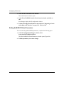
About This Guide
If you are responsible for configuring and managing Bay Networks routers, you
need to read this guide.
This guide describes how to configure and customize your router software for
Internet Protocol (IP) services and for the following IP protocols:
•
Routing Information Protocol (RIP)
•
Open Shortest-Path First (OSPF) Protocol
•
Border Gateway Protocol, Version 3 (BGP-3)
•
Border Gateway Protocol, Version 4 (BGP-4)
•
Exterior Gateway Protocol (EGP)
•
IP Multicasting Protocols
•
NetBIOS over IP
Refer to this guide for
•
An overview of the IP routing protocol and instructions on editing IP global
and interface parameters and configuring basic IP services
•
An overview of RIP, a description of how Bay Networks RIP routing services
work, and instructions on editing RIP parameters and configuring RIP route
filters
•
An overview of OSPF, a description of how Bay Networks OSPF routing
services work, and instructions on editing OSPF parameters and configuring
OSPF route filters
•
An overview of BGP, BGP-3 and BGP-4, a description of how Bay Networks
BGP routing services work, and instructions on editing BGP parameters
•
An overview of EGP, a description of how Bay Networks EGP routing
services work, and instructions on editing EGP parameters
xxiii
Configuring IP Services
•
An overview of IP multicasting services and instructions on editing
multicasting parameters
•
An overview of NetBIOS services, a description of how NetBIOS works over
IP, and instructions for setting NetBIOS over IP parameters
•
An overview of IP accept and announce policies and a description of IP policy
parameters
•
An overview of IP import and export filters and a description of IP import and
export parameters
For information and instructions about the following topics, see Configuring
Routers.
•
Initially configuring and saving an IP interface on which RIP, OSPF, BGP,
and/or EGP are enabled
•
Retrieving a configuration file
•
Rebooting the router with a configuration file
Software Suites
Routing and Switching software is available in the following suites.
xxiv
•
The System Suite includes IP routing, 802.1 Transparent Bridge, Source Route
Bridge, Translation Bridge, SNMP Agent, Bay Networks HDLC, PPP, OSPF,
EGP, BGP, and basic DLSw.
•
The LAN Suite includes DECnet Phase 4, AppleTalk Phase 2, OSI, VINES,
IPX, and ATM DXI, in addition to the System Suite.
•
The WAN Suite includes ATM DXI, Frame Relay, LAPB, and X.25, in
addition to the System Suite.
•
The Corporate Suite includes the System, LAN, and WAN suites in their
entirety.
•
The ARE ATM Suite provides RFC 1483 and 1577 compliance, ATM UNI 3.0
signaling, in addition to the LAN Suite.
•
The ARE VNR Corporate Suite provides ATM Forum LAN Emulation, in
addition to the ARE ATM Suite and Corporate Suite.
About This Guide
•
The BNX Suite includes IP Routing, SNMP Agent, Bay Networks HDLC,
PPP, OSPF, EGP, BGP, File-Based Performance Statistics, Frame Relay
switching, and Frame Relay billing, and selected components from the
Corporate, ARE ATM, and ARE VNR Corporate suites.
Availability of features and functionality described in this guide depends on the
suites you are using.
Audience
This manual is intended for network administrators who configure IP protocols on
Bay Networks routers.
Bay Networks Customer Support
Bay Networks provides live telephone technical support to our distributors,
resellers, and service-contracted customers from two U.S. and three international
support centers. If you have purchased your Bay Networks product from a
distributor or authorized reseller, contact the technical support staff of that
distributor or reseller for assistance with installation, configuration,
troubleshooting, or integration issues.
Customers also have the option of purchasing direct support from Bay Networks
through a variety of service programs. The programs include priority access
telephone support, on-site engineering assistance, software subscription, hardware
replacement, and other programs designed to protect your investment.
To purchase any of these support programs, including PhonePlus™ for 24-hour
telephone technical support, call 1-800-2LANWAN. Outside the U.S. and
Canada, call (408) 764-1000. You can also receive information on support
programs from your local Bay Networks field sales office, or purchase Bay
Networks support directly from your reseller. Bay Networks provides several
methods of receiving support and information on a nonpriority basis through the
following automated systems.
xxv
Configuring IP Services
CompuServe
Bay Networks maintains an active forum on CompuServe. All you need to join us
online is a computer, a modem, and a CompuServe account. We also recommend
using the CompuServe Information Manager software, available from
CompuServe.
The Bay Networks forum contains libraries of technical and product documents
designed to help you manage and troubleshoot your Bay Networks products.
Software agents and patches are available, and the message boards are monitored
by technical staff and can be a source for problem solving and shared experiences.
Customers and resellers holding Bay Networks service contracts can visit the
special libraries to acquire advanced levels of support documentation and
software.
To open an account and receive a local dial-up number, call CompuServe at
1-800-524-3388 and ask for Representative No. 591.
•
In the United Kingdom, call Freephone 0800-289378.
•
In Germany, call 0130-37-32.
•
In Europe (except for the United Kingdom and Germany), call
(44) 272-760681.
•
Outside the U.S., Canada, and Europe, call (614) 529-1349 and ask for
Representative No. 591, or consult your listings for an office near you.
Once you are online, you can reach our forum by typing the command GO
BAYNETWORKS at any ! prompt.
InfoFACTS
InfoFACTS is the Bay Networks free 24-hour fax-on-demand service. This
automated system contains libraries of technical and product documents designed
to help you manage and troubleshoot your Bay Networks products. The system
can return a fax copy to the caller or to a third party within minutes of being
accessed.
xxvi
About This Guide
World Wide Web
The World Wide Web (WWW) is a global information system for file distribution
and online document viewing via the Internet. You need a direct connection to the
Internet and a Web Browser (such as Mosaic or Netscape).
Bay Networks maintains a WWW Home Page that you can access at
http://www.baynetworks.com. One of the menu items on the Home Page is the
Customer Support Web Server, which offers technical documents, software
agents, and an E-mail capability for communicating with our technical support
engineers.
How to Get Help
For additional information or advice, contact the Bay Networks Technical
Response Center in your area:
United States
Valbonne, France
Sydney, Australia
Tokyo, Japan
1-800-2LAN-WAN
(33) 92-966-968
(61) 2-903-5800
(81) 3-328-005
Ordering Bay Networks Publications
To purchase additional copies of this document or other Bay Networks
publications, order by part number from Bay Networks Press™ at the following
numbers. You may also request a free catalog of Bay Networks Press product
publications.
Phone:
FAX - U.S./Canada:
FAX - International:
1-800-845-9523
1-800-582-8000
1-916-939-1010
xxvii
Configuring IP Services
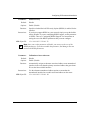
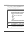
Conventions
angle brackets (< >)
Indicate that you choose the text to enter based on the
description inside the brackets. Do not type the
brackets when entering the command. Example: if
command syntax is ping <ip_address>, you enter
ping 192.32.10.12
arrow character (➔)
Separates menu and option names in instructions.
Example: Protocols➔AppleTalk identifies the
AppleTalk option in the Protocols menu.
brackets ([ ])
Indicate optional elements. You can choose none, one,
or all of the options.
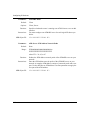
user entry text
Denotes text that you need to enter. Example: Start up
the Windows environment by entering the following
after the prompt: win
command text
Denotes command names in text. Example: Use the
xmodem command.
italic text
Indicates variable values in command syntax
descriptions, new terms, file and directory names, and
book titles.
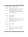
screen text
Indicates data that appears on the screen. Example:
Set Trap Monitor Filters
.
Horizontal (. . .) and vertical ( .. ) ellipsis points
indicate omitted information.
ellipsis points
quotation marks (“ ”)
Indicate the title of a chapter or section within a book.
vertical line (|)
Indicates that you enter only one of the parts of the
command. The vertical line separates choices. Do not
type the vertical line when entering the command.
Example: If the command syntax is
show at routes | nets, you enter either
show at routes or show at nets, but not both.
xxviii
About This Guide
Acronyms
ANSI
American National Standards Institute
ARP
Address Resolution Protocol
ATM
Asynchronous Transfer Mode
BGP
Border Gateway Protocol
CIDR
Classless Interdomain Routing
CMIP
Common Management Information Protocol
DVMRP
Distance Vector Multicast Routing Protocol
EGP
Exterior Gateway Protocol
FDDI
Fiber Distributed Data Interface
IEEE
Institute of Electrical and Electronic Engineers
IGMP
Internet Group Management Protocol
IGP
Interior Gateway Protocol
ILI
intelligent link interface
IS-IS
Intermediate System to Intermediate System
MAC
media access control
MOP
Maintenance Operations Protocol
OSI
Open Systems Interconnection
OSPF
Open Shortest Path First
PVC
permanent virtual circuit
QENET
Quad Ethernet Link Module
RIP
Routing Information Protocol
SMDS
Switched Multimegabit Data Services
SNAP
Subnetwork Access Protocol
SNMP
Simple Network Management Protocol
SRM
system resource modules
SVC
switched virtual circuit
TCP/IP
Transmission Control Protocol/Internet Protocol
TFTP
Trivial File Transfer Protocol
xxix
Chapter 1
IP Concepts, Terminology, and Features
The following sections introduce concepts and terminology used in this manual:
•
IP Router Functions - page 1-1
•
IP Datagrams - page 1-2
•
IP Addresses - page 1-3
•
Autonomous Systems and Routing Protocols - page 1-8
•
Route Preferences - page 1-11
•
Route Weights - page 1-12
•
IP Routing Policies and Filters - page 1-14
•
IP Traffic Filters - page 1-15
•
RFC Compliance - page 1-15
IP Router Functions
An IP (Internet Protocol) router performs three basic functions:
•
Acquires knowledge of other routers and hosts on the network
IP routers use routing protocols — for example, OSPF and BGP — to learn
transmission paths (or routes) to other networks and to hosts residing on
networks directly connected to the router.
•
Stores network topology information about transmission paths in routing
tables
•
Selects the best path, based on the information in its routing tables, for a
particular datagram (a self-contained unit of data) to reach its destination
1-1
Configuring IP Services
IP routers process each datagram individually. The datagram header provides
the router with the destination IP address, as well as other routing
information. Routers select a transmission path based on the IP address of the
destination network, not of the destination host.
IP Datagrams
An IP datagram is the unit of data exchanged between IP modules. In addition to
data, a datagram includes a header with fields that provide the following
information used by IP routers:
•
Type of Service
This field indicates the quality of service the datagram requires. The IP router
inspects the Type of Service field to obtain information about the datagram’s
precedence and expected delay characteristics.
•
Time to Live
This field determines the datagram’s lifetime in the Internet system. Each time
an IP router processes the datagram header, it decrements the value in the
Time to Live field by at least one hop. When the value reaches zero, the IP
router discards the datagram, unless it is destined for the router itself, thus
preventing undeliverable datagrams from looping endlessly through the
network, consuming Internet resources.
•
Options
This field may or may not be present in a datagram; therefore, IP datagrams
vary in length. There are three classes of options:
— Security, which specifies security level and distribution restrictions
— Timestamps, which is a 32-bit value measured in milliseconds since
midnight universal time, or any other value if the high-order bit is set to 1
— Special Routing, which specifies host-discovered paths to other hosts, or a
specific path for the datagram to take
•
Header Checksum
This field contains a value that the IP router calculates each time it processes a
datagram’s IP header. The algorithm used to calculate the checksum value is a
16-bit ones complement addition of the 16-bit words contained only within
the IP header. The IP router discards datagrams received with an incorrect IP
header checksum.
1-2
IP Concepts, Terminology, and Features
IP Addresses
An IP address consists of 32 bits that have the form network.host. The network
portion is a network number ranging from 8 to 24 bits. The host portion is the
remaining 8 to 24 bits identifying a specific host on the network. The Internet
Network Information Center (NIC) assigns the network portion of the IP address.
Your network administrator assigns the host portion.
NIC recognizes three primary classes of networks: A, B, and C. In addition, NIC
has recently identified two other classes: Class D for networks that support
multicasting, which allows an IP datagram to be transmitted to a single multicast
group consisting of hosts spread across separate physical networks; and Class E
for experimental networks. The IP router does not fully support Class D or Class
E networks.
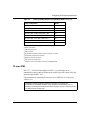
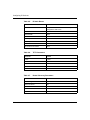
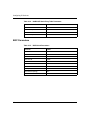
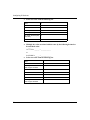
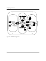
Based on the size of the network, the NIC classifies a network as Class A, B, or C
(the most common). The network class determines the number of bits assigned to
the network and host portions of the IP address, as follows:
Network Size
Class
Network Portion
Host Portion
More than 65,534 hosts
A
8 bits
24 bits
254 to 65,533 hosts
B
16 bits
16 bits
Fewer than 254 hosts
C
24 bits
8 bits
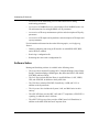
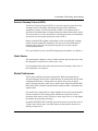
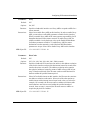
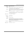
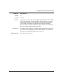
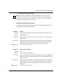
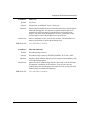
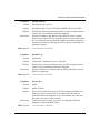
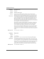
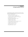
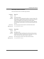
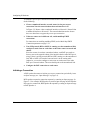
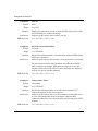
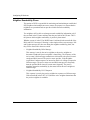
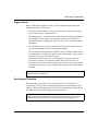
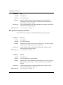
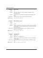
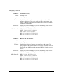
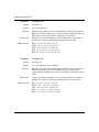
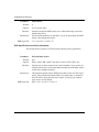
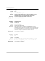
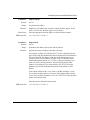
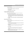
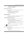
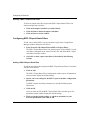
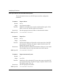
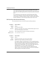
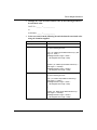
The position of the first bit set to 0 (whether it is the first, second, third, or fourth
bit) in the first octet of an IP address indicates the network class (A, B, C, or D). If
no bit is set to 0, it is a Class E network.
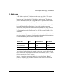
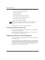
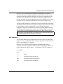
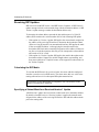
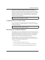
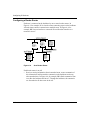
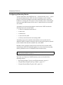
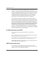
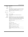
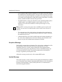
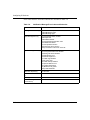
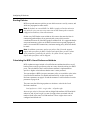
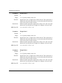
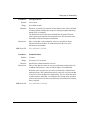
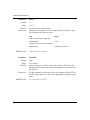
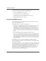
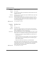
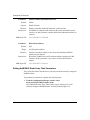
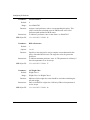
Figure 1-1 shows the placement of the first bit set to 0 for Class A, B, and C
networks. The figure also shows how a network’s class affects the network and
host portions of the IP address.
1-3
Configuring IP Services
Class A
8
16
24
31
8
16
24
31
8
16
24
31
0
Class B
11 0
Class C
11 11 0
First Octet
Range
Example
Network
Host
Class A
0
1-127
25.0.0.1
25
1
Class B
11 0
128-191
140.250.0.1
140.250
1
Class C
11 11 0
192-223
192.2.3.1
192.2.3
1
Network Portion
Figure 1-1.
Host Portion
Network and Host Portions of IP Addresses
You specify IP addresses in dotted decimal notation. To express an IP address in
dotted decimal notation, you convert each 8-bit octet of the IP address to a
decimal number and separate the numbers by decimal points.
For example, you specify the 32-bit IP address 10000000 00100000 00001010
10100111 in dotted decimal notation as 128.32.10.167. The most significant 2 bits
(10) in the first octet indicate that the network is Class B; therefore, the first 16
bits compose the NIC-assigned network portion field. The third octet (00001010)
and fourth octet (10100111) compose the host field.
Subnet Addressing
The concept of subnetworks (or subnets) extends the IP addressing scheme.
Subnets are two or more physical networks that share a common networkidentification field (the NIC-assigned network portion of the 32-bit IP address).
Subnets allow an IP router to hide the complexity of multiple LANs from the rest
of the internet.
1-4
IP Concepts, Terminology, and Features
With subnets, you partition the host portion of an IP address into a subnet number
and a “real” host number on that subnet. The IP address is then defined by
network.subnet.host. Routers outside the network do not interpret the subnet and
host portions of the IP address separately.
Routers inside a network containing subnets use a 32-bit subnet mask that
identifies the extension bits. In network.subnet.host, the subnet.host portion (or
the local portion) contains an arbitrary number of bits. The network administrator
allocates bits within the local portion to subnet and host, and then assigns values
to subnet and host.
For example, the following is the IP address of a network that contains subnets:
10000000 00100000 00001010 10100111. You specify this address in dotted
decimal notation as 128.32.10.167.
The second bit of the first octet is set to 0, indicating that the network is a Class B
network. Therefore, the NIC-assigned network portion contains 16 bits, and the
locally assigned local portion contains 16 bits.
The network administrator allocates the 16 bits in the local portion field as
follows:
•
Allocates the upper 8 bits (00001010) with a value of 10 to the subnet portion
•
Allocates the lower 8 bits (10100111) with a value of 167 to the host portion
In other words, the 16-bit local portion field, together with the 16-bit network
field, specify host 167 on Subnet 10 of network 128.32.
You now need a subnet mask to identify those bits in the 32-bit IP address that
specify the network field and those bits that specify the subnet field. Like the IP
address, you specify the subnet mask in dotted decimal notation.
You construct a subnet mask as follows:
•
Assign a value of 1 to each of the 8, 16, or 24 bits in the network field.
•
Assign a value of 1 to each bit in the subnet field.
•
Assign a value of 0 to each bit in the host field.
•
Convert the resulting 32-bit string to dotted decimal notation.
1-5
Configuring IP Services
For example, to construct a subnet mask for the IP address described earlier
(10000000 00100000 00001010 10100111), do the following:
1. Assign a value of 1 to each bit in the network field.
The position of the first bit set to 0 in the first octet of the IP address indicates
that the network is Class B; therefore, the network field contains 16 bits:
11111111 11111111.
2. Assign a value of 1 to each bit in the subnet field.
The network administrator allocated the upper 8 bits of the local portion to the
subnet portion, as follows: 11111111.
3. Assign a value of 0 to each bit in the host field.
The network administrator allocated the lower 8 bits of the local portion field
to the host identification, as follows: 00000000.
4. Convert the resulting 32-bit string (11111111 11111111 11111111 00000000)
to dotted decimal notation, as follows: 255.255.255.000.
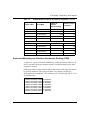
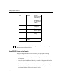
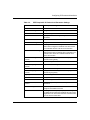
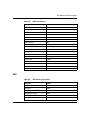
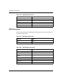
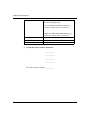
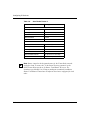
Table 1-1 shows the range of possible subnet masks for Class B and Class C
addresses, along with the number of bits that the mask allocates for a subnet
address, the number of recommended subnets associated with the mask, and the
number of hosts per subnet.
Table 1-1.
Subnet Masks for Class B and Class C Addresses
Number of Bits
Subnet Mask
Number of
Subnets
(Recommended)
Number of Hosts
per Subnet
Class B
2
255.255.192.0
2
16,382
3
255.255.224.0
6
8,190
4
255.255.240.0
14
4,094
5
255.255.248.0
30
2,046
6
255.255.252.0
62
1,022
7
255.255.254.0
126
510
8
255.255.255.0
254
254
9
255.255.255.128
510
126
(continued)
1-6
IP Concepts, Terminology, and Features
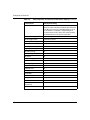
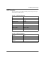
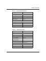
Table 1-1.
Subnet Masks for Class B and Class C Addresses (continued)
Number of
Subnets
(Recommended)
Number of Hosts
per Subnet
Number of Bits
Subnet Mask
10
255.255.255.192
1,022
62
11
255.255.255.224
2,046
30
12
255.255.255.240
4,094
14
13
255.255.255.248
8,190
6
14
255.255.255.252
16,382
2
2
255.255.255.192
2
62
3
255.255.255.224
6
30
4
255.255.255.240
14
14
5
255.255.255.248
30
6
6
255.255.255.252
62
2
Class C
Supernet Addressing and Classless Interdomain Routing (CIDR)
A supernet is a group of networks identified by contiguous network addresses. IP
service providers can assign customers blocks of contiguous addresses to define
supernets as needed.
Each supernet has a unique supernet address that consists of the upper bits shared
by all of the addresses in the contiguous block. For example, consider the
following block of contiguous 32-bit addresses (192.32.0.0 through 192.32.7.0 in
decimal notation).
11000000 00100000 00000000 00000000
11000000 00100000 00000001 00000000
11000000 00100000 00000010 00000000
11000000 00100000 00000011 00000000
11000000 00100000 00000100 00000000
11000000 00100000 00000101 00000000
11000000 00100000 00000110 00000000
11000000 00100000 00000111 00000000
1-7
Configuring IP Services
The supernet address for this block is 11000000 00100000 00000, the 21 upper
bits shared by the 32-bit addresses.
A complete supernet address consists of an address/mask pair:
•
address is the first 32-bit IP address in the contiguous block. In this example,
the address is 11000000 00100000 00000000 00000000 (192.32.0.0 in
decimal notation).
•
mask is a 32-bit string containing a set bit for each bit position in the supernet
part of the address. The mask for the supernet address in this example is
11111111 11111111 11111000 00000000 (255.255.248.0 in dotted decimal
notation).
The complete supernet address in this example is 192.32.0.0/255.255.248.0.
Classless interdomain routing (CIDR) is an addressing scheme that employs
supernet addresses to represent multiple IP destinations. Rather than advertise a
separate route for each destination in a supernet, a router can use a supernet
address to advertise a single route — called an aggregate route — that represents
all of the destinations. This reduces the size of the routing tables used to store
advertised IP routes.
BGP-4 supports classless interdomain routing. OSPF supports classless routing
within a domain.
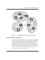
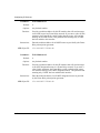
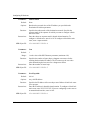
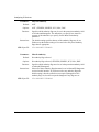
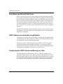
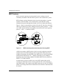
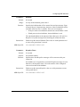
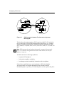
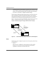
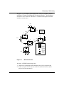
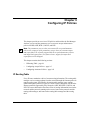
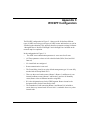
Autonomous Systems and Routing Protocols
LANs and WANs interconnected by IP routers form a group of networks called an
internet. For administrative purposes, an internet is divided into autonomous
systems. An autonomous system (AS) is simply a collection of routers (called
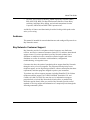
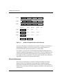
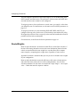
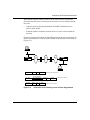
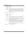
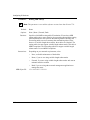
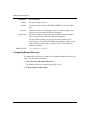
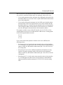
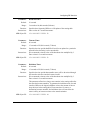
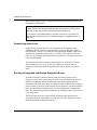
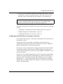
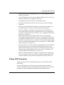
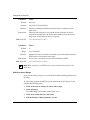
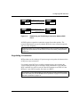
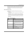
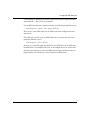
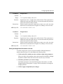
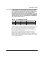
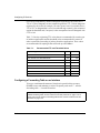
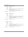
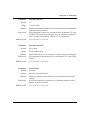
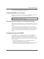
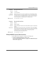
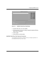
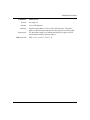
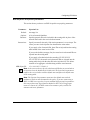
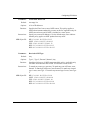
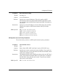
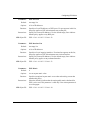
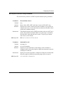
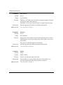
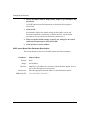
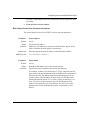
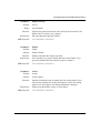
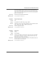
gateways in IP terminology) and hosts. Figure 1-2 depicts a sample internet
segmented into three autonomous systems.
Routers inside an autonomous system use an interior gateway protocol to
communicate network topology changes to each other. Routers in separate
autonomous systems use an exterior gateway protocol to communicate. The IP
router implements two dynamic interior protocols: RIP and OSPF. The IP router
implements two exterior protocols: BGP and EGP.
1-8
IP Concepts, Terminology, and Features
Router
2
LAN
A
Autonomous
System 1
Router
1
LAN
B
Router
4
Router
3
Router
5
LAN
C
Autonomous
System 3
Autonomous
System 2
LAN
F
Figure 1-2.
Router
8
LAN
D
Router
7
LAN
G
Router
9
Router
6
LAN
E
Internet Segmented into Three Autonomous Systems
Routing Information Protocol (RIP)
The Routing Information Protocol (RIP) is a distance-vector protocol that enables
routers in the same autonomous system to exchange routing information by means
of periodic RIP updates. Routers transmit their own RIP updates to neighboring
networks and listen for RIP updates from the routers on those neighboring
networks. Routers use the information in the RIP updates to keep their internal
routing tables current. For RIP, the “best” path to a destination is the shortest path
(the path with the fewest hops). RIP computes distance as a metric, usually the
number of hops (or routers) from the origin network to the target network.
For RIP configuration information, see Chapter 3.
1-9
Configuring IP Services
Open Shortest Path First (OSPF) Protocol
The Open Shortest Path First (OSPF) protocol is an IGP intended for use in large
networks. Using a link state algorithm, OSPF exchanges routing information
between routers in an autonomous system. Routers synchronize their topological
databases. Once the routers are synchronized and the routing tables are built, the
routers will flood topology information only in response to some topological
change. For OSPF, the “best” path to a destination is the path that offers the least
cost metric delay. In OSPF, cost metrics are configurable, allowing you to specify
preferred paths.
OSPF supports CIDR and can carry supernet advertisements within a routing
domain.
For a more detailed overview and OSPF configuration information, see Chapter 4.
Border Gateway Protocol (BGP)
The Border Gateway Protocol (BGP) is an exterior gateway protocol used to
exchange network reachability information with other BGP systems. BGP routers
form relationships with other BGP routers. Using an entity called a BGP speaker,
BGP routers transmit and receive current routing information over a reliable
transport layer connection. Because a reliable transport mechanism is used,
periodic updates are not necessary.
BGP updates contain “path attributes” that describe the route to a set of
destination networks. When multiple paths are available, BGP compares these
path attributes to choose the preferred path.
BGP-3 and BGP-4 are supported. BGP-4 is the border gateway protocol that
supports CIDR.
For a more detailed overview and BGP configuration information, see Chapter 5.
1-10
IP Concepts, Terminology, and Features
Exterior Gateway Protocol (EGP)
The Exterior Gateway Protocol (EGP-2) is an exterior gateway protocol used to
exchange network reachability information between routers in different
autonomous systems. An IGP, such as RIP or OSPF, is used within an AS to
facilitate the communication of routing information with the autonomous system.
The routers that serve as the end points of a connection between two autonomous
systems run an exterior gateway protocol, such as EGP-2.
Routers establish EGP neighbor relationships in order to periodically exchange
reliable network reachability information. The router uses this information to
maintain a list of gateways, the networks the gateways can reach, and the
corresponding distances.
For a more detailed overview and EGP configuration information, see Chapter 6.
Static Routes
You can manually configure a route to another network and enter the route in the
IP routing table. Such a route is called a static route.
For information about static routes and instructions on including a static route in
the routing table, see Chapter 2.
Route Preferences
The IP router maintains an internal routing table. When determining how to
forward a datagram, the IP router consults the table to determine the specific route
a datagram should take. A routing table can contain direct routes for the IP
router’s network interfaces, static routes, and the routes learned from RIP, OSPF,
BGP, and/or EGP, if enabled (information about adjacent hosts is maintained in a
separate table).
It is possible for a routing table to contain multiple routes to the same destination.
In such a situation, IP uses (among other information) a preference value to
determine which route to select. Preference values range from 1 to 16 (the higher
the number, the greater the preference).
By default, RIP, BGP, EGP, and OSPF external routes have a preference value of
1. Static routes, direct routes, and OSPF intra-area and interarea routes have a
default preference of 16.
1-11
Configuring IP Services
You can configure a preference value in the range of 1 to 16 for RIP, BGP, EGP,
OSFP external, and static routes. The preference of direct routes and OSPF intraarea and interarea routes cannot be user-configured.
To assign a greater or lesser preference to a static route, you supply a value when
you define the route. For instructions, see the static route Preference parameter on
page 2-67.
To assign a preference to a route learned by RIP, OSPF, BGP, and EGP, you
configure an accept policy for the route. If an incoming route matches the policy,
IP assigns the preference value you specify to the route and considers the route for
possible inclusion in the routing table.
For instructions, see the Route Preference parameter on page 9-9.
Route Weights
Route-weight calculation is an internal tool that IP uses to facilitate selection of
the best route among alternative routes to the same destination. Route-selection
criteria are encoded into the route weight in a way that allows IP to compare
routes simply by comparing their weight values, regardless of route sources.
Appendix B contains a worksheet that you can you use to calculate route weights
in your configuration.
Route-weight calculation increases the efficiency of the route-selection process
and at the same time reduces the size of the routing database, since all route
selection parameters for each route are encoded in a single integer — the weight
value — rather than stored in separate variables.
1-12
IP Concepts, Terminology, and Features
Using selection criteria encoded in the route weight, IP chooses routes in the
following order:
•
The route with the highest preference value (see “Route Preferences” on
page 1-11)
•
A direct or OSPF intra-area route with the lowest metric
Note: Beginning with Version 8.00, a direct route (interface) that is part of an
OSPF area is not automatically chosen over an OSPF intra-area route. As a
result, it is possible to configure a slow direct link (for example, a backup
dialup line) with a high metric value (wfIpInterfaceCost) and route packets to
a fast link on another router in the same OSPF area. Direct routes that are not
included in an OSPF area are assumed to have a metric of 0 and are always
chosen over other routes.
•
A direct route with the lowest metric
•
An OSPF intra-area route with the lowest metric
•
An OSPF interarea route with the lowest metric
•
An OSPF Type 1 external route with the lowest metric
•
A BGP route with the highest LOCAL_PREF value
•
A RIP route with the lowest metric
•
An EGP route with the lowest metric
•
A static route with the lowest metric
•
An OSPF Type 2 external route with a pre-Version-8.00-style metric
Note: If OSPF is configured to propagate external routes using the route
weight as the Type 2 metric, routes that are received as OSPF ASE Type 2
routes are evaluated according to their respective origins (for example, RIP or
BGP).
1-13
Configuring IP Services
IP Routing Policies and Filters
The IP router allows you to control the flow of routing data to and from the
routing tables. This control is provided by two mechanisms:
•
IP accept and announce policies
•
Import and export filters
Note: Accept and announce policies provide a superset of the parameters
provided by import and export filters. We currently support both IP policies
and IP route filters. However, network administrators using import and export
filters for routing table management should migrate as quickly as possible to
IP policies. In a future release, support for import and export filters will be
discontinued.
IP accept policies (and the subset of parameters provided by import filters) govern
the addition of new RIP-, OSPF-, BGP-, or EGP-derived routes to the routing
tables. When RIP, OSPF, BGP, or EGP receives a new routing update, it consults
its accept policies to validate the information before entering the update into the
routing tables. Accept policies contain search information (to match fields in
incoming routing updates) and action information (to specify the action to take
with matching routes).
IP announce policies (and the subset of parameters provided by export filters)
govern the propagation of RIP, OSPF, BGP, or EGP routing information. When
preparing a routing advertisement, RIP, OSPF, BGP, or EGP consults its announce
policies to determine whether the routes to specific networks are to be advertised
and how they are to be propagated. Announce policies contain network numbers
(to associate a policy with a specific network) and action information (to specify a
route propagation procedure).
IP accept and announce policies and policy parameters are described in Chapter 9.
IP import and export filters and filter parameters are described in Chapter 10.
1-14
IP Concepts, Terminology, and Features
IP Traffic Filters
A traffic filter enables the router to selectively relay or drop an inbound packet,
frame, or datagram based on standard protocol fields or user-defined fields. Traffic
filters apply to incoming traffic only.
For information on IP traffic filters, see Configuring Traffic Filters and Protocol
Prioritization.
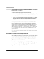
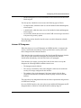
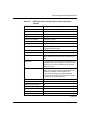
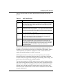
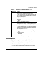
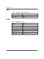
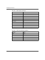
RFC Compliance
Table 1-2 lists the Internet Requests for Comments (RFCs) with which the IP
router complies. This manual assumes you are familiar with these RFCs.
Table 1-2.
IP Router RFC Support
RFC
Specifies
768
User Datagram Protocol (UDP)
783
Trivial File Transfer Protocol (TFTP)
791
Internet Protocol (IP)
792
Internet Control Message Protocol (ICMP)
826
Address Resolution Protocol (ARP)
950
Internet subnetting procedures
1009
Internet gateways
1058
Routing Information Protocol (RIP)
1063
Maximum Transmission Unit (MTU) discovery option
1583
Open Shortest Path First (OSPF) Protocol Version 2
1157
Simple Network Management Protocol (SNMP)
1188
IP over FDDI networks
1042
IP over IEEE 802.x networks
1027
Proxy ARP
1112
Host Extensions for IP Multicasting
1256
ICMP Router Discovery Messages
1267
BGP-3
1403
BGP OSPF Interaction
1654
BGP-4
1-15
Chapter 2
Configuring IP Routers and Interfaces
This chapter consists of the following sections:
•
Configuring IP Interfaces - page 2-2
•
Configuring IP on a Router Slot - page 2-6
•
Specifying a Broadcast Address - page 2-7
•
Configuring a MAC Address for an Adjacent Host - page 2-8
•
Selecting an Address Resolution Protocol - page 2-8
•
Enabling Source Routing over Token Ring Networks - page 2-12
•
Configuring the Trivial File Transfer Protocol - page 2-14
•
Defining a Circuitless IP Interface - page 2-15
•
Configuring the Revised IP Security Option - page 2-16
•
Defining a Static Route - page 2-22
•
Defining a Black Hole for a Supernet - page 2-22
•
Configuring Router Discovery - page 2-23
•
Specifying the Size of IP Forwarding Tables - page 2-23
•
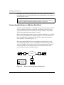
Connecting the Router to a Blacker Front End - page 2-24
•
Configuring Host-Only Mode - page 2-30
•
IP over ATM - page 2-29
•
Editing IP Parameters - page 2-31
2-1
Configuring IP Services
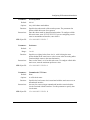
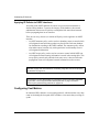
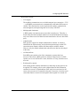
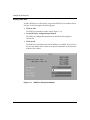
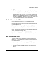
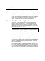
Configuring IP Interfaces
An IP network interface consists of a physical circuit configured with the
appropriate data link and IP protocols. Each interface connects the router to one or
more IP networks.
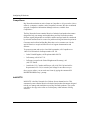
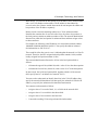
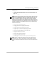
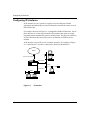
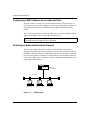
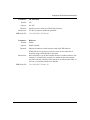
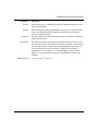
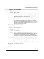
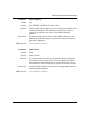
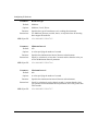
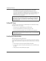
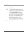
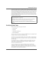
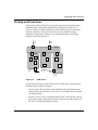
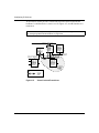
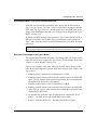
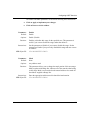
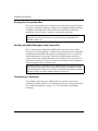
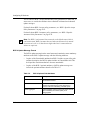
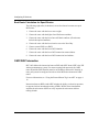
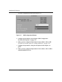
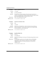
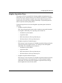
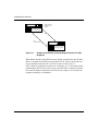
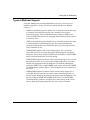
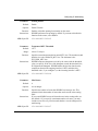
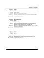
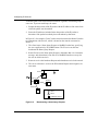
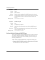
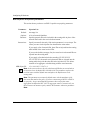
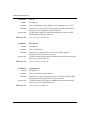
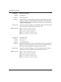
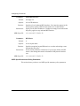
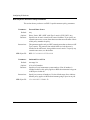
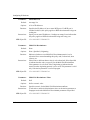
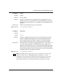
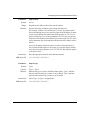
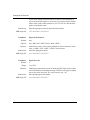
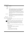
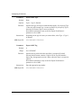
For example, the router in Figure 2-1 is configured with three IP interfaces. One of
these interfaces is a point-to-point interface that connects the router to a single
long-haul medium terminated by a host or another router. The other two interfaces
are LAN interfaces that connect the router to an Ethernet or FDDI local area
medium.
An IP interface can provide access to multiple networks. For example, in Figure
2-1, LAN interface 1 provides a connection to both LAN B and LAN C.
WAN A
LAN B
Host
D
Point-to-Point Interface
Host
C
LAN Interface 1
Router
LAN C
LAN Interface 2
LAN A
Host
A
Figure 2-1.
2-2
Host
B
IP Interface
Host
E
Configuring IP Routers and Interfaces
As part of the router configuration process, the network administrator associates a
network with an interface by assigning the network’s unique IP address to the
circuit on which the interface is configured.
For instructions on using Site Manager to configure an IP interface, see “Configuring a
Circuit and Adding an IP Interface” on page 2-32 and “Editing IP Interface Parameters” on
page 2-35.
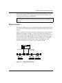
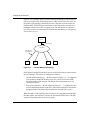
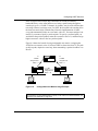
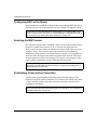
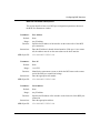
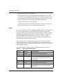
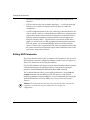
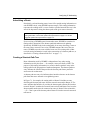
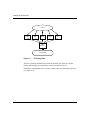
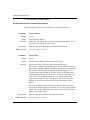
Multinet Interfaces
The multinet capability allows you to assign multiple IP network/subnet addresses
to a single circuit; each IP address represents a separate network interface on the
circuit.
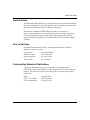
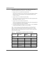
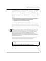
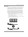
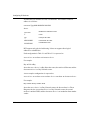
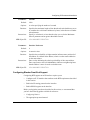
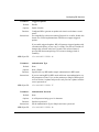
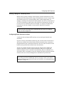
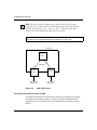
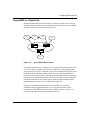
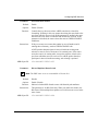
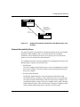
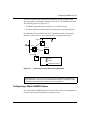
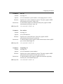
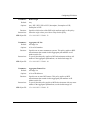
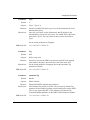
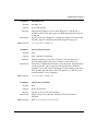
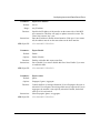
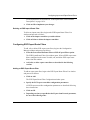
Multinet is commonly used in IP networks containing hosts that do not understand
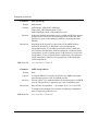
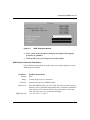
subnetting. For example, in Figure 2-2, Hosts A, B, and C are connected by a
router. Because the hosts do not understand subnetting, A, B, and C operate as if
they are all on the same network. While A and C are on the same network, B is
not. To facilitate connectivity between the three hosts, the router is configured
with interfaces that connect three distinct subnets, as defined by the mask
255.255.255.0. In Figure 2-2, A and C are on a multinet interface.
Router
e21
140.250.150.0
Host
B
140.250.150.2
Figure 2-2.
e22
140.250.200.0
140.250.250.0
Host
A
140.250.200.56
Host
C
140.250.250.3
Multinet Configuration
2-3
Configuring IP Services
Adding an Unnumbered IP Interface to a Point-to-Point Circuit
IP allows you to configure an interface on a point-to-point connection without
using an IP address. Such an interface is called an unnumbered interface. Point-topoint connections using unnumbered interfaces can be configured to advertise RIP
(see Note), OSPF, IBGP, DVMRP, and static routes.
For instructions on using Site Manager to add an unnumbered IP interface to a circuit,
see “Configuring a Circuit and Adding an IP Interface” on page 2-32.
The ability to establish a point-to-point link using an unnumbered IP interface
helps alleviate two of the major problems caused by the continued rapid growth of
the Internet: exhaustion of Class B network addresses and exhaustion of the 32-bit
IP address space.
The network administrator associates each unnumbered interface with the IP
address of any numbered interface on the router, including the circuitless
interface. The router can support multiple unnumbered interfaces. Multiple
unnumbered interfaces can be associated with the same IP address.
Since all traffic over an unnumbered interface uses broadcast addressing at the
link layer, neither an adjacent host specification or address resolution is required.
Note: The associated address assigned to the unnumbered interface
determines whether or not RIP configured to send updates in V1 mode will
advertise a subnetwork over the unnumbered interface. The associated address
also determines which mask is applied to RIP V1 updates received on that
interface. For unnumbered links using RIP V1, the defined associated
addresses at each end of the link must belong to the same network and have
the same mask for routes to be exchanged correctly.
If a subnetwork on the router has the same mask as the associated address,
RIP V1 will advertise that subnet over the unnumbered interface. If the mask
on the subnetwork is different from the mask of the associated address, RIP V1
advertises only the natural network of the subnet.
We recommend that you select RIP2 mode for unnumbered interfaces. With
RIP2, RIP updates contain both the route and mask information.
2-4
Configuring IP Routers and Interfaces
Note: BGP peers, NetBIOS, and BOOTP cannot be configured directly on an
unnumbered interface.
For information on using Site Manager to configure a BGP peer-to-peer
session on routers connected through unnumbered interfaces, see
“Configuring BGP Peers over an Unnumbered Point-to-Point Link” on page
5-5.
To route NetBIOS packets over an unnumbered interface, you must configure a
static entry to the Name Server. For complete information, see “Forwarding
Name Query Packets over an Unnumbered IP Interface” on page 8-3.
To run BOOTP over unnumbered interfaces, you must select a preferred
BOOTP server. For instructions, see Configuring SNMP, BOOTP, DHCP, and
RARP Services.
Note: Unnumbered interfaces cannot be pinged directly. For this reason, such
interfaces can add to the difficulty of diagnosing router problems.
Storing Unnumbered Routes in the Routing Table
As it does with routes learned over numbered interfaces, IP stores each route
learned over an unnumbered interface in the routing table.
The routing-table entry for a route learned over an unnumbered interface contains
the following values:
Next-hop address
0
Next-hop mask equals
0
Next-hop interface
Circuit number of the unnumbered interface
2-5
Configuring IP Services
Using the Alternate Associated Address Option
The alternate associated address option ensures that a network on an unnumbered
interface remains reachable. In the event that an associated address becomes
invalid, IP switches to a usable address (if one is available).
Note: In the event that an unnumbered associated address becomes
unreachable, some functionality may be lost for certain protocols over the
unnumbered interface.
Note: In some configurations, changing the associated address can affect the
way routes are advertised. In a RIP configuration, for example, if you change
the associated address for an unnumbered interface configured with RIP, you
may change the way RIP advertises subnets.
For instructions on using Site Manager to select the alternate unnumbered associated
address option, see the UnNumbered Assoc Alternate parameter on page 2-49.
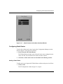
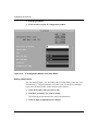
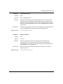
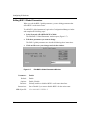
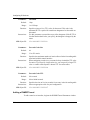
Configuring IP on a Router Slot
IP runs on all slots that contain IP interfaces.When you add an IP interface to a
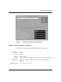
circuit, Site Manager enables IP on the slot.
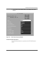
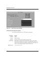
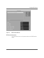
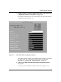
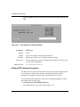
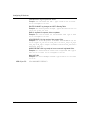
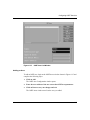
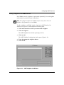
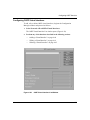
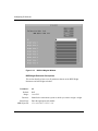
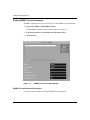
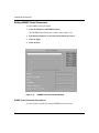
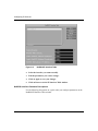
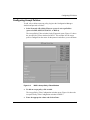
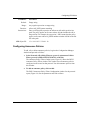
By default, IP runs with certain characteristics and services enabled. You can
accept these default characteristics or use the IP Global Parameters window (see
Figure 2-12) to customize IP — to enable and disable IP on the router, specify
whether the router forwards IP traffic to other routers, and supply aging, time-tolive, and other values. IP global parameters also allow you to help IP software
preallocate system resources by providing the router with an estimate of the
number of networks and hosts the router will be required to support.
When you set parameters on the IP Global Parameters window, you are affecting
the way IP operates on all slots where it is configured.
For instructions on using Site Manager to configure and customize IP services on the
router, see “Configuring a Circuit and Adding an IP Interface” on page 2-32.
2-6
Configuring IP Routers and Interfaces
Specifying a Broadcast Address
Broadcasting occurs when the IP router transmits a single packet to every host on
an attached network. To do so, it uses a broadcast address that refers to all hosts on
the network. A broadcast address is simply an IP address that contains all 1s or all
0s in the host portion.
For example, if you have an IP network with IP address 10.3.45.12, you can
configure a broadcast address for that network, as follows:
•
Because the address is for a Class A network (the network portion is 1 byte),
the host portion contains 3 bytes.
•
Because the host portion of a broadcast address consists of all 1s or all 0s, the
broadcast address for that network can be one of the following:
10.255.255.255, 10.0.0.0, 255.255.255.255, or 0.0.0.0.
Some networks do not support broadcasts; thus, configuring an IP broadcast
address does not guarantee efficient broadcast delivery.
For instructions on using Site Manager to configure a broadcast address on an IP
interface, see the Broadcast Address parameter on page 2-38.
Subnet Broadcast Addresses
The way you configure a broadcast address for a subnet is different from the way
you configure a broadcast address for a network. Because you extend the network
portion of the IP address when you create subnets, you automatically take away
from the host portion of the IP address. To configure a subnet broadcast, you take
the subnet mask for that subnet and invert it. For example, if the IP address of the
subnet is 10.4.2.3, and the mask is 255.255.0.0, then the subnet broadcast address
is either 10.4.255.255 or 10.4.0.0.
IP permits an all-zero subnet address but discourages its use for the following
reason. If an all-zero subnet address and an all-zero broadcast address are both
valid, the router cannot distinguish an all-subnets broadcast from a directed
broadcast for the zero subnet.
For information on using Site Manager to allow the use of an all-zero subnet address, see
the Zero Subnet Enable parameter on page 2-59.
2-7
Configuring IP Services
Configuring a MAC Address for an Adjacent Host
An adjacent host is a device on a locally attached network. This device may or
may not be a router. You must configure a media access control (MAC) address for
each adjacent host that does not implement the Address Resolution Protocol
(ARP).
Also, if a local network does implement ARP, you may want to configure a MAC
address for an adjacent host to pre-empt the ARP process.
For instructions on using Site Manager to configure a connection to an adjacent host, see
“Configuring a Path to an Adjacent Host” on page 2-68.
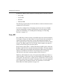
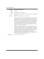
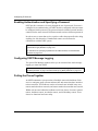
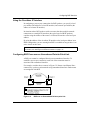
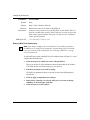
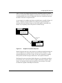
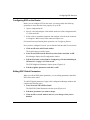
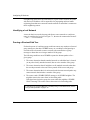
Selecting an Address Resolution Protocol
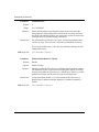
The IP router needs both a physical address and an IP address to transmit a
datagram. In situations where the router knows only the network host’s IP address,
the Address Resolution Protocol (ARP) enables the router to determine a network
host’s physical address by binding a 32-bit IP address to a 48-bit MAC address. A
router can use ARP across a single network only, and the network hardware must
support physical broadcasts.
Router
140.250.200.1
00 00 A2 00 00 01
140.250.200.0
Host
A
Host
B
Host
C
140.250.200.2
00 00 A2 00 10 20
140.250.200.3
00 00 A2 00 10 30
140.250.200.4
00 00 A2 00 10 40
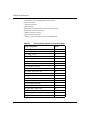
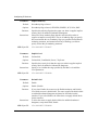
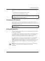
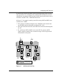
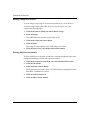
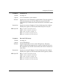
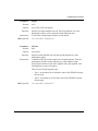
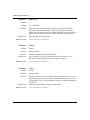
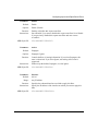
Figure 2-3.
2-8
ARP Example
Configuring IP Routers and Interfaces
For example, in Figure 2-3, the router and Host C are on the same physical
network. Both devices have an assigned IP address (the router’s is 140.250.200.1
and Host C’s is 140.250.200.4) and both devices have an assigned physical
address (the router’s is 00 00 A2 00 00 01 and Host C’s is 00 00 A2 00 10 40).
In Figure 2-3, the router wants to send a packet to Host C but knows only Host C’s
IP address. The router uses ARP to determine Host C’s physical address, as
follows:
1. The router broadcasts a special packet, called an ARP request, that asks IP
address 140.250.200.4 to respond with its physical address.
2. All network hosts receive the broadcast request.
3. Only Host C responds with its hardware address.
The router maps Host C’s IP address (140.250.200.4) to its physical address
(00 00 A2 00 10 40) and saves the results in an address-resolution cache for future
use.
Note: It is possible for the router to send out ARP requests even if ARP, which
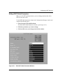
is a dynamically loaded module, is not currently loaded on the router. It is the
responsibility of the network administrator to ensure that ARP is loaded
correctly on a slot. To do this through Site Manager, select Events
Manager➔Options➔Filters; then select LOADER and Debug, and do a
File➔Get Current Log File. Verify that ARP is loaded on a slot by locating the
following message in the log:
#xx:01/01/95 10:10:55.00 DEBUG SLOT x LOADER CODE:33
Loader service completed for ARP.EXE 0xxxxxxxxx
Site Manager allows you to select an address-resolution protocol for an IP interface. For
instructions, see the Address Resolution parameter on page 2-40. Site Manager also
allows you to select an ARP type for an interface configured for a Token Ring network. For
instructions, see the TR Endstation ARP Type parameter on page 2-51.
2-9
Configuring IP Services
In addition to ARP, IP routers support the following address-resolution schemes:
•
Proxy ARP
•
Inverse ARP
•
HP Probe
•
DDN and PDN
The following sections briefly describe the address-resolution schemes that can be
configured on an IP interface.
On interfaces configured for a Token Ring network, the router can send ARP
requests as spanning tree explorer (STE) packets or all route explorer (ARE)
packets. For information, see “Enabling Source Routing over Token Ring
Networks” on page 2-12.
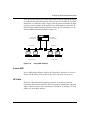
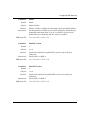
Proxy ARP
Proxy ARP allows a router to answer a local ARP request for a remote destination.
For example, in Figure 2-4, Hosts B and C are located on the same network but on
separate subnetworks. Hosts B and C do not understand subnetworking. The
router connecting the two physical networks knows which host resides on which
network. The address mask is 255.255.255.000. In this example, one subnet is a
remote network with respect to the other subnet.
Host B wants to talk to Host C, so Host B broadcasts an ARP request, which asks
IP address 140.250.250.2 to respond with its physical address. The router captures
Host B’s ARP request and responds with its hardware address 00 00 A2 00 00 01
and Host C’s IP address 140.250.250.2. Host B maps Host C’s IP address
140.250.250.2 to the router’s hardware address 00 00 A2 00 00 01.
With Proxy ARP enabled, the router will respond with an ARP reply if there is a
valid route (that is, if the router is able to forward traffic) to the destination in the
routing table. This route may be a subnet route or a default route. For the router to
respond for subnets that are reachable via the default route, you must configure IP
to use a default route for unknown subnets. For instructions, see the Enable
Default Route for Subnets parameter on page 2-60.
2-10
Configuring IP Routers and Interfaces
There are devices that use Proxy ARP to determine a gateway rather than relying
on a statically defined default gateway. These devices will use ARP for all remote
destinations. To enable the router to reply to ARP for remote destinations on other
networks, you must enable the IP Interface Proxy ARP parameter and set the IP
Global Nonlocal ARP Destination parameter to Accept. For instructions, see the
Nonlocal ARP Destination parameter on page 2-56.
140.250.200.1
00 00 A2 00 00 01
140.250.250.1
00 00 A2 00 00 02
Router
140.250.200.0
Host
A
Host
B
140.250.200.2
140.250.200.3
140.250.250.0
Host
C
140.250.250.2
00 00 A2 00 10 30
Figure 2-4.
Host
D
140.250.250.3
00 00 A2 00 10 6
Proxy ARP Example
Inverse ARP
Inverse ARP enables address resolution for Frame Relay interfaces. It is used to
discover the IP address of the station at the remote end of the virtual circuit.
HP Probe
HP Probe, a Hewlett-Packard proprietary protocol, is an address-resolution
mechanism that functions much like ARP to determine a network host’s physical
address when all it knows is the network host’s IP address, by binding a 32-bit IP
address to a 48-bit MAC address.
2-11
Configuring IP Services
We support HP Probe over Ethernet and the following HP Probe messages:
•
Unsolicited Reply (incoming and outgoing)
•
Name Request (incoming)
•
Name Reply (outgoing)
•
Virtual Address Reply (incoming and outgoing)
•
Virtual Address Request (incoming and outgoing)
•
Proxy Request (incoming and outgoing)
•
Proxy Reply (incoming and outgoing)
Note: If bridging is configured and enabled on the interface (in addition to
IP), the Name Request/Reply and the Proxy Request/Reply messages are
bridged.
We support the concurrent operation of HP Probe and ARP.
X.25 DDN and X.25 PDN Address Resolution
For network interfaces that support the X.25 DDN service, we provide a DDN
X.25 address-resolution algorithm.
For network interfaces that support the X.25 PDN service, we provide an RFC
877-compliant address-resolution mechanism.
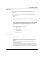
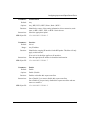
Enabling Source Routing over Token Ring Networks
The IP router can route over Token Ring (TR) networks that contain one or more
source-routing bridges.
In a source-routing network, every endstation that sends out a frame supplies the
frame with the necessary route descriptors so that it can be source routed across
the network. Thus, in order for IP routers to route packets across a source-routing
network, they must act like endstations, supplying route descriptors for each
packet before they send it out onto the network.
2-12
Configuring IP Routers and Interfaces
With endnode support enabled, whenever an IP router receives a packet and
determines that the packet’s next hop is located across a source-routing network,
the router
•
Adds the necessary Routing Information Field (RIF) information to the
packet’s MAC header
•
Sends the packet out onto the network where it is source routed toward the
next hop
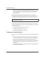
Upon receiving the packet from the Token Ring network, the peer router strips off
the RIF and continues to route the packet toward the destination network address
(Figure 2-5).
End Station 1
Router 1
Token
Ring
Token
Ring
Token
Ring
Bridge A
Router 2
Bridge B
End Station 2
WF2 WF1
SNAP
IP
DATA
WF2 WF1
0830 001A002B 0030
WF2 WF1
SNAP
Packet sent from End Station 1
Source Route RIF
Figure 2-5.
IP
SNAP
DATA
IP
DATA
Packet sent from Router 1
Packet sent from Router 2
IP Routers Source Routing across a Token Ring Network
2-13
Configuring IP Services
The router can send ARP packets over an interface configured for a Token Ring
network. Bay Networks supports both spanning tree explorer (STE) and all route
explorer (ARE) ARP packets.
Site Manager allows you to configure source-route endnode support on a per-circuit
basis. For instructions, see the TR Endstation parameter on page 2-43. Site Manager
also allows you to select STE or ARE ARP packets. For instructions, see the TR
Endstation ARP Type parameter on page 2-51.
Configuring the Trivial File Transfer Protocol
The Trivial File Transfer Protocol (TFTP) is a TCP/IP standard protocol for
transferring files with minimum capability and minimal overhead. TFTP is
implemented on top of the unreliable connectionless datagram delivery service
and is used to move files between network devices.
TFTP was designed to be small and easy to implement. Because it is small, it is
more restrictive, lacking most of the features of the File Transfer Protocol (FTP).
TFTP provides inexpensive, unsophisticated file-transfer service only. It cannot
list directories and provides no authentication.
TFTP runs on top of the User Datagram Protocol (UDP) and uses timeout and
retransmission to ensure that data arrives. Each file transfer begins with a request
to read or write to a file; this request also serves to ask for a connection. If the
server grants the request, the connection is opened and the file is sent in fixedlength blocks (data packets) of 512 bytes. Each data packet contains one block of
data and must be acknowledged by an acknowledgment packet before the next
packet is sent. A data packet of less than 512 bytes terminates the transfer.
If a packet gets lost in the network, the intended recipient will time out and may
retransmit its last packet (which can be data or an acknowledgment), causing the
sender of the lost packet to retransmit the packet. Because the lock-step
acknowledgment guarantees that all older packets have been received, the sender
keeps one packet only on hand for transmission.
Both devices involved in a TFTP transfer are senders and receivers. One device
sends data and receives acknowledgments; the other device sends
acknowledgments and receives data.
2-14
Configuring IP Routers and Interfaces
The IP router includes a client and server implementation of TFTP, enabling the
router to transmit and receive files across an Internet.
For instructions on using Site Manager to specify the operating characteristics of TFTP on
a router, see “Editing TFTP Parameters” on page 2-73.
Defining a Circuitless IP Interface
A circuitless IP interface has an IP address that is not mapped to the address of a
specific circuit. If one or more of the router’s IP interfaces become disabled, this
circuitless feature ensures that the router is always reachable using the circuitless
IP interface address, as long as a viable path to the router exists. The IP router can
support one circuitless IP interface.
IP traffic is delivered to and transmitted from the circuitless interface in the same
way as any other IP interface. In addition, the circuitless IP interface can receive
packets from any application.
When you configure a circuitless IP interface, note the following:
•
You can configure one circuitless IP interface per router. Additional circuitless
IP interfaces will not initialize.
•
You can add IP routing protocols to the circuitless interface. (The current
version of Site Manager allows you to add BGP and OSPF to a circuitless
interface.)
•
You must assign a unique IP address and subnetwork number to the circuitless
IP interface.
•
You cannot configure a circuitless IP interface in nonforwarding mode.
For instructions on using Site Manager to define a circuitless interface and add BGP and
OSPF to the interface, see “Configuring a Circuitless IP Interface” on page 2-62.
Site Manager allows you to specify the slots on which support for the circuitless interface
is enabled. For instructions, see the Slot Mask parameter on page 2-47.
2-15
Configuring IP Services
Configuring the Revised IP Security Option
IP routers support the Department of Defense (DoD) Revised IP Security Option
(RIPSO), as defined in RFC 1108 on a per-interface basis. While RIPSO RFC
1108 specifies both “basic” and “extended” security options, our implementation
supports only the basic option.
RIPSO is a feature that allows end systems and intermediate systems (routers) to
add labels to or process security labels in IP datagrams that they transmit or
receive on an IP network. The labels specify security classifications (for example,
Top Secret, Secret, Confidential, and Unclassified, in descending order), which
can be used to limit the devices that can access these labeled IP datagrams.
As a labeled IP datagram traverses an IP network, only those systems that have the
proper clearance (that is, whose security classification range covers the
classification specified by the datagram) should accept and forward the datagram.
Any system whose security classification range does not cover the classification
specified by the security label should drop the datagram.
Note: RIPSO does not include any method of preventing a system that does
not support RIPSO from simply accepting and forwarding labeled datagrams.
Thus, in order for RIPSO to be effective, all systems in a network must support
RIPSO and process IP datagrams as described.
For instructions on using Site Manager to enable RIPSO support on an IP interface, see
the Enable Security parameter on page 2-49. For complete information on RIPSO
parameters, see “Configuring RIPSO Support” on page 2-76.
2-16
Configuring IP Routers and Interfaces
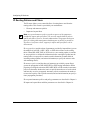
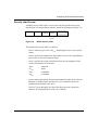
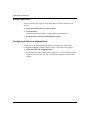
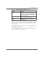
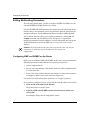
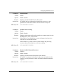
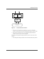
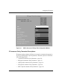
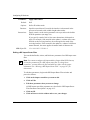
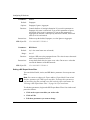
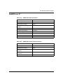
Security Label Format
A RIPSO security label is three or more bytes long and specifies the security
classification level and protection authority values for the datagram (Figure 2-6).
Type
Length
1 Octet
1 Octet
Figure 2-6.
Security
Classification
1 Octet
Protection
Authority
IP Datagram...
1 Octet
or More
RIPSO Security Label
The format of the security label is as follows:
•
Octet 1 contains a type value of 82(16), identifying the basic security option
format.
•
Octet 2 specifies the length of the option (three or more octets, depending on
the presence or absence of authority flags).
•
Octet 3 specifies the security classification levels for the datagrams. Valid
security classification levels include
•
3D(16)
Top Secret
5A(16)
Secret
96(16)
Confidential
AB(16)
Unclassified
Octet 4 and beyond identify the protection authorities under whose rules the
datagram is classified at the specified level. (If no authorities have been
identified, then this field is not used.)
The first 7 bits (0 through 6) are flags. Each flag represents a protection
authority. The flags defined for Octet 4 are as follows:
2-17
Configuring IP Services
Bit 0
GENSER
General
Services (as per
DoD 5200.28)
Bit 1
SIOP-ESI
DoD
(Organization of
the Joint Chiefs
of Staff)
Bit 2
SCI
Central
Intelligence
Agency
Bit 3
NSA
National
Security Agency
Bit 4
DOE
Department of
Energy
Bit 5
Reserved
Bit 6
Reserved
Bit 7
Termination
indicator
Note: Bit 7 acts as a “more” bit, indicating that another octet (containing
additional authority flags) follows.
How RIPSO Works on the Router
When you configure RIPSO on an IP interface, you specify the following
conditions:
2-18
•
A range of acceptable security levels for IP datagrams the interface receives
and transmits
•
A set of required and allowed authority values for IP datagrams the interface
receives and transmits
•
Whether inbound datagrams received on this interface require security labels
•
Whether outbound datagrams transmitted on this interface (either forwarded
or originated by the router) require security labels
Configuring IP Routers and Interfaces
•
Whether datagrams received or transmitted on this interface should have their
labels stripped
You also specify whether the router creates the following types of labels:
•
An implicit label, which the router uses to label unlabeled inbound datagrams,
when required
•
A default label, which the router uses to label unlabeled outbound datagrams,
when required
•
An error label, which the router uses to label ICMP error messages associated
with processing security options
The following sections describe how the router uses this information to handle
labeled IP traffic.
Inbound IP Datagrams
When the router receives an IP datagram on a RIPSO interface, it compares the
security classification and authority values specified in the security label with
those configured on the inbound interface.
If the interface does not require a security label for inbound IP datagrams, then the
router accepts both unlabeled IP datagrams and datagrams that meet the
classification and authority rules described in the next paragraph.
If the interface does require a security label, then for the router to accept the
datagram, the following RISPO conditions must be met:
•
The datagram must be labeled.
•
The security classification value in the datagram’s label must be within the
security-level range configured for the interface.
•
The authority flags in the datagram’s label must include all of the flags
required for the interface and cannot contain any flags not allowed for the
interface.
The router drops any datagrams that do not meet these requirements and generates
an ICMP error message.
On a non-RIPSO interface, the router only accepts unlabeled IP datagrams and IP
datagrams that are labeled as Unclassified with no authority flags set.
2-19
Configuring IP Services
Forwarded IP Datagrams
When the router receives an IP datagram that needs forwarding on a RIPSO
interface, the router compares the security classifications and authority values
specified in the security label with those configured on the outbound interface. So,
before forwarding the datagram, the router
•
Checks that all RIPSO conditions are met (see above)
•
Applies any outbound specific configuration parameters
The router drops any datagrams that do not meet these requirements and generates
an ICMP error message.
Originated IP Datagrams
When the router originates a datagram and the following conditions are true:
•
The datagram needs forwarding through a RIPSO interface
•
The RIPSO interface requires outbound labels for originated datagrams
the router labels the datagram with the default security label before transmitting it.
Unlabeled IP Datagrams
If the router receives an unlabeled IP datagram from an interface on which RIPSO
is not enabled (or on which labels are not required for inbound datagrams), and
the IP datagram needs forwarding to an interface on which RIPSO is enabled and
labels are required for outbound datagrams, then the router labels the datagram
using either an implicit label or default label as follows:
•
If the inbound interface has an implicit label configured, then the router uses it
to label the datagram.
•
If the inbound interface does not have an implicit label configured, then the
router labels the datagram with the default label configured for the outbound
interface.
If the interface does not have an implicit or default label configured, then the
datagram is simply dropped.
2-20
Configuring IP Routers and Interfaces
RIPSO Example
The router in Figure 2-7 has RIPSO configured on all three IP interfaces. The
security ranges specified for each interface vary, as shown. (For simplicity, this
example assumes that none of the interfaces requires any authority flags on
inbound and outbound traffic, but any flags that are present are acceptable.)
When host 1.1.0.1 broadcasts an all-subnets broadcast IP datagram with the
security-level classification set to Secret, the router compares the datagram’s
classification with the range configured on inbound interface 1.1.0.2. Because
Secret is within the range configured on the interface, the router accepts the
datagram. In order to forward the datagram, the router does the following:
•
Compares the datagram’s security level, Secret, to the security-level ranges
configured on interface 1.2.0.2 and 1.3.0.2
•
Forwards the datagram on interface 1.2.0.2, because Secret is within the
security range configured on the interface
•
Does not forward the datagram on interface 1.3.0.2, because Secret is outside
of the security range configured on the interface
Interface
Min. Security
Classification
Max. Security
Classification
1.1.01
Unclassified
Top secret
1.2.02
Secret
Top secret
1.3.0.2
Top secret
Top secret
IP Datagram
1.1.0.1
Secret
IP Data...
Accept inbound datagram? Yes
1.1.0.2
1.2.0.2
1.2.0.1
Figure 2-7.
Forward outbound
datagram?
Yes
1.3.0.2
Forward outbound
datagram?
No
1.3.0.1
RIPSO Network
2-21
Configuring IP Services
Defining a Static Route
A static route is a manually configured route that specifies the transmission path a
datagram must follow, based on the datagram’s destination address. A static route
specifies a transmission path to another network. You configure a static route if
you want to restrict the paths that datagrams follow to paths you specifically
configure.
Static routes remain in IP routing tables until you remove them. Note, however,
that if the interface that was used to reach the next hop in the static route becomes
disabled, the static route disappears from the IP routing table.
For instructions on using Site Manager to configure a static route, see “Configuring Static
Routes” on page 2-63.
Defining a Black Hole for a Supernet
A router that advertises an aggregate route by using a supernet address to
represent multiple explicit routes must be able to discard packets that match the
supernet address but that do not match any of the explicit routes.
For example, consider a router that advertises an aggregate route using the
supernet address 192.32.0.0/255.255.248. The supernet address represents eight
specific networks: 192.32.0.0 through 192.32.7.0. Once the aggregate route has
been propagated, the router receives network traffic for each of these specific
destinations.
At some point, the router loses connectivity to network 192.32.3.0, one of the
networks in the supernet. The router continues to forward traffic that matches
destinations 0.0 through 2.0 and 4.0 through 7.0. However, the router can no
longer find a complete match in the routing table for the disconnected network,
3.0. The router must drop all traffic destined for 192.32.3.0.
To force the router to drop the packet for an unmatched destination, you configure
a special type of static route for a supernet called a black hole. Specifically, you
enter the supernet address/mask pair as the Destination IP Address and Address
Mask parameter values on the IP Static Routes window. To create the black hole,
you enter the black hole encoding (255.255.255.255) as the Next Hop Addr and
Next Hop Mask parameter values.
For instructions on using Site Manager to define a black hole in an aggregate route, see
“Configuring Static Routes” on page 2-63.
2-22
Configuring IP Routers and Interfaces
Configuring Router Discovery
Before a host can send IP datagrams beyond its directly attached subnet, the host
must discover the address of at least one operational router on that subnet. Router
Discovery is an extension of the Internet Control Message Protocol (ICMP) that
enables hosts attached to multicast or broadcast networks to discover the IP
addresses of their neighboring routers.
Routers configured with Router Discovery periodically multicast or broadcast a
router advertisement from each of their interfaces, announcing the IP address or
addresses of that interface. Hosts discover the addresses of their neighboring
routers by listening for these advertisements. Hosts will use the router with the
highest preference level as a gateway.
For instructions on using Site Manager to configure IP Router Discovery, see “Configuring
Router Discovery” on page 2-86.
Specifying the Size of IP Forwarding Tables
To keep to a minimum the amount of time that it spends looking up routes, IP
creates and maintains a cache of frequently used routes — called a forwarding
table — for each IP interface.
A forwarding table is a first-in-first-out (FIFO) buffer. When a datagram arrives on
an IP interface for forwarding, IP performs the following steps:
1. IP searches the forwarding table associated with the interface for the
destination network.
2. If the search is successful, IP dispatches the datagram to the interface noted in
the table entry.
3. If the search is unsuccessful, IP consults the routing table to get the same
information, dispatches the datagram to the appropriate interface, and caches
the information in the appropriate forwarding table — either by appending
information to the table (if the table is not full) or by overwriting the oldest,
first-in table entry (if the table is full).
2-23
Configuring IP Services
If IP flushes a route from the routing table, it also removes the route from the
forwarding tables, thus ensuring that invalid routing information is not retained in
interface-specific caches.
Site Manager allows you to configure the size of the forwarding table associated with an
IP interface by specifying the maximum number of entries in the cache FIFO buffer. For
information, see the Max Forwarding Table Size parameter on page 2-48.
Connecting the Router to a Blacker Front End
The Blacker Front End (BFE) is a classified encryption device used by hosts that
want to communicate across unsecured wide area networks. BFE devices are
typically found in government networks (for example, DSNET), which handle
sensitive data requiring a greater degree of security.
Blacker Front End support allows the router to connect to BFE devices. The BFE
device, in turn, provides the router with encryption services while acting as the
Data Communications Equipment (DCE) end of the connection between the
router and the X.25 network (Figure 2-8).
Hosts using attached BFE devices can communicate with each other over an
unsecured packet-switched network using data paths secured by the encryption
services of the BFEs. These hosts are part of a Red virtual network. The packetswitched network that carries both the data secured by BFEs and any other
unsecured data is known as the Black network.
Router
BFE
X.25 DDN
BFE
Router
BFE
Key
Black Network
Red Network
Figure 2-8.
2-24
Router
Blacker Front End Network Configuration
Configuring IP Routers and Interfaces
BFE devices receive authorization and address translation services from an
Access Control Center residing on the Black network. The ACC makes access
control decisions that determine which hosts are allowed to communicate with
each other. A Key Distribution Center (KDC) residing on the Black network
provides encryption keys and key management services. A BFE device uses these
encryption keys for encrypting traffic between itself and other BFE devices.
The router-to-BFE interface is a modified version of the interface presented in the
1983 DDN X.25 Host Interface Specification. It supports data rates between 1200
b/s and 64 KB/s. In order to support BFE services, the interface must be
configured to support IP with the Revised IP Security Option (RIPSO) enabled.
All IP datagrams transmitted on the interface must contain a RIPSO security label.
The first option in each IP datagram header must be the Basic Security option.
For instructions on using Site Manager to configure support for a BFE encryption device,
see “Configuring Blacker Front End Support” on page 2-89.
BFE Addressing
You can enable BFE support on individual IP interfaces. When you enable BFE
support, the router uses the BFE address-resolution algorithm to map IP addresses
to their corresponding X.121 addresses.
BFE IP-to-X.121 address translation differs from standard DDN address
translation. Each physical router-to-BFE connection is identified by a BFE X.121
network address and a BFE IP address. The format of a BFE X.121 address is
zzzzzpdddbbb
where:
zzzzz
is zero
p
is the BCD encoding of the port ID
ddd
is the BCD encoding of the domain ID
bbb
is the BCD encoding of the BFE ID
2-25
Configuring IP Services
All BFE hosts are members of Class A IP networks. The format of a BFE IP
address is as follows:
nnnnnnnn.Zpppdddd.ddddddbb.bbbbbbbb
where:
nnnnnnnn
identifies the network ID in bits
Z
is zero
ppp
is the port ID in bits
dddd.dddddd
is the domain ID in bits
bb.bbbbbbbb
is the BFE ID in bits
BFE supports only physical addressing. It does not support either logical
addresses or subaddresses.
Each configuration in Table 2-1 and Table 2-2 is expressed as
source device ➔ medium ➔ destination device
For example:
Bay ➔ Eth ➔ Bay
where the source device is a Bay Networks router, the medium is Ethernet, and the
destination device is a Bay Networks router.
A more complex configuration is expressed as
source device ➔ medium ➔ intermediate device ➔ medium ➔ destination device
For example:
Bay ➔ Token ➔ Bay ➔ Token ➔ ES
where the source device is a Bay Networks router, the first medium is a Token
Ring network, the intermediate device is a Bay Networks router, the second
medium is another FDDI, and the destination device is an endstation from another
vendor.
2-26
Configuring IP Routers and Interfaces
Table 2-1.
Source Route Bridge Support for Host-Only Mode
Bridge Configuration
Result
Bay* ➔
OK
Eth† ➔
Bay
Bay
‡
➔ Token ➔
Bay
OK
Bay
**
➔ FDDI ➔
Bay
OK
Bay
†† ➔
➔ PTP
Bay
OK
Bay
‡‡ ➔
➔ FR
Bay
*** ➔ Bay
➔ SMDS
Bay
††† ➔
➔ PPP
Bay
OK
OK
Bay
Bay ➔ Eth➔Bay ➔Token
Fails
‡‡‡
➔ ES
Fails
Bay ➔ Token ➔ Bay ➔ Token ➔ ES
OK
Bay ➔ FDDI ➔ Bay ➔ Token ➔ ES
Fails
Bay ➔ PTP ➔ Bay ➔ Token ➔ ES
Fails
Bay ➔ FR ➔ Bay ➔ Token ➔ ES
Fails
Bay ➔ SDMS ➔ Bay ➔ Token ➔ ES
Fails
Bay ➔ PPP ➔ Bay ➔ Token ➔ ES
Fails
ES ➔ Token ➔ Bay ➔ Eth➔ Bay
Fails
ES ➔ Token ➔ Bay ➔ Token➔ Bay
OK
ES ➔ Token ➔ Bay ➔ FDDI ➔ Bay
Fails
ES ➔ Token ➔ Bay ➔ PTP ➔ Bay
Fails
ES ➔ Token ➔ Bay ➔ FR ➔ Bay
Fails
ES ➔ Token ➔ Bay ➔ SDMS ➔ Bay
Fails
ES ➔ Token ➔ Bay ➔ PPP ➔ Bay
Fails
ES ➔ Token ➔ Bay ➔ Eth ➔ Bay ➔ Token ➔ ES
OK
ES ➔ Token ➔ Bay ➔ Token ➔ Bay ➔ Token ➔ ES
OK
ES ➔ Token ➔ Bay ➔ FDDI ➔ Bay ➔ Token ➔ ES
OK
ES ➔ Token ➔ Bay ➔ PTP ➔ Bay ➔Token ➔ ES
OK
ES ➔ Token ➔ Bay ➔ FR ➔ Bay ➔ Token ➔ ES
OK
ES ➔ Token ➔ Bay ➔ SDMS ➔ Bay ➔ Token ➔ ES
OK
ES ➔ Token ➔ Bay ➔ PPP ➔ Bay ➔ Token ➔ ES
OK
(continued)
2-27
Configuring IP Services
*
Bay Networks router with bridge and IP in host-only mode
†
Ethernet connection
‡
Token Ring connection
**
FDDI connection
††Bay
Networks proprietary point-to-point synchronous connection
‡‡Frame
Relay synchronous connection
***SMDS
synchronous connection
†††PPP
synchronous connection
‡‡‡Station
you are communicating to or from if not Bay Networks
Table 2-2.
Learning Bridge Support for Host-Only Mode
Bridge Configuration
Result
Bay* ➔
OK
Eth† ➔
Bay
Bay
‡
➔ Token ➔
Bay
OK
Bay
**
➔ FDDI ➔
Bay
OK
Bay
†† ➔
➔ PTP
Bay
OK
Bay
‡‡ ➔
➔ FR
Bay
*** ➔ Bay
➔ SMDS
Bay
††† ➔
➔ PPP
Bay
OK
OK
Bay
Bay ➔ Eth➔Bay ➔ Eth
Fails
‡‡‡
➔ ES
OK
Bay ➔ Token ➔ Bay ➔ Eth ➔ ES
Fails
Bay ➔ FDDI ➔ Bay ➔ Eth ➔ ES
OK
Bay ➔ PTP ➔ Bay ➔ Eth ➔ ES
OK
Bay ➔ FR ➔ Bay ➔ Eth ➔ ES
Fails
Bay ➔ SDMS ➔ Bay ➔ Eth ➔ ES
Fails
Bay ➔ PPP ➔ Bay ➔ Eth ➔ ES
Fails
ES ➔ Eth ➔ Bay ➔ Eth ➔ Bay
OK
ES ➔ Eth ➔ Bay ➔ Token ➔ Bay
Fails
ES ➔ Eth ➔ Bay ➔ FDDI ➔ Bay
OK
ES ➔ Eth ➔ Bay ➔ PTP ➔ Bay
OK
ES ➔ Eth ➔ Bay ➔ FR ➔ Bay
Fails
ES ➔ Eth ➔ Bay ➔ SDMS ➔ Bay
Fails
(continued)
2-28
Configuring IP Routers and Interfaces
Table 2-2.
Learning Bridge Support for Host-Only Mode (continued)
Bridge Configuration
Result
ES ➔ Eth ➔ Bay ➔ PPP ➔ Bay
Fails
ES ➔ Eth➔ Bay ➔ Eth ➔ Bay ➔ Eth ➔ ES
OK
ES ➔ Eth ➔ Bay ➔ Token ➔ Bay ➔ Eth ➔ ES
OK
ES ➔ Eth ➔ Bay ➔ FDDI ➔ Bay ➔ Eth ➔ ES
OK
ES ➔ Eth ➔ Bay ➔ PTP ➔ Bay ➔ Eth ➔ ES
OK
ES ➔ Eth ➔ Bay ➔ FR ➔ Bay ➔ Eth ➔ ES
OK
ES ➔ Eth ➔ Bay ➔ SDMS ➔ Bay ➔ Eth ➔ ES
OK
ES ➔ Eth ➔ Bay ➔ PPP ➔ Bay ➔ Eth ➔ ES
OK
*
Bay Networks router with bridge and IP in host-only mode
†
Ethernet connection
‡
Token Ring connection
**
FDDI connection
††Bay
Networks proprietary point-to-point synchronous connection
‡‡Frame
Relay synchronous connection
***SMDS
synchronous connection
†††PPP
synchronous connection
‡‡‡Station
you are communicating to or from if not Bay Networks
IP over ATM
RFC 1577, “Classical IP and ARP over ATM.” is a specification for an
administrative entity within an ATM network called a logical IP subnet (LIS). Bay
Networks supports RFC 1577.
For information on configuring IP interfaces on an ATM LIS, see Configuring
ATM Services.
Site Manager includes IP interface parameters that allow you to specify the
characteristics of an ATMARP interface and to configure an ATM adjacent host. For
information, see “Editing IP Interface Parameters” on page 2-35 and “Configuring a Path
to an Adjacent Host” on page 2-68.
2-29
Configuring IP Services
Configuring Host-Only Mode
By default, the router processes all IP packets addressed to itself and forwards all
other packets. You can, however, configure the router to operate in nonforwarding
— or host-only — mode.
In host-only mode, the router acts as an IP host; it processes packets but does not
forward packets not addressed to itself. In nonforwarding mode, no routing
protocols are activated. Only static routes and adjacent-host routes are available.
Use host-only mode if you want to provide IP management access (by means of
SNMP or TFTP) to all active IP interfaces but want to prohibit the router from
forwarding IP traffic.
For instructions on using Site Manager to configure host-only mode, see the Forwarding
parameter on page 2-54.
If you use host-only mode, you must configure the router to bridge IP traffic not
explicitly addressed to the router. Table 2-1 shows the source-route bridge
configurations that support host-only mode. Table 2-2 shows the learning bridge
configurations that support host-only mode.
2-30
Configuring IP Routers and Interfaces
Editing IP Parameters
This section describes how to edit, or customize, IP parameters. You access all IP
parameters from the Configuration Manager window shown in Figure 2-9. For
each IP parameter, this section describes the default setting, all valid setting
options, the parameter function, instructions for setting the parameter, and the
Management Information Base (MIB) object ID.
Figure 2-9.
Configuration Manager Window
The Technician Interface allows you to modify parameters by issuing set and
commit commands with the MIB object ID. This process is equivalent to
modifying parameters using Site Manager. For more information about using the
Technician Interface to access the MIB, refer to Using Technician Interface
Software.
Caution: The Technician Interface does not verify that the value you enter for
a parameter is valid. Entering an invalid value can corrupt your
configuration.
2-31
Configuring IP Services
Configuring a Circuit and Adding an IP Interface
Before you can add an IP interface to a circuit, you must perform the following
operations to ensure that the slot is properly set up for IP:
1. Open a configuration file.
2. Specify a slot and configure a link module on the slot (if the configuration file
is a local mode file).
3. Select a link or net module connector and configure a circuit on the connector,
or configure a WAN circuit if this connector requires one.
For instructions on performing these operations, see Configuring Routers.
Once you have configured a circuit, you are finished with the Add Circuit window.
1.
Click on OK on the Add Circuit Window.
The Select Protocols window opens.
2.
Select IP from the Select Protocols window and click on OK.
Site Manager displays the IP Configuration window (see Figure 2-10).
3.
Edit the parameters on the screen.
4.
Click on OK if you want to accept the default values for the remaining IP
interface parameters.
Site Manager displays the Configuration Manager window.
5.
Click on Details if you want to edit all IP interface parameters.
Site Manager displays the IP Interfaces window (see Figure 2-11).
2-32
Configuring IP Routers and Interfaces
Figure 2-10.
IP Configuration Window
IP Configuration Parameter Descriptions
This section describes the parameters on the IP Configuration window
(Figure 2-10) that you set to add an IP interface to a circuit.
Parameter:
IP Address
Default:
None
Options:
0.0.0.0 or any valid IP address
Function:
Instructions:
MIB Object ID:
Assigns a 32-bit IP address to the interface.
Enter the IP address of the interface in dotted decimal notation. Enter
0.0.0.0 to configure an unnumbered interface on the circuit.
1.3.6.1.4.1.18.3.5.3.2.1.4.1.4
2-33
Configuring IP Services
Parameter:
Subnet Mask
Default:
None
Options:
The Configuration Manager automatically calculates an appropriate
subnet mask, depending on the class of the network to which the interface
connects. However, you can change the subnet mask with this parameter.
Function:
Specifies the network and subnetwork portion of the 32-bit IP address.
Instructions:
Either accept the assigned subnet mask or enter another subnet mask in
dotted decimal notation. Enter 0.0.0.0 if you are configuring an
unnumbered interface on the circuit.
MIB Object ID:
Parameter:
1.3.6.1.4.1.18.3.5.3.2.1.4.1.6
Transmit Bcast Addr
Default:
0.0.0.0
Options:
0.0.0.0 or any valid IP broadcast address
Function:
Specifies the broadcast address that this IP subnet uses to broadcast
packets.
Accepting 0.0.0.0 for this parameter specifies that the IP router will use a
broadcast address with a host portion of all 1s. Accepting 0.0.0.0 does not
configure the router to use the address 0.0.0.0 to broadcast packets. For
example, if you have IP address 123.1.1.1 and a subnet mask of
255.255.255.0, accepting the default value 0.0.0.0 configures the IP router
to use the address 123.1.1.255 to broadcast packets. To set the explicit
broadcast address of all 1s, enter 255.255.255.255 for this parameter.
Instructions:
Accept the default, 0.0.0.0, unless the calculated broadcast address (host
portion) of all 1s is not adequate. If this is the case, then enter the
appropriate IP broadcast address in dotted decimal notation.
If you set the IP Address parameter to 0.0.0.0 (to configure an
unnumbered interface), Site Manager automatically sets this parameter to
255.255.255.255.
MIB Object ID:
2-34
1.3.6.1.4.1.18.3.5.3.2.1.4.1.8
Configuring IP Routers and Interfaces
Parameter:
UnNumbered Assoc Address
Default:
None
Options:
Any valid IP address
Function:
Specifies an address that IP uses when sourcing a packet.
RIP uses this address to make decisions about advertising subnets over
the unnumbered interface. RIP advertises subnets over the unnumbered
interface if the subnets have the same mask as the associated address.
Instructions:
Specify the address of any numbered interface on the router.
If you are running RIP over the unnumbered interface and if you are using
a subnet address as the associated address, the local and remote associated
address should have the same network number. If you configure a local
and remote associated address using different network numbers, you must
use RIP2 mode.
MIB Object ID:
1.3.6.1.4.1.18.3.5.3.2.1.4.1.110
Editing IP Interface Parameters
To edit an IP interface, begin at the Configuration Manager window shown in
Figure 2-9 and proceed as follows:
1.
Select Protocols➔IP➔Interfaces.
The IP Interfaces window opens (Figure 2-11). It lists all IP interfaces
configured on the router.
2.
Click on the interface you want to edit.
3.
Edit those parameters you want to change.
All IP interface parameters are described in the following section.
4.
Click on Apply to implement your changes.
5.
Click on Done to exit the window.
2-35
Configuring IP Services
Figure 2-11.
IP Interfaces Window
Note: When you reconfigure an interface in dynamic mode, IP restarts on that
interface. Thus, if the interface you reconfigure is the interface that supports
Site Manager’s SNMP connection to the router, restarting IP on that interface
will cause Site Manager to temporarily lose its router connection and to
display a warning message. To verify that the change took effect, display the
IP Global Parameters window and inspect the setting.
If you are configuring IP over an SMDS circuit, be sure to enter the correct
addresses in the MAC Address, SMDS Group Address, and SMDS Arp Req
Address parameter boxes displayed on this screen. These addresses are the
same as those you entered in the Individual Address, Group Address, and ARP
Address parameters of the SMDS Configuration window when you configured
SMDS.
2-36
Configuring IP Routers and Interfaces
IP Interface Parameter Descriptions
Use the following descriptions to set parameters on the IP Interfaces window.
Parameter:
Enable
Default:
Enable
Options:
Enable | Disable
Function:
Instructions:
MIB Object ID:
Parameter:
Enables or disables IP routing on this interface.
Set to Disable to disable IP routing over this circuit.
1.3.6.1.4.1.18.3.5.3.2.1.4.1.2
Subnet Mask
Default:
You specified the subnet mask when you added IP to the circuit.
Options:
Depend on the class of the network to which the interface connects
Function:
Instructions:
MIB Object ID:
Specifies the network and subnetwork portion of the 32-bit IP address.
Enter the subnet mask in dotted decimal notation.
1.3.6.1.4.1.18.3.5.3.2.1.4.1.6
2-37
Configuring IP Services
Parameter:
Default:
You specified the broadcast address when you added IP to the circuit.
Options:
0.0.0.0 or any IP address
Function:
Instructions:
MIB Object ID:
Parameter:
Default:
Range:
Specifies the broadcast address that the IP router uses to broadcast
packets. Accepting 0.0.0.0 for the broadcast address specifies that the IP
router will use a broadcast address with a host portion of all 1s. Accepting
0.0.0.0 does not configure the router to use the address 0.0.0.0 to
broadcast packets. For example, if you have set the IP address to
123.1.1.1 and the subnet mask to 255.255.255.0, accepting the default
value 0.0.0.0 configures the IP router to use the address 123.1.1.255 to
broadcast packets. For the explicit broadcast address of all 1s, enter
255.255.255.255 for this parameter.
Accept the default, 0.0.0.0, unless the calculated broadcast address (host
portion) of all 1s is not adequate. If this is the case, then enter the
appropriate IP broadcast address in dotted decimal notation.
1.3.6.1.4.1.18.3.5.3.2.1.4.1.9
Interface Cost
1
1 to the value of the RIP diameter (maximum 127)
Function:
Sets the cost of this interface. The interface cost is added to routes learned
on this interface through RIP and is specified in subsequent RIP packets
transmitted out other interfaces.
Instructions:
Enter the interface cost value (standard RIP implementation assigns a cost
of 1); however, keep in mind that increasing this value causes the upper
bound set by the RIP Network Diameter parameter to be attained more
rapidly.
MIB Object ID:
2-38
Broadcast Address
1.3.6.1.4.1.18.3.5.3.2.1.4.1.8
Configuring IP Routers and Interfaces
Parameter:
MTU Discovery
Default:
Off
Options:
On | Off
Function:
Specifies whether the Reply MTU option (option 11 in RFC 1063) is
enabled on this interface. When the option is enabled, this interface
responds to Probe MTUs (option 12 in RFC 1063). A Probe MTU
requests the minimum MTU (maximum transmission unit) of all
networks an IP datagram must traverse from source to destination. By
enabling this interface to respond to Probe MTUs, you eliminate transit
fragmentation and destination reassembly for datagrams destined for this
interface and, therefore, decrease network load.
Instructions:
Select On to enable the Reply MTU option on this interface; select Off to
disable the option on this interface.
MIB Object ID:
Parameter:
1.3.6.1.4.1.18.3.5.3.2.1.4.1.10
Addr Mask Reply
Default:
Off
Options:
On | Off
Function:
Instructions:
MIB Object ID:
Specifies whether this interface generates ICMP (Internet Control
Message Protocol) address-mask-reply messages in response to valid
address-mask-request messages. The interface generates ICMP addressmask-reply messages in compliance with the relevant sections of RFCs
950 and 1009.
Select On to enable ICMP address-mask-reply message generation on this
interface. Select Off to disable ICMP address-mask-reply message
generation on this interface.
1.3.6.1.4.1.18.3.5.3.2.1.4.1.11
2-39
Configuring IP Services
Parameter:
All Subnet Bcast
Default:
Off
Options:
On | Off
Function:
Instructions:
MIB Object ID:
Parameter:
Specifies whether or not the IP router floods ASB datagrams it receives
out this interface. An ASB datagram has a destination address equal to the
broadcast address for an entire network (all subnets). For example, if a
network interface serves the subnet 128.10.2.1 with a subnet mask of
255.255.255.0, the IP router considers any datagram with a destination
address of 128.10.255.255 or 128.10.0.0 to be an ASB datagram.
Specify On if you want the IP router to flood ASBs out this interface;
specify Off to restrict the router from flooding ASBs out this interface.
1.3.6.1.4.1.18.3.5.3.2.1.4.1.12
Address Resolution
Default:
ARP
Options:
ARP | X.25_DDN | X.25_PDN | INARP |
ARPINARP | NONE | X.25 BFEDDN | PROBE | ARPPROBE
Function:
Instructions:
Indicates the address resolution scheme for this interface. The default
option, ARP, enables ARP on this interface. The option INARP (Inverse
ARP) enables the address resolution for Frame Relay interfaces. It is used
to discover the IP address of the station at the remote end of the virtual
circuit. The PROBE option enables HP Probe for Ethernet interfaces.
Depending on your network requirements, select
•
•
•
•
•
•
MIB Object ID:
2-40
INARP only when all Frame Relay stations support Inverse ARP.
ARPINARP for your Frame Relay interfaces. ARPINARP enables
both ARP and Inverse ARP.
X.25_DDN for your X.25 DDN interfaces.
X.25_PDN for your X.25 PDN interfaces.
PROBE to enable HP Probe on the interface.
ARPPROBE to enable both ARP and HP Probe.
1.3.6.1.4.1.18.3.5.3.2.1.4.1.13
Configuring IP Routers and Interfaces
Parameter:
Proxy
Default:
Off
Options:
On | Off
Function:
Specifies whether this interface uses Proxy ARP to respond to ARPs for a
remote network.
Instructions:
Select On to enable Proxy ARP on this interface. In order to enable Proxy
ARP, you must have set the ARP parameter to Enable for this interface.
When you enable Proxy ARP, the IP router assumes responsibility for IP
datagrams destined for the remote network. To enable Proxy ARP for
subnets reachable via a default route, also set the Enable Default Route
for Subnets parameter to Enable. To enable Proxy ARP for remote
destinations on other networks, set the Nonlocal ARP Destination
parameter to Accept. Select Off to disable Proxy ARP on this interface.
MIB Object ID:
Parameter:
1.3.6.1.4.1.18.3.5.3.2.1.4.1.14
Host Cache
Default:
Off
Options:
Off | 120 | 180 | 240 | 300 | 600 | 900 | 1200 (seconds)
Function:
Specifies whether the IP router times out entries in the address-resolution
cache for this interface, and specifies the timeout interval in seconds if the
interface does time out entries. The address-resolution cache contains
host physical addresses learned by means of ARP or Proxy ARP. A host
entry is timed out (deleted) if the IP router sends no traffic destined for
that host within the specified timeout period.
Instructions:
Select Off to disable timeout on this interface; the IP router does not time
out address-resolution cache entries. Select one of the other options to
enable timeout with a timeout interval equal to the value you select (for
example, 120 seconds); the IP router removes address-resolution cache
entries that have not been accessed within the specified number of
seconds. Once an entry is removed, the IP router must use ARP to reacquire the physical-level address.
MIB Object ID:
1.3.6.1.4.1.18.3.5.3.2.1.4.1.15
2-41
Configuring IP Services
Parameter:
Checksum
Default:
On
Options:
On | Off
Function:
Specifies whether UDP checksum processing is enabled on this interface.
Instructions:
Select On to enable UDP checksum processing for the interface; all
outgoing and incoming UDP datagrams are subject to checksumming.
You should select On in virtually all instances. Select Off to disable UDP
checksum processing and provide backward compatibility with UNIX
BSD 4.1.
MIB Object ID:
Parameter:
1.3.6.1.4.1.18.3.5.3.2.1.4.1.16
MAC Address
Default:
None
Options:
0 | a user-specified MAC address | if the interface is on an SMDS circuit,
the entire E.164 address — for example, E1 617 275 5000 FFFF
Function:
Specifies a MAC (media access control) address for this IP interface. The
IP router will use its IP address and this MAC address when transmitting
and receiving packets on this interface.
Instructions:
Enter 0 to configure the IP router to use its IP address and the circuit’s
MAC address when transmitting packets on this interface. Enter your own
MAC address to configure the IP router to use its IP address and the
specified MAC address when transmitting packets on this interface.
To configure this parameter for a multinet or multigroup configuration,
refer to Configuring SMDS Services.
MIB Object ID:
2-42
1.3.6.1.4.1.18.3.5.3.2.1.4.1.17
Configuring IP Routers and Interfaces
Parameter:
TR Endstation
Default:
Off
Options:
On | Off
Function:
Instructions:
MIB Object ID:
Parameter:
Specifies source routing over Token Ring selection.
Use the On option to enable the parameter.
1.3.6.1.4.1.18.3.5.3.2.1.4.1.64
Redirects
Default:
Enable
Options:
Enable | Disable
Function:
Indicates whether or not this interface sends out ICMP redirects.
ICMP redirects are messages sent by the router to alert a host that it
should be using a different path to route data.
Instructions:
MIB Object ID:
Reset to Disable if you do not want this interface to send out redirects. For
example, in a Frame Relay network, two stations on the same network
may not be directly connected if the network is not fully meshed. Thus, in
this case, you would set Redirects to Disable.
1.3.6.1.4.1.18.3.5.3.2.1.4.1.70
2-43
Configuring IP Services
Parameter:
Enet Arp Encaps
Default:
ARP Ethernet
Options:
ARP Ethernet | ARP SNAP | ARP Both |
Probe LSAP | ARP Ethernet/Probe LSAP |
ARP SNAP/Probe LSAP | ARP Both/Probe LSAP
Function:
Defines the datalink encapsulation to use for ARP and HP Probe packets
generated at this interface if the underlying medium is Ethernet. This
parameter is ignored if the underlying medium is anything other than
Ethernet.
Instructions:
Depending on the selection you have made for the ARP Resolution
parameter (ARP, Probe, or ARP/Probe), select the appropriate
encapsulation option. If your address-resolution scheme is ARP only,
select Ethernet encapsulation, SNAP encapsulation, or Ethernet/SNAP
encapsulation. If your resolution scheme is HP Probe only, select LSAP
encapsulation. If your resolution scheme is ARP/Probe, select Ethernet/
LSAP encapsulation, SNAP/LSAP encapsulation, or Ethernet/SNAP/
LSAP encapsulation.
MIB Object ID:
Parameter:
1.3.6.1.4.1.18.3.5.3.2.1.4.1.71
SMDS Group Address
Default:
None
Options:
A complete SMDS E.164 address specified by the SMDS subscription
agreement that you have with your SMDS provider
Function:
Instructions:
Provides a MAC-layer multicast address for this IP interface in an SMDS
network. This parameter is displayed only if this is an SMDS circuit.
Enter an entire E.164 address — for example, E1 617 555 1212 FFFF.
To configure this parameter for a multinet or multigroup configuration,
refer to Configuring SMDS Services.
MIB Object ID:
2-44
1.3.6.1.4.1.18.3.5.3.2.1.4.1.65
Configuring IP Routers and Interfaces
Parameter:
SMDS Arp Req Address
Default:
None
Options:
A complete SMDS E.164 address specified by the SMDS subscription
agreement that you have with your SMDS provider
Function:
Instructions:
Provides an address-resolution multicast address for this IP interface in an
SMDS network. This parameter is only displayed if this is an SMDS
circuit.
Enter an entire E.164 address — for example, E1 617 555 1212 FFFF.
To configure this parameter for a multinet or multigroup configuration,
refer to Configuring SMDS Services.
MIB Object ID:
Parameter:
1.3.6.1.4.1.18.3.5.3.2.1.4.1.66
WAN Broadcast
Default:
0
Options:
Any decimal number
Function:
Instructions:
MIB Object ID:
Provides a broadcast address for this IP interface in a Frame Relay
network. If you enter a value for this parameter, the Frame Relay switch,
rather than the router, will broadcast the message. This parameter is
displayed only if this is a Frame Relay circuit.
Enter the broadcast address provided by the Frame Relay subscription
agreement.
1.3.6.1.4.1.18.3.5.3.2.1.4.1.67
2-45
Configuring IP Services
Parameter:
Default:
0
Options:
Any decimal number
Function:
Provides a multicast address for this IP interface that will send messages
to all OSPF routers in a Frame Relay network. If you enter a value for this
parameter, the Frame Relay switch, rather than the router, will send the
message to all OSPF routers. This parameter has meaning only if OSPF
has been added to this interface.
Instructions:
Enter the multicast address for all OSPF routers as provided by the Frame
Relay subscription agreement.
MIB Object ID:
Parameter:
1.3.6.1.4.1.18.3.5.3.2.1.4.1.68
WAN Multicast #2
Default:
0
Options:
Any decimal number
Function:
Instructions:
MIB Object ID:
2-46
WAN Multicast #1
Provides a multicast address for this IP interface that will send messages
to all OSPF designated routers in a Frame Relay network. If you enter a
value for this parameter, the Frame Relay switch, rather than the router,
will send the message to all OSPF designated routers. This parameter has
meaning only if OSPF has been added to this interface.
Enter the multicast address for all OSPF designated routers as provided
by the Frame Relay subscription agreement.
1.3.6.1.4.1.18.3.5.3.2.1.4.1.69
Configuring IP Routers and Interfaces
Parameter:
Slot Mask
Default:
Slot-mask bit set to 1 (enabling circuitless IP interface support) for every
router slot running IP
Options:
For each slot in the router, Site Manager allows you to set the slot-mask
bit to 1 (circuitless IP interface support enabled) or 0 (circuitless IP
interface support disabled)
Function:
Specifies whether circuitless IP interface support is enabled or disabled on
each slot in the router.
Instructions:
If you have configured a circuitless IP interface and do not wish it to run
on certain slots, set the slot-mask bit to 0 on those slots. Be certain to keep
the slot-mask bit set to 1 on at least one slot running IP; otherwise, the
circuitless IP interface will not initialize. Setting the slot-mask bit
parameter to 1 on an empty slot, a slot containing a system resource
module, or a slot with no IP support does not affect the circuitless IP
interface.
MIB Object ID:
1.3.6.1.4.1.18.3.5.3.2.1.4.1.75
2-47
Configuring IP Services
Parameter:
Default:
Range:
Function:
Instructions:
Max Forwarding Table Size
128 entries
64-entry minimum; no maximum
Specifies the maximum number of entries allowed in the forwarding table
at one time.
Specify a forwarding table size for each interface.
This parameter controls the number of destinations that are cached in the
forwarding table on this receiving interface. When this interface receives
an IP packet, the router looks up the destination in the forwarding table.
Therefore, an interface that receives packets that are destined for a large
number of different destinations may benefit from a larger forwarding
table. The larger the number of entries, the more likely it is that the
destination will already be in the forwarding table and the faster the route
lookups will be for those destinations.
Configuring a forwarding table size that is larger than necessary reduces
the total amount of memory usable by other applications. Configuring a
routing table too small can affect overall router performance. A check of
the number of cache hits and misses will help determine the optimal size
of the forwarding table. For debugging purposes, if you see the
wfIpInterfaceCacheMisses statistic going up at an alarming rate, you
should consider increasing the table size. However, an occasional cache
miss does not warrant an increase in table size.
MIB Object ID:
2-48
1.3.6.1.4.1.18.3.5.3.2.1.4.1.104
Configuring IP Routers and Interfaces
Parameter:
Enable Security
Default:
Disable
Options:
Enable | Disable
Function:
Specifies whether Revised IP Security Option (RIPSO) is enabled for the
interface.
Instructions:
If you do not support RIPSO on your network, simply accept the default
setting, Disable. If you are configuring RISPO support, set this parameter
to Enable. Then see “Configuring RIPSO Support” for instructions on
setting the rest of the RIPSO parameters that you must configure.
MIB Object ID:
1.3.6.1.4.1.18.3.5.3.2.1.4.1.76
Note: Once you set this parameter to Enable, you can access the rest of the
RIPSO parameters. If you do not enable this parameter, Site Manager does not
activate the RIPSO parameters.
Parameter:
UnNumbered Assoc Alternate
Default:
Disable
Options:
Enable | Disable
Function:
Instructions:
MIB Object ID:
Automatically assigns an alternate associated address to an unnumbered
interface in the event that the primary associated address has gone down.
IP uses the first available interface.
Use the alternate unnumbered address option to ensure that the
unnumbered interface has a usable associated address on the router.
1.3.6.1.4.1.18.3.5.3.2.1.4.1.111
2-49
Configuring IP Services
Parameter:
ATM ARP Mode
Default:
Client
Options:
Client | Server
Function:
Instructions:
MIB Object ID:
Parameter:
Default:
Range:
Specifies whether the router is running as an ATM client or server on this
interface.
You must configure one ATMARP server for each logical IP subnet you
define.
1.3.6.1.4.1.18.3.5.3.2.1.4.1.112
ARP Server ATM Address Network Prefix
None
XX000000000000000000000000 to
XXFFFFFFFFFFFFFFFFFFFFFFF
where XX = 39, 45, or 47
Function:
Defines the ATM address network prefix of the ATMARP server on your
network.
Instructions:
Enter the ATM address network prefix of the ATMARP server on your
network. A complete ATM address consists of a network prefix and a user
part. Use the ARP Server ATM Address User Part parameter to supply the
user part of the ATM address.
MIB Object ID:
2-50
1.3.6.1.4.1.18.3.5.3.2.1.4.1.113
Configuring IP Routers and Interfaces
Parameter:
Default:
Range:
Function:
Instructions:
ARP Server ATM Address User Part
None
XX00000000000000 to FEFFFFFFFFFFFF
Defines the user part (suffix) of the ATM address for the ATM ARP server
on your network. The user part suffix consists of a 6-byte endstation
identifier and a 1-byte selector field.
Enter the user part suffix of the ATM ARP server on your network. A
complete ATM address consists of a network prefix and a user part. Use
the ARP Server ATM Address Network Prefix parameter to supply the
network part of the ATM address.
MIB Object ID:
1.3.6.1.4.1.18.3.5.3.2.1.4.1.113
Parameter:
Registration Refresh Interval
Default:
900 seconds for a client
1200 seconds for a server
Options:
Any interval (in seconds)
Function:
For a client, this parameter specifies the interval between registration
refreshes. For a server, this parameter specifies the duration for which the
registration is valid.
Instructions:
Determine whether ATMARP is running as a client or as a server on this
interface and enter an appropriate value.
MIB Object ID:
Parameter:
1.3.6.1.4.1.18.3.5.3.2.1.4.1.115
TR Endstation ARP Type
Default:
STE
Options:
STE | ARE
Function:
Instructions:
MIB Object ID:
Specifies the ARP type for an interface configured for Token Ring
support.
For spanning tree explorer (STE) ARP packets, use the default. For all
route explorer (ARE) packets, select ARE. Set the TR Endstation
parameter to ON.
1.3.6.1.4.1.18.3.5.3.2.1.4.1.127
2-51
Configuring IP Services
Editing IP Global Parameters
To edit IP global parameters, begin at the Configuration Manager window shown
in Figure 2-9 and proceed as follows:
1.
Select Protocols➔IP➔Global.
The Edit IP Global Parameters window opens (Figure 2-12).
2.
Edit those parameters you want to change.
Note: When you edit parameters in dynamic mode, the IP router restarts,
causing Site Manager to lose its router connection temporarily, and to display
a warning message. To verify that the change took effect, redisplay the IP
Global Parameters window and inspect the setting.
2-52
Configuring IP Routers and Interfaces
3.
Figure 2-12.
Click on OK to exit the window and save your changes when you are
finished.
Edit IP Global Parameters Window
IP Global Parameter Descriptions
Use the following descriptions to set parameters on the IP Global Parameters
window.
2-53
Configuring IP Services
Parameter:
Enable
Default:
This parameter defaults to Enable when you add IP support to a circuit.
Options:
Enable | Disable
Function:
Instructions:
MIB Object ID:
Specifies the state of the IP router software.
Select Enable if you have previously disabled the IP router software and
now wish to re-enable it. Select Disable to disable the IP router software.
1.3.6.1.4.1.18.3.5.3.2.1.1.2
Note: In dynamic mode, when you set this parameter to Disable, you
immediately prohibit all Site Manager communication with the router.
Parameter:
Forwarding
Default:
Forwarding
Options:
Forwarding | Not Forwarding
Function:
Instructions:
Specifies whether the IP router forwards IP traffic that is not explicitly
addressed to it.
Select Forwarding if you want the IP router to route (forward) IP traffic.
Forwarding configures the IP router to process all broadcast packets and
all IP packets explicitly addressed to it, and to route all other IP packets.
Select Not Forwarding if you want to provide IP management access (by
means of TFTP and SNMP) to all active IP interfaces but also want to
prohibit the IP router from forwarding IP traffic. You must specify an
identical IP address and mask combination for each active IP interface
that will provide management access. Not Forwarding configures the IP
router to act as an IP host; it does not forward IP traffic, but it still
processes packets explicitly addressed to it. In Not Forwarding mode,
only static routes and adjacent-host routes are allowed. No routing
protocols are initiated.
Because the IP router does not forward IP traffic in Not Forwarding mode,
you must configure the router to bridge IP traffic not explicitly addressed
to it. You must configure the bridge for each circuit that conveys IP
datagrams. The bridge will then forward all IP datagrams that are not
explicitly addressed to the router.
MIB Object ID:
2-54
1.3.6.1.4.1.18.3.5.3.2.1.1.4
Configuring IP Routers and Interfaces
Parameter:
ARP Forwarding
Default:
Forwarding
Options:
Forwarding | Not Forwarding
Function:
Instructions:
MIB Object ID:
Parameter:
Specifies how ARP should act in relation to IP’s forwarding state. Note
that Forwarding means IP is in forwarding mode. If this parameter is set
to Forwarding, then ARP packets are either consumed (if destined for the
router) or dropped. If this parameter is set to Not Forwarding, ARP
packets are consumed, if destined for the router, or bridged onto
remaining ARP interfaces.
Always set this parameter the way you set the Forwarding parameter.
1.3.6.1.4.1.18.3.5.3.1.1.3
Nonlocal ARP Source
Default:
Drop
Options:
Drop | Drop and Log
Function:
Instructions:
MIB Object ID:
Determines what happens when IP encounters an invalid ARP source
address. If the parameter is set to Drop and Log, IP logs an invalid ARP
source address when processing an ARP request. If this parameter is set to
Drop, IP does not log the invalid ARP source address. In either case, IP
drops the invalid ARP request.
If you want to log the invalid ARP source address, set the parameter to
Drop and Log. Otherwise, set the parameter to Drop.
1.3.6.1.4.1.18.3.5.3.1.1.4
2-55
Configuring IP Services
Parameter:
Default:
Drop
Options:
Drop | Accept
Function:
Instructions:
MIB Object ID:
Parameter:
Default:
Range:
Function:
Instructions:
MIB Object ID:
2-56
Nonlocal ARP Destination
Determines whether IP drops ARP requests in which the source and
destination addresses are located in different networks or subnetworks.
This parameter allows Proxy ARP to generate replies when the source and
destination networks in the ARP request are different.
To process ARP requests with source and destination addresses from
different networks, set the parameter to Accept. The Proxy parameter
must be set to Enable for the router to generate ARP replies.
1.3.6.1.4.1.18.3.5.3.1.1.5
Default TTL
30
1 to 255 hops
Specifies the starting value of the Time to Live (TTL) counter for each
packet the router originates and transmits (called a source packet). When
the router transmits a source packet, the TTL counter starts to decrement.
Each router, or hop, that the packet traverses decrements the TTL counter
by one. When the counter reaches zero, the router discards the packet
unless it is destined for a locally attached network. The TTL counter
prevents packets from looping endlessly through the network.
Enter the maximum number of hops a source packet can traverse.
1.3.6.1.4.1.18.3.5.3.2.1.1.5
Configuring IP Routers and Interfaces
Parameter:
Default:
Range:
RIP Diameter
15
1 to 127
Function:
Specifies the value, or hop count, the Routing Information Protocol (RIP)
uses to denote infinity. In order for RIP to operate properly, every router
within the network must be configured with an identical RIP diameter
value. If RIP is not enabled, this parameter specifies the maximum
number of hops within the autonomous system; if RIP is not enabled, the
IP router still must understand network width.
Instructions:
You must set this parameter so that none of the interface cost, static cost,
or route filter cost parameters exceed the RIP diameter. We recommend
that you accept the default RIP diameter value of 15.
MIB Object ID:
1.3.6.1.4.1.18.3.5.3.2.1.1.6
2-57
Configuring IP Services
Parameter:
Routing MIB Table(s)
Note: This parameter is not valid in software versions later than Version 7.70.
Default:
Route
Options:
None | Route | Forward | Both
Function:
Instructions:
MIB Object ID:
2-58
Specifies which MIB routing tables IP maintains. IP uses these MIB
routing tables only to store statistics; do not confuse them with the routing
tables maintained to route packets. Maintaining both the Routing and
Forwarding tables uses more memory than maintaining either. In the
absence of variable-length subnet masks, these tables are identical. The
routing table does not support variable-length subnet masks. This table is
MIB-II compliant. The forwarding table does support variable-length
subnet masks. It is not MIB-II compliant.
Depending on your network requirements, select
•
None, to disable maintenance of both tables
•
Route, if you are not using variable-length subnet masks
•
Forward, if you are using variable-length subnet masks and want to
maintain statistics on them
•
Both, if you are using other network management applications to
manage the router
1.3.6.1.4.1.18.3.5.3.2.1.1.8.
Configuring IP Routers and Interfaces
Parameter:
Zero Subnet Enable
Default:
Disable
Options:
Enable | Disable
Function:
Specifies whether an interface address whose subnet portion is all zeros
should be declared legal or not. If you set this parameter to Enable, then
you can configure IP interfaces with a subnet ID of zero. Setting this
parameter to Disable prevents you from doing so.
Instructions:
Accept the default, Disable, if you do not have any interfaces that have a
zero subnet ID. Otherwise, reset this parameter to Enable.
The use of all-zero subnet addresses is discouraged for the following
reason: if an all-zero subnet address and an all-zero broadcast address are
both valid, the router cannot distinguish an all-subnets broadcast from a
directed broadcast for the zero subnet.
MIB Object ID:
Parameter:
Default:
Range:
1.3.6.1.4.1.18.3.5.3.2.1.1.10
Estimated Networks
0
0 to 2147483647
Function:
Allows the IP software to preallocate system resources based on the
anticipated size of the routing table. Preallocation of memory increases
the speed with which IP software can learn routes because it removes the
overhead caused by dynamic memory allocation. Preallocation also
makes better use of memory and reduces the amount of memory required.
Instructions:
Set to the number of networks (including unique subnets) that you expect.
Avoid using a number that is excessively large. This will cause a wasteful
overallocation of memory.
If you use the default value, 0, IP software preallocates memory for 500
routing table entries.
MIB Object ID:
1.3.6.1.4.1.18.3.5.3.2.1.1.11
2-59
Configuring IP Services
Parameter:
Default:
Range:
Function:
Instructions:
Estimated Hosts
0
0 to 2147483647
Allows the IP software to preallocate system resources based on the
anticipated size of the routing table. Preallocation of memory increases
the speed with which IP software can learn routes because it removes the
overhead caused by dynamic memory allocation.
Set to the number of hosts that you expect. Avoid using a number that is
excessively large. This will cause a wasteful overallocation of memory.
If you use the default value, 0, IP software preallocates memory for 500
routing table entries.
MIB Object ID:
Parameter:
Enable Default Route for Subnets
Default:
Disable
Options:
Enable | Disable
Function:
Instructions:
MIB Object ID:
2-60
1.3.6.1.4.1.18.3.5.3.2.1.1.13
Specifies whether the IP router uses a default route for unknown subnets.
The default route must be present in the routing table. When you set this
parameter to Enable, the IP router uses a default route. When you set this
parameter to Disable, the IP router does not use a default route.
Accept the default, Disable, if you do not want the IP router to use a
default route for unknown subnets. Otherwise, reset this parameter to
Enable.
1.3.6.1.4.1.18.3.5.3.2.1.1.14
Configuring IP Routers and Interfaces
Parameter:
Maximum Policy Rules
Default:
Range:
Function:
Instructions:
MIB Object ID:
Parameter:
32
Any integer
Specifies the maximum number of policy rules that can be configured per
policy type (Accept or Announce) per protocol.
To configure more than 32 Accept or Announce policy rules for a
protocol, you must set this parameter to a larger value. IP will round the
value up to the next multiple of 32.
1.3.6.1.4.1.18.3.5.3.2.1.1.15
Route Filter Support
Default:
Enable
Options:
Enable | Disable
Function:
Instructions:
MIB Object ID:
Specifies whether or not IP supports route filters.
If you do not require support for route filters, select Disable. Otherwise,
use the default.
1.3.6.1.4.1.18.3.5.3.2.1.1.16
Deleting IP from an Interface
To delete IP from an interface on which it is currently configured, begin at the
Configuration Manager window (Figure 2-9) and proceed as follows:
1.
Click on the connector from which you want to delete IP services.
2.
Click on Edit Circuit.
3.
Select Protocols➔Add or Delete.
The Select Protocols window opens. The IP button is highlighted to show that
IP is enabled on the circuit.
4.
Click on IP to deselect it.
5.
Click on OK to exit the window.
6.
Select File➔Exit to exit the Circuit Definition window and return to the
Configuration Manager window.
2-61
Configuring IP Services
Configuring a Circuitless IP Interface
Note: The IP router supports one circuitless IP interface.
To configure a circuitless IP interface, begin at the Configuration Manager
window shown in Figure 2-9 and proceed as follows:
1.
Select Protocols➔IP➔Circuitless IP➔Create to display the IP
Configuration window.
2.
Edit the parameters on the IP Configuration window.
The section “IP Configuration Parameter Descriptions” on page 2-33
describes these parameters.
3.
Click on OK to save the circuitless IP interface.
A special Select Protocols window opens, listing the protocols you can
configure on a circuitless interface (Figure 2-13).
4.
Select a protocol and click on OK.
Adding a Protocol to a Circuitless Interface
Once you have created a circuitless interface on the router, you can add a protocol
to the interface. Begin at the Configuration Manager window shown in Figure 2-9
and proceed as follows:
1.
Select Protocols➔IP➔Circuitless IP➔Change Protocols.
A Select Protocols window opens, listing the protocols you can add to the
circuitless interface (Figure 2-13).
2.
Select a protocol and click on OK.
The router adds the protocol to the circuitless IP interface.
2-62
Configuring IP Routers and Interfaces
Figure 2-13.
Select Protocols (Circuitless Interface) Window
Configuring Static Routes
To add, edit, or delete static routes, begin at the Configuration Manager window
shown in Figure 2-9 and proceed as follows:
1.
Select Protocols➔IP➔Static Routes.
The IP Static Routes window opens, listing all static routes configured on the
router. You add, edit, and delete static routes from this window.
2.
Add, edit, or delete static routes as described in the following sections.
Adding a Static Route
To add a static route, begin at the IP Static Routes window and proceed as follows:
1.
Click on Add.
The IP Configuration window (Figure 2-14) opens.
2-63
Configuring IP Services
Figure 2-14.
2.
Edit the parameters.
3.
Click on OK to exit the IP Configuration window.
IP Configuration Window for a Static Route
Editing a Static Route
You can edit the Enable, Cost, Next Hop Addr, Next Hop Mask, Preference, and
Unnumbered CCT Name parameters for a static route. To edit these parameters,
begin at the IP Static Routes window and proceed as follows:
1.
Click on the static route you want to edit.
2.
Edit those parameters you want to change.
The following section describes the static route parameters.
3.
2-64
Click on Apply to implement your changes.
Configuring IP Routers and Interfaces
4.
Click on Done to exit the window.
Note: You cannot reconfigure the Destination IP Address or Address Mask
parameters for a static route. To change these parameters, you must delete the
static route and add a new route with the proper information. See “Deleting a
Static Route” on page 2-68 for instructions.
Static Route Parameter Descriptions
Use the following descriptions to set parameters on the IP Static Routes and IP
Configuration (for static routes) windows.
Parameter:
Enable
Default:
This parameter defaults to Enable when you configure the static route.
Options:
Enable | Disable
Function:
Specifies the state (active or inactive) of the static route record in the IP
routing tables.
Instructions:
Select Disable to make the static route record inactive in the IP routing
table; the IP router will not consider this static route. Select Enable to
make the static route record active again in the IP routing table.
MIB Object ID:
Parameter:
1.3.6.1.4.1.18.3.5.3.2.1.5.1.2
Destination IP Address
Default:
None
Options:
Any valid IP network address
Function:
Specifies the IP address of the network to which you want to configure the
static route. Specifies a supernet for which you want to configure a black
hole static route.
Instructions:
Enter the destination IP address in dotted decimal notation. To configure a
default route, enter 0.0.0.0. To configure a black hole static route, enter a
supernet address. You can configure up to 12 static routes to the same
destination.
MIB Object ID:
1.3.6.1.4.1.18.3.5.3.2.1.5.1.3
2-65
Configuring IP Services
Parameter:
Default:
None
Options:
Based on the network class of the IP address you specified at the
Destination IP Address parameter
Function:
Specifies the subnet mask of the destination network. Specifies the
supernet mask of the supernet for which you want to configure a black
hole static route.
Instructions:
Enter the subnet or supernet mask in dotted decimal notation. To
configure a default route, enter 0.0.0.0. To configure a black hole static
route, enter a supernet mask.
MIB Object ID:
Parameter:
Default:
Range:
Function:
Instructions:
MIB Object ID:
Parameter:
1.3.6.1.4.1.18.3.5.3.2.1.5.1.4
Cost
1
1 to the value of the RIP Diameter parameter (maximum 126)
Specifies the number of router hops a datagram can traverse before
reaching the destination IP address. The IP router uses the cost value
when determining the best route for a datagram to follow.
Enter the number of router hops.
1.3.6.1.4.1.18.3.5.3.2.1.5.1.5
Next Hop Addr
Default:
0.0.0.0
Options:
Any valid IP address
Function:
Specifies the IP address of the next-hop router. Defines a black hole route
for a supernet.
Instructions:
Enter the IP address in dotted decimal notation. To configure a black hole
static route, enter 255.255.255.255. If you are configuring a static route to
an unnumbered interface, enter 0.0.0.0.
MIB Object ID:
2-66
Address Mask
1.3.6.1.4.1.18.3.5.3.2.1.5.1.6
Configuring IP Routers and Interfaces
Parameter:
Next Hop Mask
Default:
0.0.0.0
Options:
Any valid subnet mask address
Function:
Instructions:
MIB Object ID:
Parameter:
Default:
Range:
Specifies the subnet mask of the next hop router. The parameter also
defines a black hole route for a supernet.
Enter the subnet mask in dotted decimal notation. To configure a black
hole static route, enter 255.255.255.255. If you are configuring a static
route to an unnumbered interface, enter 0.0.0.0.
1.3.6.1.4.1.18.3.5.3.2.1.5.1.7
Preference
16
1 to 16
Function:
Specifies a weighted value (from 1 to 16, with 16 being the most
preferred) that the IP router uses to select a route when its routing tables
contain multiple routes to the same destination.
Instructions:
Enter a value from 1 to 16 for this static route. To configure a black hole
static route, enter the maximum preference value.
MIB Object ID:
Parameter:
1.3.6.1.4.1.18.3.5.3.2.1.5.1.8
Unnumbered CCT Name
Default:
None
Options:
A valid circuit name
Function:
Instructions:
MIB Object ID:
Specifies the local router circuit associated with the static route over an
unnumbered interface.
An entry for a route using an unnumbered interface must include the
circuit associated with the interface. Use this parameter to specify that
circuit name.
1.3.6.1.4.1.18.3.5.3.2.1.5.1.11
2-67
Configuring IP Services
Deleting a Static Route
To delete a static route, begin at the IP Static Routes window and proceed as
follows:
1.
Click on the static route you want to delete.
2.
Click on Delete.
The IP Static Routes window no longer displays the static route.
3.
Click on Done to exit the IP Static Routes window.
Configuring a Path to an Adjacent Host
To add, edit, or delete a transmission path to an adjacent host, begin at the
Configuration Manager window shown in Figure 2-9 and proceed as follows:
1.
Select Protocols➔IP➔Adjacent Hosts.
The IP Adjacent Hosts window opens (Figure 2-15). It lists all adjacent hosts
configured on the router. You add, edit, and delete adjacent hosts from this
window.
2-68
Configuring IP Routers and Interfaces
2.
Add, edit, or delete adjacent hosts as described in the following sections.
Figure 2-15.
IP Adjacent Hosts Window
Adding an Adjacent Host
To add an adjacent host, begin at the IP Adjacent Hosts window and proceed as
follows:
1.
Click on Add.
The IP Adjacent Host Configuration window (Figure 2-16) opens.
2.
Edit the parameters; then click on OK.
The IP Adjacent Hosts window now lists the adjacent host you configured.
3.
Click on Done to exit the window.
2-69
Configuring IP Services
Figure 2-16.
IP Adjacent Host Configuration Window
Editing Adjacent Host Parameters
You can edit the Enable, Next Hop Interface Addr, Next Hop Interface Mask,
MAC Address, Adjacent Host X.121 Address, and Host Encapsulation parameters
for an adjacent host.
To edit these parameters, begin at the IP Adjacent Hosts window shown in Figure
2-15 and proceed as follows:
1.
Click on the adjacent host that you want to edit.
2.
Edit those parameters you want to change.
All adjacent host parameters that you can edit are described in the following
section.
3.
Click on Apply to implement your changes.
4.
Click on Done to exit the IP Adjacent Hosts window.
Note: You cannot change the adjacent host’s IP address. If you wish to change
this parameter, you must delete the adjacent host and configure a new adjacent
host with the proper IP address. For instructions, See“Deleting an Adjacent
Host” on page 2-73.
2-70
Configuring IP Routers and Interfaces
Adjacent Host Parameter Descriptions
Use the following descriptions to set parameters on the Adjacent Hosts window
and the Adjacent Hosts Configuration window.
Parameter:
Enable
Default:
Enable
Options:
Enable | Disable
Function:
Specifies the state (active or inactive) of the adjacent host in the IP routing
tables.
Instructions:
Select Disable to make the adjacent host record inactive in the IP routing
table; the IP router will not consider this adjacent host.
Select Enable to make the adjacent host record active again in the IP
routing table.
MIB Object ID:
Parameter:
1.3.6.1.4.1.18.3.5.3.2.1.6.1.2
IP Adjacent Host Address
Default:
None
Options:
Any valid IP address
Function:
Instructions:
MIB Object ID:
Parameter:
Specifies the IP address of the device for which you want to configure an
adjacent host.
Enter the IP address in dotted decimal notation.
1.3.6.1.4.1.18.3.5.3.2.1.6.1.3
Next Hop Interface Addr
Default:
0.0.0.0
Options:
A valid IP address
Function:
Instructions:
MIB Object ID:
Specifies the IP address of the router’s network interface to the adjacent
host.
Enter the IP address in dotted decimal notation.
1.3.6.1.4.1.18.3.5.3.2.1.6.1.4
2-71
Configuring IP Services
Parameter:
Default:
0.0.0.0
Options:
Based on the network class of the IP address specified at the Next Hop
Interface Addr parameter
Function:
Specifies the subnet mask of the IP address specified for the Next Hop
Addr parameter.
Instructions:
MIB Object ID:
Parameter:
Enter the subnet mask in dotted decimal notation.
1.3.6.1.4.1.18.3.5.3.2.1.6.1.5
MAC Address
Default:
None
Options:
Depend on the data link you have selected
Function:
Instructions:
MIB Object ID:
Parameter:
Specifies the physical address of the adjacent host. This value can be a
48-bit Ethernet address, a 64-bit SMDS address, an ATM PVC VPI/VCI
address, or, for an ATM SVC, the address of the ATM interface.
Enter the MAC address as a 12-digit hexadecimal number. Enter an
ATM/PVC address in the form Virtual Path Identifier/Virtual Channel
Identifier — for example, 0/32.
1.3.6.1.4.1.18.3.5.3.2.1.6.1.6
Host Encapsulation
Default:
Ethernet
Options:
Ethernet | SNAP | PDN | DDN | SNAPIP | NULL
Function:
Instructions:
MIB Object ID:
2-72
Next Hop Interface Mask
Specifies the adjacent host’s encapsulation method.
Select Ethernet or SNAP (Service Network Access Point) if you are
defining a point-to-point network interface or if the adjacent host resides
on an Ethernet. For an X.25 interface, select PDN or DDN. For an
adjacent host on an ATM logical IP subnet, select SNAP. (SNAPIP and
NULL also specify host encapsulation methods for ATM networks.)
1.3.6.1.4.1.18.3.5.3.2.1.6.1.7
Configuring IP Routers and Interfaces
Parameter:
Adjacent Host X.121 Address
Default:
None
Options:
Any valid X.121 address
Function:
Instructions:
MIB Object ID:
Specifies the X.121 address of the adjacent host. Set this parameter only if
this is a PDN/X.25, DDN/X.25, or BFE/X.25 connection.
Enter the appropriate X.121 address.
1.3.6.1.4.1.18.3.5.3.2.1.6.1.9
Deleting an Adjacent Host
To delete an adjacent host, begin at the IP Adjacent Hosts window shown in
Figure 2-15 and proceed as follows:
1.
Click on the adjacent host you want to delete.
2.
Click on Delete.
3.
Click on Done to exit the IP Adjacent Hosts window.
Editing TFTP Parameters
To edit TFTP parameters for IP, begin at the Configuration Manager window
shown in Figure 2-9 and proceed as follows:
1.
Select Protocols➔IP➔TFTP.
The Edit TFTP Parameters window opens (Figure 2-17).
2.
Edit those parameters you wish to change.
All TFTP interface parameters are described in the following section.
3.
Click on OK to save your changes and exit the window.
2-73
Configuring IP Services
Figure 2-17.
Edit TFTP Parameters Window
TFTP Interface Parameter Descriptions
Use the following descriptions to set TFTP interface parameters.
Parameter:
Enable
Default:
Enable
Options:
Enable | Disable
Function:
Instructions:
MIB Object ID:
2-74
Specifies whether TFTP is enabled for the IP router.
Select Enable to enable TFTP for the IP router. Because TFTP allows
write-access to the router’s file system, we recommend that you do not
enable TFTP in network environments in which you are concerned with
security. Select Disable to disable TFTP for the IP router.
1.3.6.1.4.1.18.3.5.3.6.1
Configuring IP Routers and Interfaces
Parameter:
Default Volume
Default:
2
Options:
1 | 2 | 3 | 4 | 5 | 6 | 7 | 8 | 9 | 10 | 11 | 12 | 13 | 14
Function:
Instructions:
MIB Object ID:
Parameter:
Default:
Range:
Function:
Instructions:
MIB Object ID:
Parameter:
Default:
Range:
Function:
Instructions:
MIB Object ID:
Specifies which of the router’s slots will be used, by default, for all TFTP
GETs and PUTs.
Specify the appropriate slot number. If you are configuring an AN™
router, you must specify slot 1.
1.3.6.1.4.1.18.3.5.3.6.2
Retry Time Out
5 seconds
Any number of seconds
Specifies the number of seconds TFTP waits for an acknowledgment
before retransmitting the last packet.
Specify the appropriate number of seconds.
1.3.6.1.4.1.18.3.5.3.6.4
Close Time Out
25 seconds
Any number of seconds
Specifies the number of seconds TFTP waits, after it has successfully
received a file, to make sure that the sender has received the last
acknowledgment.
Specify the appropriate number of seconds.
1.3.6.1.4.1.18.3.5.3.6.5
2-75
Configuring IP Services
Parameter:
Retransmit
Default:
Range:
Function:
Instructions:
MIB Object ID:
5 retransmissions
Any number of retransmissions
Specifies the number of times TFTP retransmits an unacknowledged
message before abandoning the transfer attempt.
Specify the number of retransmissions.
1.3.6.1.4.1.18.3.5.3.6.6
Configuring RIPSO Support
To configure RIPSO support on an IP interface, begin at the Configuration
Manager window shown in Figure 2-9 and proceed as follows:
1.
Select Protocols➔IP➔Interfaces.
The IP Interfaces window (see Figure 2-11) opens.
2-76
2.
Click on the IP interface on which you want to enable RIPSO.
3.
Scroll through the IP interface parameters until you can access the
Enable Security parameter.
4.
Set the Enable Security parameter to Enable.
5.
Set the remaining RIPSO parameters.
6.
Click on Apply to implement your changes.
7.
Click on Done to exit the window.
Configuring IP Routers and Interfaces
RIPSO Interface Parameter Descriptions
Use the following descriptions to set RIPSO parameters.
Parameter:
Enable Security
Default:
Enable
Options:
Enable | Disable
Function:
Instructions:
Enables or disables IP security options for this interface.
Set to Disable if you want to disable IP security options. If you set this
parameter to Disable, then the router accepts only the following IP
datagrams:
•
•
MIB Object ID:
Labeled IP datagrams with the classification level set to Unclassified
and no authority flags set
Unlabeled IP datagrams
1.3.6.1.4.1.18.3.5.3.2.1.4.76
2-77
Configuring IP Services
Parameter:
Strip Security
Default:
None
Options:
None | Incoming | Outgoing | All
Function:
Instructions:
Specifies the type of IP datagram from which the router should remove
the IP security options.
Select the type of IP datagram from which you want IP security options to
be removed as follows:
•
•
•
•
MIB Object ID:
None: The router leaves IP security options on all inbound and
outbound IP datagrams intact.
Incoming: The router strips the IP security option from each
incoming IP datagram, after checking the IP datagram against the
interface’s security configuration.
Outgoing: The router strips the IP security option from each outgoing
IP datagram, before checking each datagram against the interface’s
security configuration.
All: The router strips the IP security options from both incoming and
outgoing IP datagrams: incoming datagrams after checking each
against this interface’s security configuration and outgoing datagrams
before checking each against the interface’s security configuration.
1.3.6.1.4.1.18.3.5.3.2.1.4.77
Note: If you set this parameter to Outgoing or All, then you must set the
Require Out Security parameter to None. (Similarly, if you set the Require Out
Security parameter to Forwarded, Originated, or All, then you must set this
parameter to None or Incoming.)
2-78
Configuring IP Routers and Interfaces
Parameter:
Require Out Security
Default:
All
Options:
None | Forwarded | Originated | All
Function:
Instructions:
Specifies which type of outbound datagrams require IP security labels.
Select a Require Out Security type as follows:
•
•
•
•
MIB Object ID:
None: The router forwards unlabeled IP datagrams unchanged on this
interface. In addition, those IP datagrams that it originates and
transmits do not require labels.
Forwarded: The router requires all IP datagrams it forwards on this
interface (not those it originates) to contain basic IP security options.
If the datagram already contains an IP security label, the router
forwards the datagram unchanged. If the datagram is unlabeled, the
router adds the implicit or default label to the datagram before
forwarding it.
Originated: The router specifies basic IP security options for all IP
datagrams it originates and transmits on this interface. The router
adds the default label to IP datagrams it originates and transmits on
this interface.
All: The router requires all datagrams (both those that it forwards and
those it originates) on this interface to contain basic IP security
options. It supplies the implicit or default label for those datagrams
that do not already contain one.
1.3.6.1.4.1.18.3.5.3.2.1.4.78
Note: If you set this parameter to Originated or All, then you must enable the
Default Label and Error Label parameters.
2-79
Configuring IP Services
Parameter:
Require In Security
Default:
All
Options:
None | All
Function:
Specifies which type of incoming IP datagram requires security labels.
Instructions:
Select an In Security type that matches your network requirements, as
follows:
•
•
MIB Object ID:
Parameter:
1.3.6.1.4.1.18.3.5.3.2.1.4.79
Min Level
Default:
Unclassified
Options:
Unclassified | Confidential | Secret | Top Secret
Function:
Instructions:
MIB Object ID:
2-80
None: The router does not require inbound IP datagrams to contain
labels.
All: The router requires all inbound IP datagrams received on this
interface to contain basic IP security options.
Specifies the minimum security level that the router allows for inbound or
outbound IP datagrams. This parameter, together with the Max Level
parameter, specifies the range of classification levels that the router will
accept and process. The router drops IP datagrams it receives on this
interface that are below the minimum level specified here.
Select a minimum security level for this interface.
1.3.6.1.4.1.18.3.5.3.2.1.4.80
Configuring IP Routers and Interfaces
Parameter:
Max Level
Default:
Top Secret
Options:
Unclassified | Confidential | Secret | Top Secret
Function:
Instructions:
MIB Object ID:
Parameter:
Specifies the maximum security level that the router allows for inbound or
outbound IP datagrams. This parameter, together with the Min Level
parameter, specifies the range of classification levels that the router
accepts. The router drops IP datagrams it receives or transmits on this
interface that are above the maximum level specified here.
Select a maximum security level for this interface. The maximum level
must be greater than or equal to the minimum level.
1.3.6.1.4.1.18.3.5.3.2.1.4.81
Must Out Authority
Default:
No authority flags selected
Options:
No authority flags selected | GENSER | SIOPESI | SCI | NSA | DOE
Function:
Specifies which authority flags must be set in the protection authority field
of all outbound datagrams.
Instructions:
Select all of those authority flags that the router must set in all outbound
IP datagrams it transmits on this interface. If you do not select any
authority flags (the default setting), the router does not set any protection
authority flags in outbound IP datagrams.
MIB Object ID:
1.3.6.1.4.1.18.3.5.3.2.1.4.82
2-81
Configuring IP Services
Parameter:
Default:
ANY
Options:
ANY | GENSER | SIOPESI | SCI | NSA | DOE
Function:
Instructions:
MIB Object ID:
Parameter:
Specifies which authority flags may be set in the protection authority field
of all outbound datagrams. The authorities you specify here must be a
superset of the authorities you specify for the Must Out Authority
parameter.
The default setting specifies that any of the authority flags may be set.
Either accept the default setting or reset and select only those authority
flags that are appropriate.
1.3.6.1.4.1.18.3.5.3.2.1.4.83
Must In Authority
Default:
No authority flags selected
Options:
No authority flags selected | GENSER | SIOPESI | SCI | NSA | DOE
Function:
Specifies which authority flags must be set in the protection authority field
of inbound IP datagrams.
Instructions:
Select all of those authority flags that must be set in inbound IP datagrams
received on this interface. If you do not select any authority flags (the
default setting), then the router does not require a datagram to have
authority flags set, but still accepts the datagram if any flags are set.
MIB Object ID:
2-82
May Out Authority
1.3.6.1.4.1.18.3.5.3.2.1.4.84
Configuring IP Routers and Interfaces
Parameter:
May In Authority
Default:
Any
Options:
Any | GENSER | SIOPESI | SCI | NSA | DOE
Function:
Instructions:
MIB Object ID:
Parameter:
Specifies which authority flags may be set in the protection authority field
of inbound IP datagrams. The authorities you specify here must be a
superset of the authorities you specify for the Must In Authority
parameter.
The default setting specifies that any of the authority flags may be set.
Either accept the default setting or reset and select only those authority
flags that are appropriate.
1.3.6.1.4.1.18.3.5.3.2.1.4.85
Implicit Label
Default:
Enable
Options:
Enable | Disable
Function:
If you select Enable, the router uses the Implicit Authority and Implicit
Level fields to create an implicit label. The router supplies the implicit
label to unlabeled inbound datagrams received by this interface. If you
select Disable, the router does not supply implicit labels for this interface.
Instructions:
Accept the default, Enable, to allow the router to supply implicit labels for
unlabeled inbound datagrams.
MIB Object ID:
1.3.6.1.4.1.18.3.5.3.2.1.4.86
2-83
Configuring IP Services
Parameter:
Default:
No authority flags selected
Options:
No authority flags selected | GENSER | SIOPESI | SCI | NSA | DOE
Function:
Specifies the authority flags that the router sets when it supplies implicit
security labels for unlabeled inbound IP datagrams.
Instructions:
Select all of those authority flags that the router should set when it
supplies an implicit security label. The set of authority flags you specify
here must include the set of authority flags you specified for the Must In
Authority parameter, and cannot include any of the flags you did not
specify for the May In Authority parameter.
MIB Object ID:
Parameter:
1.3.6.1.4.1.18.3.5.3.2.1.4.87
Implicit Level
Default:
Unclassified
Options:
Unclassified | Confidential | Secret | Top Secret
Function:
Instructions:
MIB Object ID:
Parameter:
Specifies the security level that the router sets when it supplies implicit
security labels for unlabeled, inbound IP datagrams.
Specify a level within the range specified by the Min Level and Max
Level parameters.
1.3.6.1.4.1.18.3.5.3.2.1.4.88
Default Label
Default:
Enable
Options:
Enable | Disable
Function:
Instructions:
MIB Object ID:
2-84
Implicit Authority
If you select Enable, the router uses the Default Authority and Default
Level fields to create a default label. The router supplies the default label
to unlabeled outbound datagrams originated or forwarded out this
interface. If you select Disable, the router does not supply default labels
for this interface.
To allow the router to supply default labels for unlabeled outbound
datagrams, accept the default, Enable.
1.3.6.1.4.1.18.3.5.3.2.1.4.89
Configuring IP Routers and Interfaces
Parameter:
Default Authority
Default:
No authority flags selected
Options:
No authority flags selected | GENSER | SIOPESI | SCI | NSA | DOE
Function:
Instructions:
MIB Object ID:
Parameter:
Specifies the authority flags that the router uses when it supplies default
security labels to unlabeled outbound IP datagrams.
Select those authority flags that the router should set when it supplies
default security labels. The set of authority flags you specify must include
the set of authority flags specified for the Must Out Authority parameter,
and cannot include any of the flags you did not specify for the May Out
Authority parameter.
1.3.6.1.4.1.18.3.5.3.2.1.4.90
Default Level
Default:
Unclassified
Options:
Unclassified | Confidential | Secret | Top Secret
Function:
Specifies the security level that the router sets when it supplies default
security labels to unlabeled outbound IP datagrams.
Instructions:
Specify a default level within the range specified by the Min Level and
Max Level parameters.
MIB Object ID:
Parameter:
1.3.6.1.4.1.18.3.5.3.2.1.4.91
Error Label
Default:
Enable
Options:
Enable | Disable
Function:
Instructions:
MIB Object ID:
If you select Enable, the router uses the Error Authority and Min Level
fields to create an error label. The router supplies the error label to
outbound ICMP error datagrams. If you select Disable, the router does
not supply error labels for this interface.
To allow the router to supply error labels for outbound ICMP error
datagrams, accept the default, Enable.
1.3.6.1.4.1.18.3.5.3.2.1.4.92
2-85
Configuring IP Services
Parameter:
Error Authority
Default:
No authority flags selected
Options:
No authority flags selected | GENSER | SIOPESI | SCI | NSA | DOE |
ALL
Function:
Specifies the authority flags that the router uses when it supplies error
security labels to outbound ICMP error datagrams.
Instructions:
Select those authority flags that the router should set when it supplies
error security labels to outbound ICMP error datagrams.
The set of authority flags you specify here must include the set of
authority flags you specified for the Must Out Authority parameter, and
cannot include any of the flags you did not specify for the May Out
Authority parameter.
MIB Object ID:
1.3.6.1.4.1.18.3.5.3.2.1.4.93
Configuring Router Discovery
To configure Router Discovery, begin at the Configuration Manager window (see
Figure 2-9) and proceed as follows:
1.
Select Protocols➔IP➔Router Discovery.
The IP Router Discovery window opens (Figure 2-18).
2.
2-86
Edit the options in this window.
Configuring IP Routers and Interfaces
Figure 2-18.
IP Router Discovery Window
Router Discovery Window Parameter Descriptions
Use the following descriptions to set Router Discovery parameters.
Parameter:
Enable
Default:
Enable
Options:
Enable | Disable
Function:
Instructions:
MIB Object ID:
Disables and enables Router Discovery on this interface.
If you configured this interface with Router Discovery, use this parameter
to disable Router Discovery.
1.3.6.1.4.1.18.3.5.3.2.1.17.1.2
2-87
Configuring IP Services
Parameter:
Default:
Multicast
Options:
Multicast | Local | Direct
Function:
Instructions:
MIB Object ID:
Parameter:
Specifies the type of broadcast to use in sending advertisements.
Use Multicast wherever possible; that is, on any link where all listening
hosts support IP multicast.
1.3.6.1.4.1.18.3.5.3.2.1.17.1.5
Minimum Interval
Default:
450
Options:
A value specifying the number of seconds
Function:
Instructions:
MIB Object ID:
Parameter:
Specifies the minimum time interval between advertisements.
Specify a value that is no less than 3 seconds and less than the value you
set for the Maximum Interval parameter.
1.3.6.1.4.1.18.3.5.3.2.1.17.1.6
Maximum Interval
Default:
600
Options:
A value specifying the number of seconds
Function:
Instructions:
MIB Object ID:
2-88
Broadcast Type
Specifies the maximum time interval between advertisements.
Specify a value that is not less than 4 seconds, is greater than the value
you specified for the Minimum Interval parameter, and is not greater than
1800 seconds.
1.3.6.1.4.1.18.3.5.3.2.1.17.1.7
Configuring IP Routers and Interfaces
Parameter:
Lifetime
Default:
1800
Options:
A value specifying the number of seconds
Function:
Instructions:
MIB Object ID:
Parameter:
Specifies the maximum length of time that the advertised addresses are to
be considered as valid router addresses by hosts, in the absence of further
advertisements.
Specify a value that is no less than the value you set for the Maximum
Interval parameter and no greater than 9000 seconds.
1.3.6.1.4.1.18.3.5.3.2.1.17.1.8
Interface Preference
Default:
0
Options:
A numeric value
Function:
Specifies the preferability (a higher number indicates more preferred) of
the address as a default router address, relative to other router addresses
on the same subnet.
Instructions:
Enter a value indicating the relative preferability of the router address.
Enter a preference value of 0x80000000 to indicate to neighboring hosts
that the address is not to be used as a default route.
MIB Object ID:
1.3.6.1.4.1.18.3.5.3.2.1.17.1.9
Configuring Blacker Front End Support
Configuring BFE support on an IP interface requires you to
•
Configure an X.25 interface that conforms to the BFE requirements described
in this section.
•
Enable the IP routing protocol on the interface.
•
Enable RIPSO support on the interface.
Before you begin the procedures described in this section, we recommend that
you have the following guides available for reference:
•
Configuring Routers
•
The appropriate protocol manual
2-89
Configuring IP Services
To configure BFE support on an IP interface, begin at the Configuration Manager
window and perform the following procedures:
1.
Configure an X.25 interface.
When you initially configure packet-level parameters for the X.25 interface,
make certain to
a. Set the Network Address Type parameter to BFE_NETWORK.
b. Set the DDN IP Address parameter to the IP address that is assigned to
your BFE connection.
2.
Edit the packet-layer parameters for the X.25 interface so that they
match the settings specified in Table 2-3.
3.
Add network service record(s) to the X.25 interface.
4.
Edit the network service record parameters for the X.25 interface so that
they match the settings specified in Table 2-4.
Remember to set the DDN BFE parameter to Enable.
5.
Enable the IP routing protocol on the X.25 interface.
The IP address specified must match the one specified in the packet-layer
parameter setting.
6.
Edit the IP interface record.
The address resolution must be set to X.25 BFE DDN. Also configure IP
security options (RIPSO) on the interface. IP security must be enabled and
labels are required on all outbound data.
For instructions on performing Steps 1 through 4, see Configuring X.25 Services.
For instructions on performing Steps 5 and 6, see the section “Configuring the
Revised IP Security Option” on page 2-16.
Note: Generally, the synchronous line parameter settings are the same for
both a DDN X.25 link and a BFE X.25 link. However, if your operating
environment has specific needs, you may want to edit synchronous line
parameters. See the appropriate protocol manual for instructions.
2-90
Configuring IP Routers and Interfaces
Table 2-3.
BFE Required X.25 Packet-Level Parameter Settings
X.25 Parameter
BFE Required Setting
Enable
Enable
Network Address Type
BFE_NETWORK
PDN X.121 Address
Parameter is ignored.
DDN IP Address
Specify the IP address assigned to your BFE
connection.
Sequence Size
MOD8
Restart Procedure Type
DTE_RESTART
Default Tx/Rx Window Size
BFE range is 2 to 7. This setting should match the
default value configured in the BFE. This value should
be coordinated with the X.25 service record value.
Default Tx/Rx Packet Length
BFE options include 128, 256, 512, and 1024. This
setting should match the default value configured in the
BFE.This value should be coordinated with the X.25
service record value.
Number of incoming SVC
channels
Zero (0). BFE does not support the one-way logical
channel incoming facility.
Incoming SVC LCN Start
Parameter is ignored.
Number of outgoing SVC
channels
Any valid nonzero setting.
Bidirectional SVC LCN
Any valid nonzero setting.
Number of outgoing SVC
channels
Zero (0). BFE does not support the one-way logical
channel outgoing facility.
Outgoing SVC LCN Start
Parameter is ignored.
Number of PVC channels
Zero (0). BFE does not support PVCs.
PVC LCN Start
Parameter is ignored.
T1 Timer, T2 Timer, T3 Timer,
T4 Timer
BFE has no special requirements for any of these four
parameters.
Flow Control Negotiation
Set to On if you do not want to use the default values
configured in the BFE for this link.
Max Window Size
BFE range is 2 to 7. If you specify any other setting than
the default value configured in the BFE, set Flow Control
Negotiation to On.This value should be coordinated with
the X.25 service record value.
(continued)
2-91
Configuring IP Services
Table 2-3.
2-92
BFE Required X.25 Packet-Level Parameter Settings (continued)
X.25 Parameter
BFE Required Setting
Max Packet Length
BFE options include 128, 256, 512, and 1024. If you
specify any other value than the default value configured
in the BFE, then set Flow Control Negotiation to On. (If
the IP interface is configured to support multiple IP
security levels, then set to 1024.) This value should be
coordinated with the X.25 service record value.
Trans/Recv Throughput Class
Parameter is ignored.
Max Throughput Class
Parameter is ignored.
Throughput Class Negotiation
Off
Network User Identification
Off
Incoming Calls Accept
On
Outgoing Calls Accept
On
Fast Select Accept
Off
Reverse Charge Accept
Off
Fast Select
Off
Reverse Charging
Off
CUG Selection
Null
CUG Outgoing Access
Null
CUG Bilateral Selection
Null
RPOA Selection
Off
Charging Information
Off
Transit Delay
Off
Full Addressing
On
Acceptance Format
Defext
Release Format
Defext
CCITT (now ITU-T)
Conformance
DXE1980
Network Standard
DOD
Configuring IP Routers and Interfaces
Table 2-4.
BFE Required X.25 Network Service Record Parameter
Settings
X.25 Parameter
BFE Required Setting
Enable
Enable
Type
DDN
Connection ID
Parameter is ignored.
Remote IP Address
Specify the IP address of the remote system.
Remote X.121 Address
Parameter is ignored.
Broadcast
Parameter is ignored.
Max Connections
Any valid setting.
Precedence
Any valid setting. The BFE will accept, but not act on,
the DDN Precedence facility.
Max Idle
Any valid setting.
Call Retry
Any valid setting.
Flow Facility
Set to On if you want to use a value other than the
default window size and packet size configured in the
BFE.
Window Size
BFE range is 2 to 7. If you want to use a value other than
the default window size configured in the BFE, set Flow
Facility to On. You must coordinate this value with the
packet-level value.
Packet Size
BFE options include 128, 256, 512, and 1024. If you
want to use a value other than the default packet size
configured in the BFE, set Flow Facility to On.
(If IP interface is configured to support multiple IP
security levels, then set to 1024.) You must coordinate
this value with the packet-level value.
Fast Select Request
Off
Fast Select Accept
Off
Reverse Charge Request
Off
Reverse Charge Accept
Off
User Facility
Null
DDN BFE
Enable
CUG Facility Format
None
(continued)
2-93
Configuring IP Services
Table 2-4.
2-94
BFE Required X.25 Network Service Record Parameter
Settings (continued)
X.25 Parameter
BFE Required Setting
CUG Facility Type
This parameter is ignored.
CUG Number
This parameter is ignored.
Chapter 3
Configuring RIP Services
This chapter contains the following sections describing the Bay Networks
implementation of the Routing Information Protocol (RIP):
•
RIP Overview - page 3-1
•
Sending RIP Updates - page 3-2
•
Receiving RIP Updates - page 3-4
•
Setting RIP Timers - page 3-6
•
Enabling RIP2 Authentication - page 3-6
•
Specifying the RIP Diameter - page 3-7
•
Editing RIP Parameters - page 3-7
RIP Overview
The Routing Information Protocol (RIP) is a distance-vector protocol that lets
routers in the same autonomous system exchange routing information by means
of periodic RIP updates.
Routers transmit their own RIP updates to neighboring networks and listen for
RIP updates from the routers on those neighboring networks. Routers use the
information in the RIP updates to ensure that their internal routing tables reflect
the current state of the network and contain the best paths available. For RIP, the
best path to a destination is the path with the fewest hops. RIP computes distance
as a metric, usually the number of hops (or routers) from the origin network to the
target network.
3-1
Configuring IP Services
The Bay Networks implementation of RIP offers features of RIP Version 1 and
RIP Version 2. Combined features include
•
RIP Version 2 with selectable no-aggregation mode or aggregation mode
•
Multicast addressing for RIP Version 2 updates
•
Configurable timers
•
Update authentication
•
Support for subnet masks
•
Triggered updates
Sending RIP Updates
When you configure RIP on the router, you can specify whether RIP sends
Version 1 or Version 2 updates. You can also specify whether RIP sends split
horizon, poisoned reverse, or triggered updates.
Selecting the Sending Mode
You can specify whether RIP sends updates in RIP Version 1 mode, RIP Version 2
mode with no aggregation, or RIP Version 2 mode with aggregation.
•
In RIP Version 1 mode, RIP generates Version 1 updates only, using the
broadcast address as specified in RFC 1058. RIP aggregates subnet
information.
•
In RIP Version 2 mode, RIP generates Version 2 updates, using the multicast
address 224.0.0.9 as specified in the RIP Version 2 RFC, 1388. RIP does not
aggregate subnet information.
•
In RIP Version 2 mode with aggregation, RIP generates RIP Version 2
updates, using the multicast address, and performs aggregation of subnets into
a natural network advertisement on interfaces belonging to another network.
In both Version 2 modes, RIP checks the authentication on all received updates
(see “Enabling RIP2 Authentication” on page 3-6).
For instructions on using Site Manager to specify the RIP update mode, see the RIP
Mode parameter on page 3-14.
3-2
Configuring RIP Services
Sending Split Horizon and Poisoned Reverse Updates
Split horizon and poisoned reverse updating are schemes for controlling the way a
router advertises a route to the neighbor from which it learned the route.
In split horizon updating, a router that sends updates to a neighbor omits routes
that it learned from that neighbor.
In poisoned reverse updating, a router that sends updates to a neighbor includes
routes learned from that neighbor but sets the route metric to infinity.
Site Manager allows you to configure RIP to generate split horizon or poisoned reverse
updates on an interface. For instructions, see the Poisoned Reverse parameter on page
3-12.
Note: Split horizon and poisoned reverse apply to routes learned from any
protocol. For example, with split horizon enabled, RIP will not advertise an
OSPF-learned route over the interface that OSPF determined to be the next
hop for that route. In Router Software Version 5, split horizon applied to routes
learned from RIP only.
Sending Triggered Updates
A triggered update is caused by the occurrence of a particular event — in contrast
to an update that occurs at regular intervals.
A RIP router configured to issue triggered updates sends an update for a route
whenever RIP changes the route’s metric. The triggered update contains only the
routes that have changed.
A RIP router that issues triggered updates also sends full updates at regular
intervals.
Site Manager allows you to configure RIP to generate triggered updates. For instructions,
see the Triggered Updates parameter on page 3-15.
3-3
Configuring IP Services
Receiving RIP Updates
RIP can receive both RIP Version 1 and RIP Version 2 updates. A RIP Version 2
update message includes a subnet mask along with the destination address. A RIP
Version 1 update message contains the destination address only.
To determine the subnet address part and the host address part of a 32-bit IP
address, RIP examines the version number field of each incoming RIP update.
•
If the update is a Version 1 update, RIP applies the network mask assigned to
the address of the receiving IP interface to determine the destination subnet.
(If the receiving IP interface is an unnumbered interface, RIP applies the mask
of the associated IP address.) After applying the interface mask to the
destination, RIP looks at the remaining host portion of the address. If there are
any bits set in the host portion, this entry will be interpreted as a host address
and a mask of all 1s is used.
•
If the update is a Version 2 update, RIP applies the mask in the update to the
destination address. Support for variable-length subnets, supernetting, and
host routes (addresses) is implicit because of the support for subnet masks in
the Version 2 update.
Calculating the RIP Metric
To calculate the RIP metric for a received route, the router adds the configured
interface cost to the received RIP metric. The router enters this new value in the
routing table and uses it for subsequent RIP update transmissions.
For instructions on using Site Manager to configure the cost of an interface, see the
Interface Cost parameter on page 2-38.
Specifying a Subnet Mask for a Received Version 1 Update
A RIP Version 1 update does not include a subnet mask for a destination address.
By default, when RIP receives a Version 1 update, it applies the network mask
assigned to the address of the receiving IP interface. RIP adds this address/mask
pair to the routing table.
3-4
Configuring RIP Services
RIP accept policies (and import route filters) include a subnet mask parameter that
you can use to override the default mask. This parameter works in two ways:
•
If you set the parameter with a valid mask value, RIP applies this mask to the
destination address in a received Version 1 update. RIP adds the address/mask
pair to the routing table.
•
If you set the subnet mask parameter to 0.0.0.0, RIP uses the default subnet
mask (the mask of the receiving IP interface) only on the condition that the
destination address is a subnet of the same network as the receiving interface.
If the destination address and the address of the IP interface are on different
networks, RIP applies the natural mask of the destination address.
For example, consider a router with an IP interface 2.2.2.2/255.255.0.0. Now
consider that the router receives on that interface a RIP Version 1 routing update
for the following destination networks:
2.1.0.0
3.0.0.0
2.3.3.0
If you set the subnet mask parameter with the value 0.0.0.0, RIP takes the
following actions:
•
Since network 2.1.0.0 is on the the same network as the receiving interface
2.2.2.2, IP applies the subnet mask of the receiving interface to the destination
address. In this case, RIP adds the address/mask pair 2.1.0.0/255.255.0.0 to
the routing table.
•
Since network 3.0.0.0 is on a different natural network than the receiving
interface, IP applies the natural mask of this network to the destination
address. In this case, RIP adds the address/mask pair 3.0.0.0/255.0.0.0 to the
routing table.
•
Since network 2.3.3.0 is also on the same network as the receiving interface
2.2.2.2, RIP applies the mask of the receiving interface to the destination
address and adds the address/mask pair 2.3.0.0/255.255.0.0 to the routing
table.
3-5
Configuring IP Services
•
Now suppose you know that the network mask for 2.3.3.0 is actually
255.255.255.0. You can write an accept policy to match on 2.3.3.0/
255.255.255.0 that specifies an apply mask of 255.255.255.0. Instead of
applying the mask of the receiving IP interface to the destination address, RIP
applies the mask 255.255.255.0 and adds the address/mask pair 2.3.3.0/
255.255.255.0 to the routing table.
For instructions on using Site Manager to configure a RIP accept policy to apply a userspecified subnet mask to the destination address in a V1 update, see the Apply Subnet
Mask parameter on page 9-11. For instructions on using Site Manager to configure an
import route filter to apply a user-specified subnet mask, see the Apply Subnet Mask
parameter on page 10-6.
Setting RIP Timers
Configurable timers determine the way RIP manages route information. Setting
these timers allows you to specify
•
The frequency at which RIP broadcasts full RIP updates
•
The time period that RIP will wait before timing out a route
•
The time period that unreachable routes will be held in the routing table
For instructions on using Site Manager to set RIP timers, see the Broadcast Timer
parameter on page 3-13, the Timeout Timer parameter on page 3-13, and the Holddown
Timer parameter on page 3-13.
Enabling RIP2 Authentication
RIP2 mode supports update authentication.
By default, RIP running in RIP2 mode does not look for a password on incoming
updates. With authentication configured and enabled, RIP performs the following
steps:
1. If no password is present in the update, RIP drops the update.
2. If a password is present in the update and that password is valid, RIP accepts
the update.
3. If the password is invalid, RIP drops the update.
3-6
Configuring RIP Services
On interfaces not configured and enabled for authentication, the following steps
occur:
1. If no password is present, RIP accepts the update.
2. If a password is present, RIP drops the update.
Site Manager allows you to configure authentication on a RIP interface and specify a
password. For instructions, see the Authentication Type parameter on page 3-15 and the
Authentication Password parameter on page 3-15.
Specifying the RIP Diameter
The RIP diameter is the hop count that RIP uses to denote infinity. In order for
RIP to operate properly, every router within the network must be configured with
an identical RIP diameter value.
For instructions on using Site Manager to set the RIP diameter, see the RIP Diameter
parameter on page 2-57.
Editing RIP Parameters
This section describes how to edit, or customize, RIP parameters for IP interfaces
on which you enabled RIP.
For each RIP parameter, this chapter provides information about default settings,
valid parameter options, the parameter function, instructions for setting the
parameter, and the Management Information Base (MIB) object ID.
The Technician Interface allows you to modify parameters by issuing set and
commit commands with the MIB object ID. This process is equivalent to
modifying parameters using Site Manager. For more information about using the
Technician Interface to access the MIB, refer to Using Technician Interface
Software.
Caution: The Technician Interface does not verify that the value you enter for
a parameter is valid. Entering an invalid value can corrupt your
configuration.
3-7
Configuring IP Services
Configuring RIP on the Router
Before you can configure RIP on the router, you must perform the following
operations to ensure that the slot is properly set up for IP:
1. Open a configuration file.
2. Specify a slot and configure a link module on the slot (if the configuration file
is a local mode file).
3. Select a link or net module connector and configure a circuit on the connector,
or configure a WAN circuit if this connector requires one.
For instructions on performing these operations, see Configuring Routers.
Once you have configured a circuit, you are finished with the Add Circuit window.
1.
Click on OK on the Add Circuit Window.
The Select Protocols window opens.
2.
Select IP and RIP from the Select Protocols window and click on OK.
Site Manager displays the IP Configuration window.
3.
Edit the IP window as described in “Configuring a Circuit and Adding an
IP Interface” on page 2-32.
4.
Click on OK.
RIP is configured on the interface with default parameters. To customize a RIP
interface, begin at the Configuration Manager window and proceed as follows:
1.
Select Protocols➔IP➔RIP Interfaces.
The IP RIP Interfaces window opens (see Figure 3-1). It lists all RIP
interfaces configured on the router.
3-8
2.
Click on the RIP interface you want to edit.
3.
Edit those parameters you want to change.
4.
Click on Apply to implement your changes.
5.
Click on Done to save your changes and exit the window.
Configuring RIP Services
Figure 3-1.
IP RIP Interfaces Window
RIP Parameter Descriptions
This section describes how to set all parameters shown on the IP RIP Interfaces
window.
3-9
Configuring IP Services
Parameter:
Enable
Default:
Enable
Options:
Enable | Disable
Function:
Instructions:
MIB Object ID:
Parameter:
Specifies whether the Routing Information Protocol (RIP) is enabled on
this interface.
Select Enable to enable RIP on this interface. Select Disable to disable
RIP on this interface.
1.3.6.1.4.1.18.3.5.3.2.2.2.1.2
RIP Supply
Default:
Enable
Options:
Enable | Disable
Function:
Instructions:
MIB Object ID:
Parameter:
Specifies whether the interface transmits periodic RIP updates to
neighboring networks.
Select Enable to configure the interface to transmit RIP updates. Select
Disable to prohibit the interface from transmitting RIP updates.
1.3.6.1.4.1.18.3.5.3.2.2.2.1.5
RIP Listen
Default:
Enable
Options:
Enable | Disable
Function:
Instructions:
Specifies whether this interface listens to RIP updates from neighboring
networks.
Select Enable to configure this interface to listen to RIP updates and, thus,
add received routing information to its internal routing table.
If you select Enable, a configured policy can still prohibit the interface
from updating its internal routing tables.
Select Disable to configure the interface to ignore RIP updates from
neighboring routers. Thus, the interface does not add received routing
information to its internal routing table.
MIB Object ID:
3-10
1.3.6.1.4.1.18.3.5.3.2.2.2.1.6
Configuring RIP Services
Parameter:
Default Route Supply
Default:
Disable
Options:
Enable | Disable | Generate
Function:
Specifies whether or not the interface advertises a default route in RIP
updates sent to neighboring networks. When a router does not know the
route of a particular address, it uses the default route as the destination. A
configured policy can override this setting.
Beginning with Router Software Version 9.0, this parameter is
independent of the RIP Supply parameter.
Instructions:
If you select Enable, RIP advertises the default route if it is present in the
routing table — that is, if you have statically included a default route in
the table or if the router has learned the default route (0.0.0.0)
dynamically.
If you select Generate, RIP advertises a default route whether or not a
default route is present in the routing table. (This parameter does not
cause RIP to create a routing table entry for a default route; the route will
not be visible in the routing table.)
MIB Object ID:
Parameter:
1.3.6.1.4.1.18.3.5.3.2.2.2.1.7
Default Route Listen
Default:
Disable
Options:
Enable | Disable
Function:
Instructions:
Specifies whether or not IP adds default route information to its internal
routing table.
Select Enable to configure the RIP interface to listen for and potentially
add the default route (0.0.0.0) information to its internal routing table.
Note that you must also enable RIP Listen on this interface. A configured
policy can override this setting.
Select Disable to prohibit the RIP interface from adding the default route
(0.0.0.0) information to its internal routing table.
MIB Object ID:
1.3.6.1.4.1.18.3.5.3.2.2.2.1.8
3-11
Configuring IP Services
Parameter:
Poisoned Reverse
Default:
Poisoned
Options:
Poisoned | Actual | Split
Function:
Instructions:
Specifies how the RIP interface advertises routes it learns from an
adjacent network in periodic updates subsequently sent to that network.
Select Poisoned to configure this RIP interface to implement poisoned
reverse. When poisoned reverse is enabled, the RIP interface advertises
routes to the adjacent network from which it has learned the routes. In
RIP updates, RIP uses a hop count of RIP Network Diameter plus one,
thus declaring the destination unreachable. Poisoned reverse can speed up
the convergence of the network routing tables.
Select Split to configure this RIP interface to implement a split horizon.
When split horizon is enabled, the RIP interface omits routes learned
from a neighbor in RIP updates subsequently sent to that neighbor.
Select Actual to configure this RIP interface to advertise routes with the
learned cost. This is useful on a Frame Relay interface that has virtual
connections (VCs) to different routers that are part of the same logical IP
subnet.
MIB Object ID:
Parameter:
Default:
Range:
Function:
Instructions:
1.3.6.1.4.1.18.3.5.3.2.2.2.1.9
Time to Live
1
1 to 255 hops
Specifies a TTL value to be inserted in the IP header for RIP updates.
Certain RIP implementations ignore packets with a TTL value of 1 hop.
Use this parameter to provide interoperability with such implementations.
Setting a TTL of 1 prevents RIP updates from inadvertently getting off the
local network. Increasing the TTL introduces the risk of the update
getting off the local network and being forwarded around the network.
MIB Object ID:
3-12
1.3.6.1.4.1.18.3.5.3.2.2.2.1.11
Configuring RIP Services
Parameter:
Default:
Range:
Function:
Instructions:
MIB Object ID:
Parameter:
Default:
Range:
Function:
Instructions:
MIB Object ID:
Parameter:
Default:
Range:
Function:
Instructions:
Broadcast Timer
30 seconds
5 seconds to 86,400 seconds (24 hours)
Specifies how frequently RIP does a full update of the routing table.
Enter a value in 5-second increments.
1.3.6.1.4.1.18.3.5.3.2.2.2.1.12
Timeout Timer
90 seconds
15 seconds to 259,200 seconds (72 hours)
Specifies the time period that RIP will wait for an update for a particular
network before declaring it to be unreachable.
We recommend a timeout value of the broadcast time multiplied by 3.
Enter a time in 5-second increments.
1.3.6.1.4.1.18.3.5.3.2.2.2.1.13
Holddown Timer
90 seconds
15 seconds to 259,200 seconds (72 hours)
Specifies the time period that unusable routes will be advertised through
this interface after the route has become invalid.
We recommend a timeout value of the broadcast time multiplied by 3.
Enter a time in 5-second increments.
This parameter affects how long a route remains in the routing table after
the route has become unusable. To guarantee the holddown time for each
interface, RIP uses the largest holddown value as the amount of time to
keep the route in the routing table. Please note that if a route to a
destination becomes unusable, the holddown value will not affect the
router’s ability to learn new routes to the same destination.
MIB Object ID:
1.3.6.1.4.1.18.3.5.3.2.2.2.1.14
3-13
Configuring IP Services
Parameter:
RIP Mode
Default:
RIP I
Options:
RIP I | RIP II | RIPII with aggregation
Function:
Instructions:
Specifies which mode of RIP to run.
If you specify RIP I, RIP generates RIP Version 1 packets only. The
destination IP address is the directed broadcast address, and the
destination MAC address is the broadcast address. Select RIP I if any of
the listening devices are RIP Version 1-only devices.
If you select RIP II, RIP generates RIP Version 2 updates with the
destination MAC address set to the multicast address of 224.0.0.9
specified in the RIP Version 2 RFC. The destination MAC address on
Ethernet and FDDI networks will be the corresponding multicast address.
On all other media, the destination MAC address will be the broadcast
address. RIP does not aggregate subnet information in the updates.
If you select RIPII with aggregation, RIP generates Version 2 updates but
aggregates subnet information in the manner of RIP Version 1.
We recommend the use of RIP II mode, with or without aggregation,
rather than RIP I mode, especially if unnumbered point-to-point links or
variable-length subnets are used.
MIB Object ID:
3-14
1.3.6.1.4.1.18.3.5.3.2.2.2.1.15
Configuring RIP Services
Parameter:
Triggered Updates
Default:
Disable
Options:
Enable | Disable
Function:
Instructions:
Configures RIP to generate an update each time it recalculates a route’s
metric.
For compatibility with routers running Version 8.10 or earlier, disable this
feature. Pre-V9.00 implementations of RIP do not support triggered
updates.
If you enable triggered updates, RIP will generate triggered updates with
a maximum frequency of one every 5 seconds. The route will include all
changes that occurred in the last 5 seconds. This enforced interval
prevents RIP from monopolizing CPU resources during periods of
instability.
MIB Object ID:
Parameter:
1.3.6.1.4.1.18.3.5.3.2.2.2.1.16
Authentication Type
Default:
None
Options:
None | Simple
Function:
Instructions:
MIB Object ID:
Parameter:
Specifies the way RIP handles simple authentication in RIP2 mode.
If you are running RIP in RIP2 mode and do not want authentication, set
this parameter to None. If you set the parameter to Simple, RIP drops all
received Version 1 updates and processes only Version 2 updates with the
correct password set.
1.3.6.1.4.1.18.3.5.3.2.2.2.1.17
Authentication Password
Default:
None
Options:
A valid password string up to 16 characters
Function:
Instructions:
MIB Object ID:
Specifies a password.
Set the Authentication Type to Simple and enter a password.
1.3.6.1.4.1.18.3.5.3.2.2.2.1.18
3-15
Chapter 4
Configuring OSPF Services
Open Shortest Path First (OSPF) is an internal gateway protocol for use in large
networks. This chapter consists of the following sections that describe OSPF and
show you how to edit OSPF parameters.
•
Link States and Shortest Path Trees - page 4-2
•
OSPF Addresses and Variable-Length Masks - page 4-2
•
Configuring the OSPF Soloist and Backup on a Slot - page 4-2
•
Specifying Network Types - page 4-3
•
Discovering and Configuring Neighbors - page 4-5
•
Dividing an AS into Areas - page 4-7
•
Configuring Cost Metrics - page 4-18
•
Enabling Authentication and Specifying a Password - page 4-20
•
Configuring OSPF Message Logging - page 4-20
•
Putting the Pieces Together - page 4-20
•
OSPF Implementation Notes - page 4-22
•
Editing OSPF Parameters - page 4-23
4-1
Configuring IP Services
Link States and Shortest Path Trees
OSPF is a link-state protocol. A router running a link-state protocol periodically
tests the status of the physical connection to each of its neighbor routers and sends
this information to its other neighbors. A link-state protocol does not require each
router to send its entire routing table to its neighbors. Instead, each router floods
only link-state change information throughout the system (a system, in this case,
may be the autonomous system, or a subset of the autonomous system called an
area). This process is referred to as the synchronization of the routers’ topological
databases.
With the link information, each router builds a shortest-path tree with itself as the
root of the tree. It then can identify the shortest path from itself to each destination
and build its routing table.
OSPF Addresses and Variable-Length Masks
A destination in as OSPF route advertisement is expressed as an IP address and a
variable-length mask. Taken together, the address and the mask indicate the range
of destinations to which the advertisement applies.
The ability to specify a range of networks allows OSPF to send one summary
advertisement that represents multiple destinations. For example, a summary
advertisement for the destination 128.185.0.0 with a mask of 0xffff0000 describes
a single route to destinations 128.185.0.0 to 128.185.255.255.
Configuring the OSPF Soloist and Backup on a Slot
The OSPF protocol is implemented as a soloist — that is, as a single process
running on a single slot of a router. When you add an OSPF interface to a circuit,
the router enables OSPF on a slot. If the slot on which the OSPF soloist is running
goes down, the router will attempt to run OSPF on another slot. The router uses
any available slot (the default) or a slot specified by the network administrator.
4-2
Configuring OSPF Services
Each time the OSPF soloist is restarted, all of the routing information is lost and
must be relearned from the network. The OSPF backup soloist provides a method
of preserving information learned from the network in the event of an OSPF crash
or slot removal, avoiding the time-consuming and resource-intensive process of
relearning routing information. In the event of a crash or slot removal, transition
between the OSPF primary and backup soloist occurs without relearning routing
information from the network.
For instructions on customizing the way the OSPF soloist runs on a router, see “Editing
OSPF Global Parameters” on page 4-35.
Site Manager allows you to specify a slot or slots on which the router can restart the
OSPF soloist. For instructions, see the OSPF Slot parameter on page 4-38.
To disable and enable the OSPF backup soloist, see the Backup Enable parameter on
page 4-39.
Specifying Network Types
OSPF interfaces support four types of network:
•
Point-to-point
•
Broadcast
•
Nonbroadcast multiaccess
•
Point-to-multipoint
A point-to-point network joins a single pair of OSPF routers. An example of such
a network would be a network of synchronous lines.
A broadcast network supports multiple routers and can address a single physical
message to all attached routers. Examples of such a network are Ethernet, FDDI,
and Token Ring.
A nonbroadcast multiaccess (NBMA) network supports multiple routers and
cannot address a single physical message to all routers. Examples of such a
network are Frame Relay and X.25.
A point-to-multipoint network supports multiple routers in a partial mesh
configuration. (Bay Networks supports the standard OSPF point-to-multipoint
interface and also provides a proprietary point-to-multipoint solution for routers
running OSPF in star Frame Relay topologies.)
4-3
Configuring IP Services
Figure 4-1, for example, shows a point-to-multipoint topology in which four AN
routers are connected by Frame Relay links to a BCN router. The AN routers are
the spokes of the topology, and the BCN router is the hub. All of the routers are
running OSPF. The BCN router is connected to the Frame Relay network over a
permanent virtual circuit (PVC) in group mode. The AN routers are connected
over PVCs in direct or group mode. For details on Frame Relay, see Configuring
Frame Relay Services.
BCN
Group Mode PVC
Frame Relay
Group Mode or
Direct Mode PVC
AN1
Figure 4-1.
AN2
AN3
AN4
Point-to-Multipoint Topology
OSPF point-to-multipoint interfaces provide an efficient means to connect routers
in a star topology. The routers are configured as follows:
•
The hub of the star topology — the BCN router in Figure 4-1 — is configured
with a point-to-multipoint interface to the PVC and is set to be the OSPF
designated router in the network. The Router Priority parameter is set to a
value greater than 0.
•
Each spoke of the star — the AN routers in Figure 4-1 — is configured with a
point-to-multipoint interface to the PVC and is made ineligible to become the
designated router. The Router Priority parameter on each AN is set to 0.
When the spokes of the topology (the AN routers) are computing routes through
the other spokes, the next hop is forced to be the hub (the BCN router). The hub
can then forward the packet to the correct spoke.
4-4
Configuring OSPF Services
Running OSPF with point-to-multipoint network interfaces addresses two
problems: how to minimize the number of subnets and how to minimize the
number of interfaces required to support communications within the star topology.
With point-to-multipoint interfaces, each star topology requires only one subnet,
rather than one subnet for each PVC. Also, the hub needs to support only one
interface for each star rather than one interface for each PVC. This reduces the
demand for resources on the router.
For instructions on using Site Manager to specify the type of network supported on an
OSPF interface, see the Type parameter on page 4-29.
Configuring OSPF on a Circuitless Interface
In some configurations, you may want the router’s circuitless interface to be
treated as the interface for an OSPF internal route. To do this, you can add OSPF
to the circuitless interface.
For instructions on using Site Manager to add OSPF to the router’s circuitless interface,
see “Configuring a Circuitless IP Interface” on page 2-62.
Discovering and Configuring Neighbors
OSPF neighbors are any two routers that have an interface to the same network. In
each OSPF network, routers use the Hello protocol to discover their neighbors and
maintain neighbor relationships. On a broadcast or point-to-point network, the
Hello protocol dynamically discovers neighbors; however, on a nonbroadcast
multiaccess network, you must manually configure neighbors.
The Hello protocol is responsible for ensuring that communication between
neighbors is bidirectional. Periodically, OSPF routers send out Hello packets over
all interfaces. Included in these Hello packets are
•
The router’s priority
•
The router’s Hello Timer and Dead Timer value
•
A list of routers that have sent this router Hello packets on this interface
•
The router’s choice for designated router and backup designated router
4-5
Configuring IP Services
Bidirectional communication is determined when one router sees itself listed in
the neighbor’s Hello packet.
For instructions on using Site Manager to set the characteristics of the Hello protocol on
an OSPF interface, see the Hello Interval parameter on page 4-31, the Dead Interval
parameter on page 4-32, and the Poll Interval parameter on page 4-32.
For instructions on using Site Manager to configure a connection to a neighbor on a
nonbroadcast multiaccess network, see “Adding a Neighbor to an NBMA Interface” on
page 4-55.
Establishing Adjacencies
Neighbors may form an adjacency for the purpose of exchanging routing
information. When two routers form an adjacency, they go through a process
called database exchange to synchronize their topological databases. When their
databases are synchronized, the routers are said to be fully adjacent. From this
point on, only routing change information is passed between the adjacencies, thus
conserving bandwidth.
All routers connected by a point-to-point network or a virtual link will always
form an adjacency. Also, every router on a multiaccess network forms an
adjacency relationship with the designated router and the backup designated
router.
Electing a Designated and Backup Designated Router
To further reduce the amount of routing traffic, the Hello protocol elects a
designated router and a backup designated router on each multiaccess network.
Instead of neighboring routers forming adjacencies and swapping link-state
information with each other (which on a large network can mean a lot of routing
protocol traffic), all routers on the network form an adjacency with the designated
router and the backup designated router only and send link state information to
them. The designated router then redistributes the information from each router to
every other router.
The Hello protocol always elects a backup designated router along with the
designated router. Its responsibility is to take over all of the designated router’s
functions should the designated router fail.
4-6
Configuring OSPF Services
Dividing an AS into Areas
OSPF routers reduce and restrict the amount of internal and external routing
information that is flooded through the AS by dividing the AS into areas.
Figure 4-2 shows an OSPF autonomous system divided into three areas and a
required central area called a backbone that is used to distribute routing
information among areas. Each area has a unique ID number in the AS (the
backbone always has ID 0.0.0.0).
Figure 4-2.
OSPF Areas
An AS divided into areas requires three kinds of OSPF router: internal routers,
boundary routers, and border routers.
•
Internal routers flood each area with complete routing information about
changes that occur within the area. In Area A, for example, R4, R5, and R6
are internal routers.
•
Boundary routers receive information about routes outside the AS, generate
AS external (ASE) routing advertisements, and inject the ASEs into the AS.
RI, R2, R7, and R14 are boundary routers.
4-7
Configuring IP Services
•
Each border router connects an area to the backbone. In Figure 4-2, R3, R8,
and R11 are border routers. Using the backbone, border routers ensure that
ASEs and summaries of routing information for all areas are distributed
throughout the AS.
Border routers can treat certain areas as stubs. Border routers forward no
information about external routes to stubs and can also be configured to forward
no information about internal OSPF routes. Figure 4-2 includes one stub area.
For instructions on using Site Manager to assign an ID to an area, see “Configuring
OSPF on the Router” on page 4-24.
For an example of an OSPF AS that has been divided into areas, see Appendix C.
The network administrator creates areas by configuring OSPF routers as described
in the following sections:
•
Configuring an Internal Area Router - page 4-8
•
Configuring a Border Router - page 4-10
•
Configuring a Boundary Router - page 4-14
Configuring an Internal Area Router
An internal router has OSPF interfaces to networks in one area only. Each internal
router
4-8
•
Generates advertisements about the state of its local interfaces (updating its
routing table) and floods these internal advertisements to all adjacent routers.
•
Receives link-state advertisements from other routers in the area and
summaries about routes in other areas. The router floods all received internal
advertisements to adjacent routers and uses this information to update its
routing table.
•
Receives ASE advertisements, updates its routing table, and floods the ASEs
to adjacent routers in the area.
Configuring OSPF Services
Figure 4-3, for example, provides a closer view of router R4, an internal router in
Area A in Figure 4-2. R4 has six interfaces to Area A networks: A, B, C, D, E, and
F. On interface F, the router has established an adjacency with internal router R5.
On interface D, the router has established an adjacency with internal router R6.
On interface B, the router has established an adjacency with border router R3.
If the state of one of its interfaces changes (for example, if interface A fails),
router R4 generates an internal link-state advertisement and floods it to adjacent
routers.
Periodically, R4 receives internal and external state information from adjacent
router R5. When this occurs, R4 updates its routing table and floods the
information to adjacent routers.
By flooding all internal and external change information to adjacent routers,
internal routers ensure that every router in the area has the same routing table for
that area. (In OSPF terminology, this process is called synchronizing area
databases.) For information about adjacent routers, see “Establishing
Adjacencies” on page 4-6.
Figure 4-3.
Internal Area Router
4-9
Configuring IP Services
Configuring a Border Router
Each area is connected to the backbone by one or more border routers. In
Figure 4-2, for example, R3 is a border router connecting Area A to the backbone.
A border router can have connections to multiple areas. In Figure 4-4, for
example, BR 2 has an interface to a network in Area B and an interface to a
network in Area C.
Figure 4-4.
Area Border Router
Each border router in an AS
•
4-10
Receives routing information from its attached areas, creates summaries of
this information, and forwards the summaries to the backbone and to any
other attached area. In Figure 4-4, for example, BR2 floods summaries from
Area B to the backbone and Area C. Through the backbone, the summaries
are forwarded to all other areas in the AS.
Configuring OSPF Services
•
Receives (via the backbone) summaries from other border routers, uses this
information to create new routing summaries (which add in the cost of the
backbone routes), and forwards the new summaries to its attached areas.
Using Site Manager, you configure a border router by assigning the reserved backbone
ID (0.0.0.0) to one OSPF interface and an area ID to one or more additional OSPF
interfaces. For instructions, see the OSPF Area parameter on page 4-26.
The features and functions of OSPF border routers are described in the following
sections:
•
Configuring a Virtual Backbone Link through a Transit Area - page 4-11
•
Defining a Range for a Summary Route - page 4-13
•
Configuring Border Services for a Stub - page 4-13
Configuring a Virtual Backbone Link through a Transit Area
Every border router must have a connection to the backbone. This connection can
be physical or virtual.
If the border router has an interface to a backbone network, that router is
considered to be physically connected to the backbone. In Figure 4-4, BR1 and
BR2 are both physically connected to the backbone.
In some cases, it may not be possible to configure a border router with an interface
to a backbone network. If the router has an OSPF neighbor that is physically
connected to the backbone, the router can use that neighbor to establish a virtual
link to the backbone.
In Figure 4-5, for example, Border Router 1 has lost its interface to the backbone
network. In its place, the network administrator has configured an interface to a
network in Area B. Through this network, Border Router 1 now has a neighbor —
Border Router 2 — that is connected physically to the backbone. The network
administrator can use Border Router 2 to configure a virtual link between Border
Router 1 and the backbone.
4-11
Configuring IP Services
An area that is used to provide a virtual link between a border router and the
backbone is considered to be a transit area. In Figure 4-5, Area B functions as a
transit area.
For instructions on using Site Manager to configure a virtual link through a transit area,
see “Configuring OSPF Virtual Interfaces” on page 4-59.
Figure 4-5.
4-12
Virtual Link and Transit Area
Configuring OSPF Services
Defining a Range for a Summary Route
Border routers generate summary advertisements for their attached areas. Each
summary advertisement specifies a range of destinations in an area. An area range
specification consists of a network address and a variable-length mask. For
example, a summary advertisement for the destination 140.191.0.0 with a mask of
255.255.0.0 describes a single route to the collection of destinations 140.191.0.0
to 140.191.255.255. When a packet is forwarded, it is always forwarded to the
network that is the best (longest or most specific) match for the packet’s
destination.
For instructions on using Site Manager to define a range for a summary route, configure a
cost for the summary, and suppress any advertisement for the range, see “Adding a
Range to an Area” on page 4-49.
Configuring Border Services for a Stub
A stub area does not import ASEs and may or may not import internal route
summaries.
In place of routes to destinations outside the stub, a border router connected to a
stub injects a default route advertisement. When an internal router encounters a
datagram addressed to a destination outside the stub, the router forwards it to the
border router specified in the default route advertisement.
Assume, for example, that the stub area in Figure 4-2 has been configured to
import no internal or external routing information. BR8 receives ASEs and
internal summaries from its interface to the backbone. However, BR8 does not
forward the ASEs or summaries to the stub. Instead, R8 injects a default route that
internal routers use to forward datagrams to destinations beyond the stub.
Site Manager allows you to specify whether an area is a stub and, if so, whether it imports
internal routing summaries. Site Manager also lets you supply a metric for the default
route that the border router injects into the stub. For instructions, see “Editing OSPF Area
Parameters” on page 4-44.
4-13
Configuring IP Services
Configuring a Boundary Router
A router connected to a non-OSPF network — called a boundary router — injects
AS external advertisements (ASEs) into the AS. In Figure 4-2, for example,
routers R1 and R2 are boundary routers that use BGP and EGP to connect the
backbone to external ASs. R7 in Area A is also a boundary router, connecting the
area to an external RIP network. R14 in Area C connects the area to an external
AS via BGP.
A boundary router learns and propagates external routes. OSPF considers the
following routes to be external routes:
•
A route to a destination outside the AS
•
A static route
•
A default route
•
A route derived by RIP
•
A directly connected network not running OSPF
A boundary router can be attached to the backbone or to any other area. In
addition to OSPF, a boundary router may also run some exterior gateway protocol
(on the interface that connects to another AS), such as BGP.
Boundary routers propagate external routes in the form of AS external (ASE)
advertisements. ASEs are flooded throughout every area in the AS (except stubs,
which by definition receive no information about external routes).
For instructions on using Site Manager to configure a boundary router, see the AS
Boundary Router parameter on page 4-37.
The features and functions of OSPF boundary routers are described in the
following sections:
4-14
•
Specifying the Metric Type for an ASE Advertisement - page 4-15
•
Using the Route Weight as the Type 2 Metric - page 4-15
•
Using the External Route Tag in an ASE - page 4-16
Configuring OSPF Services
Specifying the Metric Type for an ASE Advertisement
Each ASE advertisement that a boundary router injects into the AS includes a
Type 1 or Type 2 metric. The Type 1 metric is equivalent to the metric of the nonOSPF route. The Type 2 metric is either the metric of the non-OSPF route or the
weight value calculated for that route (see “Using the Route Weight as the Type 2
Metric” on page 4-15).
By default, an OSPF boundary router generates a Type 2 metric for BGP, EGP, or
RIP routes. For routes from all other sources, the boundary router generates a
Type 1 metric. You can construct an OSPF announce policy to override the default
metric type.
For details on using an announce policy to specify the metric type for an ASE route that a
boundary router injects into an OSPF domain, see the Type parameter on page 9-35.
Using the Route Weight as the Type 2 Metric
The network administrator has the option of generating OSPF AS external (ASE)
routes that use the route weight as the Type 2 metric. For information about route
weights, see “Route Weights” on page 1-12.
Figure 4-6, for example, shows three routers in an OSPF domain. Router A and
router B are both configured to generate ASE routes using the route weight as the
Type 2 metric.
1. Boundary router A learns a route to destination X via EGP.
2. Boundary router A advertises the route to the internal router as an OSPF ASE
route. The Type 2 metric in the advertisement contains the route weight value
calculated for the EGP route to destination X.
3. Boundary router B learns a route to destination X via BGP.
4. Boundary router B advertises the route to the internal router as an OSPF ASE
route. The Type 2 metric in the advertisement contains the route weight value
calculated for a BGP route.
5. To determine the preferable route, the internal router compares the Type 2
metrics — the EGP route weight and the BGP route weight.
6. Router C selects the BGP route — the route with the lower weight.
4-15
Configuring IP Services
Note: The route weight will appear to be a greater value than the route’s
original metric. For this reason, all routers advertising a particular network
must use the same metric type — Type 1 or Type 2. If not, the router that
receives the advertisements may choose the wrong route.
For instructions on using Site Manager to configure a router to use the route weight as
the OSPF metric, see the ASE Metric Support parameter on page 4-38.
OSPF AS
Internal
Router
ASE Routes
Boundary
Router A
Boundary
Router B
EGP Route to
Destination X
BGP Route to
Destination X
Figure 4-6.
OSPF ASE Routes
Using the External Route Tag in an ASE
An OSPF AS external route advertisement includes an external route tag field.
This field allows boundary routers in an AS to exchange information about
external routes. (The specific nature of this information is outside the scope of
OSPF.)
4-16
Configuring OSPF Services
By default, Bay Networks boundary routers that generate ASEs set the external
route tag field to 0. For a boundary router running OSPF and BGP, the network
administrator can configure OSPF to set the external route tag field with a value in
accordance with RFC 1403, “OSPF/BGP Interaction.”
In Figure 4-7, for example, boundary router R14 running OSPF and BGP learns
external routes via BGP:
1. R14 generates an ASE describing the route. OSPF fills in the external route
tag with BGP-specific information according to RFC 1403.
2. R14 injects the ASE into the AS, and OSPF routers flood the ASE throughout
the AS.
3. R1, which runs OSPF and BGP, receives the ASE. R1 generates a BGP
update, using the contents of the external route tag to set the Origin and AS
Path attributes in the update.
Figure 4-7.
AS External Route Tag
4-17
Configuring IP Services
Applying IP Policies to OSPF Interfaces
According to the OSPF standard, all routers in a given area must maintain a
similar routing database. To ensure the integrity of the database, the network
administrator must not use IP policies to manipulate link-state advertisements
before propagating them on an interface.
There are two ways, however, in which an IP policy can be applied to an OSPF
interface:
•
An OSPF announce policy can be used on a boundary router to control which
self-originated external routing updates are placed in the link-state database
for distribution according to the OSPF standard. The announce policy affects
what other routers learn but only with regard to the local boundary router’s
self-originated information.
•
An OSPF accept policy can be used on a router to control which OSPF nonself-originated external routing information is stored in the routing table. This
accept policy controls only what the local router uses; it does not affect the
propagation of non-self-originated external information to other routers.
For instructions on specifying a tag value in an announce policy, see the announce Tag
parameter on page 9-35. For instructions on matching a tag value, see the accept policy
Tag parameter on page 9-12.
For instructions on using Site Manager to configure the router for automatic OSPF/BGP
tag generation, see the Tag Generation Method parameter on page 4-43 and the
announce policy Automatic Tag parameter on page 9-35.
Configuring Cost Metrics
In contrast to RIP (a distance-vector routing protocol), which considers only a hop
count in calculating the best path, OSPF considers a cost metric that you assign to
a path.
4-18
Configuring OSPF Services
OSPF recognizes that a simple hop count takes no account of reliability,
bandwidth, delay, or the actual dollar cost of using a path. Passing through an
extra hop to get to a 1.54-Mb T1 channel, for instance, may be more efficient than
traversing a shorter, but slower route. For OSPF, the best path is the one that offers
the least-cost metric delay. With the Bay Networks implementation of OSPF,
every path automatically takes on a cost metric value of 1. You must configure cost
metrics if you want to specify a preferred path. To specify a preferred path, you
would allow the preferred path to retain the cost metric value of 1, and then assign
higher-cost metric values to the less-preferred paths.
Figure 4-8 shows the benefit of using configurable cost metrics. Assigning the
56-Kb line a cost metric value of 10 forces OSPF to choose the faster T1 line path
as the best path, despite the extra hop, when transmitting a packet from Host A to
Host B.
T1
1.544Mb
Router 2
Assigned Cost
Metric = 1
Assigned Cost
Metric = 1
Router 1
Host
A
Figure 4-8.
T1
1.544Mb
56 Kb
Assigned Cost
Metric = 10
Router 3
Host
B
Configurable Cost Metrics Usage Example
For instructions on using Site Manager to specify a cost metric for an OSPF interface, see
the Metric Cost parameter on page 4-33.
4-19
Configuring IP Services
Enabling Authentication and Specifying a Password
OSPF provides a measure of security through the use of passwords. If an area is
configured to use authentication, all OSPF interfaces configured in that area must
be configured with a password. The password must be identical on each interface
connected to the same network. Different networks can have different passwords.
In such an area, a router that receives a packet verifies the password before doing
anything else with the packet. Unauthorized routers are not allowed to
communicate with the OSPF system.
For instructions on using Site Manager to enable authentication in an area, see the
Authentication Type parameter on page 4-47.
For instructions on specifying a password for an OSPF interface, see the Password
parameter on page 4-34.
Configuring OSPF Message Logging
Two special Site Manager windows allow you to customize how much message
logging you want from OSPF.
For instructions on using Site Manager to customize message logging, see the Primary
Log Mask parameter on page 4-39 and the Backup Log Mask parameter on page 4-41.
Putting the Pieces Together
An OSPF autonomous system consists of multiple areas and a backbone. Each
area is a contiguous group of hosts and networks and routers that have interfaces
to those networks. The backbone consists of networks not included in any area,
routers attached to those networks, and routers attached to more than one network.
Within each area and within the backbone reside four classes of routers: internal
routers, backbone routers, area border routers, and AS boundary routers. These
classes are functional and can overlap.
4-20
Configuring OSPF Services
Table 4-1 lists the OSPF area routers and describe the principal services they
provide.
Table 4-1.
OSPF Area Routers
Router Type Description/Function
Internal
Router
The internal router resides within an area. All of its directly connected
networks belong to the same area. Routers with only backbone interfaces
also fall into this category. Each internal router runs a single copy of the
basic routing algorithm.
Area Border
Router
The area border router attaches to more than one area and runs multiple
copies of the basic routing algorithm — one copy for each area to which it
is attached. An area border router distributes topological information about
each of its attached areas to the backbone; then, the backbone distributes
that same information to other areas.
Backbone
Router
The backbone router is any router that has an interface to the backbone,
including all routers that have an interface to more than one area (area
border router). Backbone routers with all interfaces connected to the
backbone are considered to be internal routers.
AS Boundary The AS boundary router is the autonomous system’s link to other routing
Router
domains. The AS boundary router exchanges router information with
routers belonging to other routing domains. Such a router has AS external
routes that are advertised throughout the autonomous system. The path to
each AS boundary router is known to every other router in the
autonomous system.
All areas in the autonomous system must be physically contiguous with the
backbone or, if not contiguous, must have a virtual link to the backbone. An area
containing border routers that are configured to create a virtual link between
another area and the backbone is called a transit area.
OSPF supports interfaces to four types of network: point-to-point networks,
broadcast networks, nonbroadcast multicast networks, and point-to-multipoint
networks. OSPF also supports IP subnetting and supernetting, address ranges, and
special areas called stubs that rely on default routing.
There are three categories of OSPF routing: intra-area routing, interarea routing,
and external routing. Interarea routing occurs when source and destination reside
in the same area. Intra-area routing occurs when source and destination reside in
different areas within the same AS. External routing occurs when source and
destination reside in different ASs or when source or destination reside on a RIP
network within the AS.
4-21
Configuring IP Services
All routers in an OSPF area must have databases that are synchronized for that
area. First, the routers in the area use the Hello protocol to discover their
neighbors — each router sends periodic hello packets out all interfaces and checks
to see itself listed in the hello packets it receives from other routers. Next, it forms
an adjacency relationship with certain neighbors or, on a multiaccess network,
with the designated router and backup designated router. This relationship is
established to facilitate the distribution of routing information. All routing
protocol packets, except for the hello packet, are sent over adjacencies.
By issuing link state advertisements, adjacent routers synchronize their area
topology databases to facilitate routing between sources and destinations within
the area. To route beyond the area, a router depends on area border routers. These
border routers advertise topology information to the backbone; the backbone, in
turn, advertises the information to all other areas, thus facilitating routing between
different areas. Each AS boundary router exchanges information with routers from
other autonomous systems or with routers from RIP networks within the same
autonomous system. Each AS boundary router receives routes from external
networks — for example, RIP or EGP networks — which it advertises throughout
the autonomous system. Each router in the area knows the path to every boundary
router, thus facilitating routing to external networks.
For More Information about OSPF
If you would like more information about OSPF, refer to the following
documents:
Moy, J. “OSPF Version 2.” RFC 1247, Network Information Center (NIC), SRI
International, Menlo Park, California, July 1991.
Comer, Douglas E. Internetworking with TCP/IP, Volume I: Principle, Protocols,
and Architecture. 2d ed. Englewood Cliffs, N.J., Prentice Hall, Inc., 1991.
Perlman, Radia. Interconnections: Bridges and Routers. Reading, Massachusetts:
Addison-Wesley Publishing Company, 1992.
OSPF Implementation Notes
This section provides some suggestions to help you configure your OSPF
network. The Bay Networks OSPF implementation does not restrict you to these
suggestions, but we are providing them as guidelines.
4-22
Configuring OSPF Services
•
Keep the same password throughout an area, or even throughout the entire
OSPF AS, if possible.
•
Use the default timers, unless you are running 9.6-KB sync lines. In this case,
double the default timers on both ends of the link.
•
Use address ranges if your network is a subnetted network.
•
Keep all subnets within one area. If you cross areas, you cannot configure
summaries.
•
Make sure the AS Border Router parameter is enabled if the router has any
non-OSPF interfaces, and if you want that information propagated.
•
You must configure virtual links for each area border router that does not
reside within or directly interface to the backbone. Every area border router
must have a configured path to the backbone. See “Configuring OSPF Virtual
Interfaces” on page 4-59.
•
Rather than just a hop count, OSPF considers the cost of a path when
choosing the best path. Each interface, however, is assigned the default cost 1
for the path to which it interfaces. If you have a preferred path, you must edit
the Metric Cost parameter for your interfaces. You will need to assign a higher
metric cost for those paths which are not preferred paths. See “Editing OSPF
Interface Parameters” on page 4-26.
•
If you have any devices in your network running OSPF, and are now adding a
Bay Networks router, you must make sure that the router’s timer values
coincide with the timers in your other devices. Determine the timer values of
the other devices, and change the router’s timer values to match them. See
“Editing OSPF Interface Parameters” on page 4-26.
•
If there is a topology change (for example, if you add an area, combine two
areas, move routers, and so on), you must reconfigure the appropriate OSPF
elements (OSPF area ranges/interfaces/neighbors/virtual links, and so on).
Editing OSPF Parameters
This section describes how to edit OSPF parameters for IP interfaces and the
OSPF soloist.
For each OSPF parameter, this chapter provides information about default
settings, valid parameter options, the parameter function, instructions for setting
the parameter, and the Management Information Base (MIB) object ID.
4-23
Configuring IP Services
The Technician Interface allows you to modify parameters by issuing set and
commit commands with the MIB object ID. This process is equivalent to
modifying parameters using Site Manager. For more information about using the
Technician Interface to access the MIB, refer to Using Technician Interface
Software.
Caution: The Technician Interface does not verify that the value you enter for
a parameter is valid. Entering an invalid value can corrupt your
configuration.
OSPF parameters are described in the following sections:
•
“Configuring OSPF on the Router” on page 4-24
•
“Editing OSPF Interface Parameters” on page 4-26
•
“Editing OSPF Global Parameters” on page 4-35
•
“Editing OSPF Area Parameters” on page 4-44
•
“Configuring OSPF Virtual Interfaces” on page 4-59
Configuring OSPF on the Router
Before you can configure OSPF on the router, you must perform the following
operations to ensure that the slot is properly set up for IP:
1. Open a configuration file.
2. Specify a slot and configure a link module on the slot (if the configuration file
is a local mode file).
3. Select a link or net module connector and configure a circuit on the connector,
or configure a WAN circuit if this connector requires one.
For instructions on performing these operations, see Configuring Routers.
Once you have configured a circuit, you are finished with the Add Circuit window.
1.
Click on OK on the Add Circuit Window.
The Select Protocols window opens.
2.
Select IP and OSPF from the Select Protocols window and click on OK.
Site Manager displays the IP Configuration window.
4-24
Configuring OSPF Services
3.
Edit the parameters on the IP Configuration window as described in “IP
Configuration Parameter Descriptions” on page 2-33.
Site Manager adds OSPF to the circuit and displays the Initial OSPF Global
Configuration window (Figure 4-9).
Figure 4-9.
Initial OSPF Global Configuration Window
This window contains a subset of the parameters that you can set to configure
the OSPF soloist. For a complete list and description of OSPF global
parameters, see “Editing OSPF Global Parameters” on page 4-35.
4.
When you are finished with the Initial Global Configuration window,
click on OK.
An interface-specific OSPF Area Address window opens (Figure 4-10).
4-25
Configuring IP Services
5.
Figure 4-10.
Enter the address of the area to which this interface belongs and click on
OK.
Area Address for Interface Window
Parameter:
OSPF Area
Default:
Range:
Function:
Instructions:
MIB Object ID:
0.0.0.0
Any 4-octet number in dotted decimal notation
Identifies the OSPF area to which this interface belongs.
Enter the appropriate area ID in dotted decimal notation. Area ID 0.0.0.0
is reserved for the backbone.
1.3.6.1.4.1.18.3.5.3.2.3.2.1.4
Editing OSPF Interface Parameters
All OSPF interfaces assume certain default values when you first configure them.
You can, however, change these defaults by editing the interface-specific
parameters. The changes you make affect only the interface you select.
To edit OSPF interface parameters, begin at the Configuration Manager window
and complete the following steps:
1.
Select Protocols➔IP➔OSPF➔Interfaces.
The OSPF Interface List window opens (Figure 4-11).
4-26
Configuring OSPF Services
2.
Perform any of the functions described in the following sections.
Note: When you reconfigure an interface in dynamic mode, OSPF restarts on
all interfaces; the only exception to this is when you dynamically change the
Transit Delay, Hello Interval, Retransmission Interval, or Dead Interval
timers.
Figure 4-11.
OSPF Interface List Window
Editing an OSPF Interface
To edit OSPF interface parameters, begin at the OSPF Interfaces window
(Figure 4-11) and complete the following steps:
1.
Click on the interface you want to edit.
4-27
Configuring IP Services
Edit those parameters you want to change.
2.
All OSPF interface parameters are described following these instructions.
3.
Click on Apply to implement your changes.
4.
Click on Done to exit the window.
Parameter:
Enable
Default:
Enable
Options:
Enable | Disable
Function:
Instructions:
MIB Object ID:
Parameter:
Default:
Range:
Function:
Instructions:
MIB Object ID:
4-28
This parameter indicates whether or not OSPF is enabled on this
interface. The default value, Enable, indicates that neighbor relationships
may be formed on this interface, and that this interface will be advertised
as an internal route to some area. The value Disable indicates that this is
not an OSPF interface.
Set this parameter to Disable if you do not want OSPF enabled on the
interface. Set it to Enable if you previously disabled OSPF on this
interface and now wish to re-enable it.
1.3.6.1.4.1.18.3.5.3.2.3.5.1.2
Area ID
0.0.0.0
Any 4-octet number in dotted decimal notation
This parameter identifies the area to which this interface belongs.
Enter the appropriate area ID in dotted decimal notation. Area ID 0.0.0.0
is reserved for the backbone.
1.3.6.1.4.1.18.3.5.3.2.3.5.1.6
Configuring OSPF Services
Parameter:
Type
Default:
Broadcast
Options:
Broadcast | NBMA (nonbroadcast multiaccess) | Point-to-point | Point-tomultipoint (STD) | Point-to-multipoint
Function:
Indicates the type of network to which this interface is attached. Select
Broadcast if this network is a broadcast LAN, such as Ethernet. Select
NBMA if the network is a nonbroadcast network, such as X.25. Select
Point-to-point for a synchronous, point-to-point interface. Select Point-tomultipoint (STD) if the network is a point-to-multipoint network. If you
want to use the Bay Networks proprietary solution for Frame Relay pointto-multipoint networks, select Point-to-multipoint.
Instructions:
MIB Object ID:
Set this parameter to match this interface type.
1.3.6.1.4.1.18.3.5.3.2.3.5.1.7
Note: If you set this parameter to NBMA, you need to configure neighbors
manually.
Parameter:
Default:
Range:
Function:
Rtr Priority
1
0 to 255
Indicates the priority of this interface. The router priority value is used in
multiaccess networks (Broadcast, NBMA, or point-to-multipoint), for the
election of the designated router. If this parameter is set to 0, this router is
not eligible to become the designated router on this particular network.
In the case of equal Rtr Priority values, the router ID will determine
which router will become the designated router. However, if there already
is a designated router on the network when you start this router, it will
remain the designated router no matter what your priority or router ID.
Instructions:
MIB Object ID:
Set the router priority to a value between 0 and 255 or accept the default
value, 1.
1.3.6.1.4.1.18.3.5.3.2.3.5.1.8
4-29
Configuring IP Services
Parameter:
Default:
Range:
1 second
1 to 3600 seconds
Function:
Indicates the estimated number of seconds it takes to route a packet over
this interface.
Instructions:
Either accept the default value of 1 second or enter some slightly higher
number for slower-speed serial lines, for example, 15 to 20 seconds for a
19.8-KB line.
MIB Object ID:
Parameter:
Default:
Range:
Function:
Instructions:
MIB Object ID:
4-30
Transit Delay
1.3.6.1.4.1.18.3.5.3.2.3.5.1.9
Retransmit Interval
5 seconds
1 to 3600 seconds
Indicates the number of seconds between link-state advertisement
retransmissions for adjacencies belonging to this interface. This value is
also used when retransmitting OSPF packets. Although the default value
is 5, we suggest the following values for this parameter:
Network Type
Suggested Retransmit Interval
Broadcast
5 seconds
Point-to-point
10 seconds
NBMA
10 seconds
Point-tomultipoint
10 seconds
Either accept the default value of 5 seconds or set the retransmit interval
to some slightly higher number for slower-speed serial lines.
1.3.6.1.4.1.18.3.5.3.2.3.5.1.10
Configuring OSPF Services
Parameter:
Default:
Range:
Function:
Instructions:
MIB Object ID:
Hello Interval
10 seconds
1 to 65,535 seconds
Indicates the number of seconds between the hello packets that the router
sends on the interface. Although the default value is 10 seconds, we
suggest the following values for this parameter:
Network Type
Suggested Hello Interval
Broadcast
10 seconds
Point-to-point
15 seconds
NBMA
20 seconds
Point-tomultipoint
15 seconds
Either accept the default value of 10 seconds or set the hello interval to
some higher number for slower-speed serial lines.
1.3.6.1.4.1.18.3.5.3.2.3.5.1.11
Note: This value must be the same for all routers attached to the same
network.
4-31
Configuring IP Services
Parameter:
Default:
Range:
Function:
Instructions:
MIB Object ID:
Dead Interval
40 seconds
1 to 2147483647 seconds
Indicates the number of seconds that a router’s Hello packets have not
been seen before its neighbors declare the router down. The Dead Interval
value should be some multiple of the Hello interval value. We suggest the
following values for this parameter:
Network Type
Suggested Dead Interval
Broadcast
40 seconds
Point-to-point
60 seconds
NBMA
80 seconds
Point-tomultipoint
60 seconds
Either accept the default value of 40 seconds or set the Dead Interval to
some higher number for slower-speed serial lines.
1.3.6.1.4.1.18.3.5.3.2.3.5.1.12
Note: This value must be the same for all routers attached to the same
network.
Parameter:
Default:
Range:
Function:
Instructions:
MIB Object ID:
4-32
Poll Interval
120 seconds
1 to 2147483647 seconds
Indicates the largest number of seconds allowed between Hello packets
sent to an inactive nonbroadcast multiaccess neighbor.
Either accept the default value of 120 seconds or set this parameter to
some slightly higher number for slower-speed serial lines.
1.3.6.1.4.1.18.3.5.3.2.3.5.1.13
Configuring OSPF Services
Parameter:
Default:
Range:
Function:
Metric Cost
1
1 to 65535
Indicates the cost of using this type of service on this interface. We
suggest the following values for this parameter:
Network Type//Bit Rate
Suggested Metric Cost
> = 100 Mb/s
1
Ethernet/802.3
10
E1
48
T1
65
64 Kb/s
1562
56 Kb/s
1785
19.2 Kb/s
5208
9.6 Kb/s
10416
This parameter allows you to configure preferred paths. If you do want to
configure a preferred path, allow that path to retain the default value of 1
or assign it a relatively low metric cost. Then, assign the less preferred
paths a higher metric cost value.
Instructions:
MIB Object ID:
Either accept the default value, 1, or enter a larger number for a slower
path or a backup route.
1.3.6.1.4.1.18.3.5.3.2.3.5.1.16
4-33
Configuring IP Services
Parameter:
Password
Default:
None
Options:
Any ASCII string up to eight characters long
Function:
Instructions:
MIB Object ID:
Specifies the password used for this area. You can specify a password up
to eight ASCII characters in length that will appear in the authentication
field of all OSPF packets across this interface. This parameter is valid
only when Authentication Type is set to Simplepassword.
Enter the appropriate password.
1.3.6.1.4.1.18.3.5.3.2.3.5.1.17
Note: All routers in the same area must either have no authentication or have
the same password.
Parameter:
MTU Size
Default:
1
Options:
1 | 2 | a number up to 10,000
Function:
Instructions:
Specifies the maximum transmission unit (MTU) size of OSPF updates
on this interface.
Accept the default value, 1, to use the IP MTU size for that physical
interface. Enter 2 to send packets no larger than the IP MTU size for
Ethernet (1500). Enter a number up to 10,000 to specify an MTU size
directly; the number you enter must be less than the IP MTU size for that
physical interface.
Note: When running OSPF over a synchronous/PPP link, set the MTU size to
a value less than the sync MTU size (1200). This allows all OSPF routes to be
learned over the link.
MIB Object ID:
4-34
1.3.6.1.4.1.18.3.5.3.2.3.5.1.29
Configuring OSPF Services
Editing OSPF Global Parameters
When you edit OSPF global parameters, you are editing parameters that affect
OSPF on the entire router.
To edit OSPF global parameters, begin at the Configuration Manager window and
complete the following steps:
1.
Select Protocols➔IP➔OSPF➔Global.
The Edit OSPF Global Parameters window opens (Figure 4-12).
Figure 4-12.
2.
Edit those parameters you want to change.
3.
Click on OK to save your changes and exit the window.
Edit OSPF Global Parameters Window
4-35
Configuring IP Services
OSPF Global Parameter Descriptions
This section describes how to set all parameters shown on the
Edit OSPF Global Parameters window.
Parameter:
Enable
Default:
Enable
Options:
Enable | Disable
Function:
Instructions:
MIB Object ID:
Parameter:
Default:
Range:
Function:
Globally enables or disables OSPF on all router interfaces.
Set to Disable if you want to disable OSPF for the entire router. Set to
Enable if you previously disabled OSPF on the router and now want to
re-enable it.
1.3.6.1.4.1.18.3.5.3.2.3.1.2
Router ID
The IP address of the first OSPF circuit configured on this router.
Any IP address; preferably, one of the router’s IP interface addresses
This IP address uniquely identifies this router in the OSPF domain. By
convention, and to ensure uniqueness, one of the router’s IP interface
addresses should be used as the router ID.
The router ID will determine the designated router on a broadcast link if
the priority values of the routers being considered are equal. The higher
the router ID, the greater its priority.
Instructions:
Enter the appropriate IP address in dotted decimal notation.
If both OSPF and BGP are running on the router, the OSPF router ID
must be identical to the BGP identifier. In addition, the OSPF router ID
must match one of the IP addresses configured on the router.
MIB Object ID:
4-36
1.3.6.1.4.1.18.3.5.3.2.3.1.4
Configuring OSPF Services
Parameter:
AS Boundary Router
Default:
No
Options:
Yes | No
Function:
Instructions:
MIB Object ID:
Parameter:
Default:
Range:
Function:
Instructions:
MIB Object ID:
Indicates whether or not this router functions as an AS boundary router.
Only AS boundary routers are allowed to convert non-OSPF routes into
OSPF routes so that they can be passed along throughout the OSPF
routing domain. The router can be an AS boundary router if one or more
of its interfaces is connected to a non-OSPF network (for example, RIP,
BGP, or EGP).
Set this parameter to Yes if this router functions as an AS boundary router.
Otherwise, accept the default value, No.
1.3.6.1.4.1.18.3.5.3.2.3.1.7
Hold Down Timer
1 second
0 to 10 seconds
Prevents the algorithm from running more than once per holddown time.
Its purpose is to free up the CPU. Note that a value of 0 means there is no
holddown time.
Either accept the default value of 1 second or enter a new value.
1.3.6.1.4.1.18.3.5.3.2.3.1.9
4-37
Configuring IP Services
Parameter:
Default:
Range:
Function:
Instructions:
MIB Object ID:
OSPF Slot
All slots
Any slot on the router
Indicates which slot(s) the OSPF soloist is eligible to run on. If the slot on
which the OSPF soloist is running goes down, the router will attempt to
run OSPF on another slot specified by this parameter.
Select all of the appropriate slots.
1.3.6.1.4.1.18.3.5.3.2.3.1.10
Note: Use caution when selecting the slot(s) on which OSPF may run. If you
choose an empty slot, and it is the only slot you choose, OSPF will not run; if
you choose a slot that becomes disabled, and it is the only slot you choose,
OSPF will not restart.
Parameter:
Default:
Disable
Options:
Enable | Disable
Function:
Instructions:
MIB Object ID:
4-38
ASE Metric Support
Causes the router to use the route weight as the OSPF metric in OSPF
ASE Type 2 advertisements.
Disable ASE metric support if the router is to interoperate with routers
using a pre-8.00 OSPF version. The new metric is not compatible with the
pre-8.00 metric.
1.3.6.1.4.1.18.3.5.3.2.3.1.11
Configuring OSPF Services
Parameter:
Backup Enable
Default:
Disable
Options:
Enable | Disable
Function:
Instructions:
MIB Object ID:
Parameter:
Enables or disables the backup OSPF soloist’s backup link state database.
When the parameter is set to Disable, the OSPF backup soloist will not
maintain a copy of the OSPF link state database.
Select the default, Disable, if you do not want to back up the OSPF
soloist.
1.3.6.1.4.1.18.3.5.3.2.3.1.12
Primary Log Mask
Default:
TRACE/INFO/DEBUG/INTF STATE/NBR STATE/BAD LS
Options:
See Figure 4-13
Function:
Specifies which OSPF log messages should be logged in the primary log.
Instructions:
Highlight the line entry for Primary Log Mask in the Edit OSPF Global
Parameters window and click on Values. The Primary Log Mask window
opens (Figure 4-13). Choose the log messages that you want to enter into
the primary log by clicking on their buttons. Then click on OK.
TRACE: log trace messages.
Example: "Designated Router changed on network :x.x.x.x x.x.x.x > x.x.x.x"
INFO: log info messages.
OSPF DEBUG: log debug messages.
Example: "OSPF couldn't get a buffer, dying"
INTF STATE: log OSPF interface state changes.
Example: "Interface x.x.x.x up on circuit x"
NBR STATE: log OSPF Neighbor state changes.
Example: "T2: Neighbor x.x.x.x Event: x State change: x->x"
LSA SELF-ORIGIN: log self-origination of LSAs.
Example: "T4: Originating new LSA - type x LSID x.x.x.x router
x.x.x.x"
4-39
Configuring IP Services
LSA RECEIPT: log receipt of new LSAs.
Example: "T5: Received new LSA - type x LSID x.x.x.x router
x.x.x.x neighbor x.x.x.x"
ROUTE CHANGE: log changes to OSPF’s Routing Table.
Example: "T6: Routing Table changed - type x destination x.x.x.x
old x.x.x.x new x.x.x.x"
BAD LS: log Bad LS requests, Acks or updates.
Example: "R4: Ack received for non-existent LSA: type x LSID
x.x.x.x neighbor x.x.x.x"
LESS RECENT LSA: log receipt of less recent LSAs.
Example:"C3: Packet Rejected: LS UPDATE: LESS RECENT RX (x) src
x.x.x.x type x ls_id: x.x.x.x adv_rtr: x.x.x.x ls_seq: x ls_age:
x db_seq: x db_age: x elapse: x freeme:x ackcnt:x nbr_retrans:x
nbrEcnt:x Fcnt:x"
MORE RECENT LSA: log receipt of more recent self-originated LSAs.
Example: "R3: Received more recent self-originated LSA: type x
LSID x.x.x.x router x.x.x.x neighbor x.x.x.x"
MAX AGE LSA:
Example: "N3: LSA of MaxAge flushed: type x LSID x.x.x.x router
x.x.x.x"
MIB Object ID:
4-40
1.3.6.1.4.1.18.3.5.3.2.3.1.13
Configuring OSPF Services
Figure 4-13.
Parameter:
Primary Log Mask Window
Backup Log Mask
Default:
Log no messages
Options:
See Figure 4-14
Function:
Specifies which OSPF log messages should be logged in the backup log.
Instructions:
Highlight the line entry for Backup Log Mask in the Edit OSPF Global
Parameters window and click on Values. The Backup Log Mask window
opens (Figure 4-14). Choose the log messages that you wish to enter into
the backup log by clicking on their buttons. Then click on OK.
TRACE: log trace messages.
Example: "Designated Router changed on network :x.x.x.x x.x.x.x > x.x.x.x"
INFO: log info messages.
4-41
Configuring IP Services
DEBUG: log debug messages.
Example: "OSPF couldn't get a buffer, dying"
INTF STATE: log OSPF interface state changes.
Example: "Interface x.x.x.x up on circuit x"
NBR STATE: log OSPF neighbor state changes.
Example: "T2: Neighbor x.x.x.x Event: x State change: x->x"
LSA SELF-ORIGIN: log self-origination of LSAs.
Example: "T4: Originating new LSA - type x LSID x.x.x.x router
x.x.x.x"
LSA RECEIPT: log receipt of new LSAs.
Example: "T5: Received new LSA - type x LSID x.x.x.x router
x.x.x.x neighbor x.x.x.x"
ROUTE CHANGE: log changes to OSPF’s Routing Table.
Example: "T6: Routing Table changed - type x destination x.x.x.x
old x.x.x.x new x.x.x.x"
BAD LS: log Bad LS requests, Acks or updates.
Example: "R4: Ack received for non-existent LSA: type x LSID
x.x.x.x neighbor x.x.x.x"
LESS RECENT LSA: log receipt of less recent LSAs.
Example:"C3: Packet Rejected: LS UPDATE: LESS RECENT RX (x) src
x.x.x.x type x ls_id: x.x.x.x adv_rtr: x.x.x.x ls_seq: x ls_age:
x db_seq: x db_age: x elapse: x freeme:x ackcnt:x nbr_retrans:x
nbrEcnt:x Fcnt:x"
MORE RECENT LSA: log receipt of more recent self-originated LSAs.
Example: "R3: Received more recent self-originated LSA: type x
LSID x.x.x.x router x.x.x.x neighbor x.x.x.x"
MAX AGE LSA:
Example: "N3: LSA of MaxAge flushed: type x LSID x.x.x.x router
x.x.x.x"
MIB Object ID:
4-42
1.3.6.1.4.1.18.3.5.3.2.3.1.14
Configuring OSPF Services
Figure 4-14.
Parameter:
Backup Log Mask Window
Tag Generation Method
Default:
Zero
Options:
Zero | Autotag | Proprietary
Function:
Instructions:
Specifies the method of OSPF external tag field generation.
Set the parameter to Autotag if you want OSPF to generate a tag value
according to RFC 1403, “OSPF/BGP Interaction.”
Use the default to insert 0 into the tag field. The Proprietary option is
reserved for debugging purposes.
MIB Object ID:
1.3.6.1.4.1.18.3.5.3.2.3.1.15
4-43
Configuring IP Services
Editing OSPF Area Parameters
To edit OSPF Area Parameters, begin at the Configuration Manager window and
proceed as follows:
1.
Select Protocols➔IP➔OSPF➔Areas.
The OSPF Area List window opens (Figure 4-15). It lists the areas currently
configured on the router.
2.
4-44
Perform any of the functions listed below, which are described in the
following sections:
•
“Adding an Area” on page 4-45
•
“Editing an Area” on page 4-46
•
“Deleting an Area” on page 4-48
•
“Adding a Range to an Area” on page 4-49
•
“Editing an Area’s Range” on page 4-52
•
“Deleting a Range from an Area” on page 4-54
Configuring OSPF Services
Figure 4-15.
OSPF Area List Window
Adding an Area
To add an OSPF area, begin at the OSPF Areas window shown in Figure 4-15 and
complete the following steps:
1.
Click on Add.
The OSPF Area Configuration window opens.
2.
Enter the area address of the new area at the OSPF Area parameter.
3.
Click on Done to save your changes and exit.
The OSPF Areas window now lists the area you added.
4-45
Configuring IP Services
Editing an Area
After you add an area, you may edit any of your area’s default parameters. To edit
an area, begin at the OSPF Area List window shown in Figure 4-15 and complete
the following steps:
1.
Click on the area you want to edit.
2.
Edit the OSPF area parameters.
The OSPF area parameters that you can edit are described following these
instructions.
3.
Click on Apply to implement your changes.
4.
Click on Done to exit the window.
OSPF Area Parameter Descriptions
This section describes how to set all OSPF area parameters.
Parameter:
Enable
Default:
Enable
Options:
Enable | Disable
Function:
Instructions:
MIB Object ID:
4-46
Allows you to enable and disable this area. This parameter is useful if you
want to temporarily disable an area rather than delete it.
Set this parameter to Disable if you want to disable this area. Set this
parameter to Enable if you previously disabled the area and now want to
re-enable it. This will cause OSPF to restart.
1.3.6.1.4.1.18.3.5.3.2.3.1.2
Configuring OSPF Services
Parameter:
Authentication Type
Default:
None
Options:
None | Simplepassword
Function:
Enables or disables password authentication for the area. If you select
Simplepassword (enabling password authentication), only those routers
that share the correct password will be able to communicate with each
other. If you accept the default, None, password authentication is disabled
for this area.
Instructions:
Either accept the default value, None, to disable password authentication
or select Simplepassword to enable password authentication.
MIB Object ID:
Parameter:
1.3.6.1.4.1.18.3.5.3.2.3.1.5
Import AS Extern
Default:
Yes
Options:
Yes | No
Function:
Instructions:
MIB Object ID:
Indicates whether or not this area imports AS external link-state
advertisements. If this area does not import AS external link-state
advertisements, it is a stub area. If it does import AS external link-state
advertisements, it is not a stub area.
Set to No if this area functions as a stub area. Otherwise, accept the
default value, Yes.
1.3.6.1.4.1.18.3.5.3.2.3.1.6
4-47
Configuring IP Services
Parameter:
Stub Metric
Default:
Range:
Function:
Instructions:
MIB Object ID:
Parameter:
1
1 to 255
When an area border router is connected to a stub area, it generates a
default link summary into the area specifying a default route. The stub
metric is the cost of that route. By default, Stub Metric equals 1. This
parameter has meaning only when the Import AS Extern parameter is set
to No.
Either accept the stub metric default value, 1, or supply the appropriate
Stub Metric value.
1.3.6.1.4.1.18.3.5.3.2.3.1.7
Import Summaries
Default:
True
Options:
True | False
Function:
Specifies whether network summaries are flooded into a stub area. This
variable has meaning only if the Import AS Extern parameter is set to No.
Instructions:
Set to False if Import AS Extern is set to No and you do not want network
summaries imported into the stub area. Otherwise, set to True.
MIB Object ID:
1.3.6.1.4.1.18.3.5.3.2.3.1.8
Deleting an Area
Sometimes, as the result of a topology change, you may want to delete an area. To
delete an area, begin at the OSPF Area List window shown in Figure 4-15 and
complete the following steps:
1.
Click on the area you want to delete.
2.
Click on Delete.
3.
Click on Apply to confirm the deletion.
The area no longer appears in the OSPF Area List window.
4.
4-48
Click on Done to exit the window.
Configuring OSPF Services
Adding a Range to an Area
Ranges are address/mask pairs that let you group subnetted networks residing in
the same area. The router generates a single network summary advertisement for
the group. Without this feature, the router would generate a summary
advertisement for each subnet in the area.
To add a range to an area, begin at the OSPF Area List window shown in Figure
4-15 and complete the following steps:
1.
Click on the area for which you want to define a range.
2.
Click on Ranges.
The OSPF Range List window opens (Figure 4-16).
3.
Click on Add.
The OSPF Range Area window opens (Figure 4-17).
4.
Specify the Range Net and Range Mask parameters.
These parameters are described following these instructions.
5.
Click on OK.
6.
Click on Done to exit the window.
4-49
Configuring IP Services
Figure 4-16.
OSPF Range List Window
Figure 4-17.
OSPF Range Area Window
4-50
Configuring OSPF Services
OSPF Range Parameter Descriptions
This section describes how to set OSPF range parameters.
Parameter:
Default:
Range:
Function:
Instructions:
MIB Object ID:
Parameter:
Default:
Range:
Function:
Instructions:
MIB Object ID:
Range Net
None
Any network number
Allows you to assign a single network address to a group of subnets. This
network address, together with the subnet mask you provide, specifies the
subnets to be grouped in this area range. Just one link summary
advertisement will be generated for all subnets in this range, rather than
one link summary advertisement for each of the subnets included in that
network.
Enter the appropriate network number in dotted decimal notation.
1.3.6.14.1.18.3.5.3.2.3.4.1.5
Range Mask
None
Any address mask
This parameter, together with Range Net, indicates all of the networks
that belong to this range. The range mask is not restricted to the natural
address class mask for the address supplied at Range Net.
Enter the appropriate subnet mask in dotted decimal notation.
1.3.6.14.1.18.3.5.3.2.3.4.1.6
4-51
Configuring IP Services
Parameter:
Status
Default:
Advertise
Options:
Advertise | Do Not Advertise
Function:
Instructions:
MIB Object ID:
Parameter:
Specifies whether the boundary router advertises a summary route to
other areas.
Select Do Not Advertise if you want to hide the existence of certain
networks from other areas. By default, the boundary router advertises a
single route for the range of routes you specify.
1.3.6.14.1.18.3.5.3.2.3.4.1.7
Metric
Default:
Range:
Function:
Instructions:
MIB Object ID:
0
0 to 2147483647
Specifies the metric to advertise into other areas as the distance from the
OSPF router to any network in the range.
If you select 0, the router uses the value calculated by OSPF.
1.3.6.14.1.18.3.5.3.2.3.4.1.8
Note: When setting up your OSPF network, keep all subnetted networks in the
same area.
Editing an Area’s Range
Once you add a range to an area, you can edit the Enable and Mask parameters for
the range.
To edit a range, begin at the OSPF Area List window shown in Figure 4-15 and
complete the following steps:
1.
Click on the area for which you want to edit a range.
2.
Click on Ranges.
The OSPF Range List window opens (Figure 4-16).
4-52
3.
Click on the range that you want to edit.
4.
Edit the Enable or Mask parameter, or both.
Configuring OSPF Services
The Enable and Mask parameters are described following these instructions.
5.
Click on Apply to implement your changes.
6.
Click on Done to exit the window.
Parameter:
Enable
Default:
Enable
Options:
Enable | Disable
Function:
Instructions:
MIB Object ID:
Enables or disables this range for the specified area. This parameter is
useful if you want to disable the range, rather than delete it.
Set this parameter to Disable if you want to disable this range. Set the
parameter to Enable if you previously disabled this range and now want to
re-enable it.
1.3.6.14.1.18.3.5.3.2.3.4.1.2
Parameter:
Mask
Default:
None
Options:
Any address mask
Function:
Instructions:
MIB Object ID:
This parameter allows you to change the mask portion of this area range.
Mask, together with Range Net, indicates all of the networks that belong
to this range. Mask is not restricted to the natural address class mask for
the address supplied at Range Net.
Enter the appropriate address mask in dotted decimal notation.
1.3.6.14.1.18.3.5.3.2.3.4.1.6
4-53
Configuring IP Services
Deleting a Range from an Area
If you no longer want a range to be associated with an area, you can delete it.
To delete a range, begin at the OSPF Area List window (Figure 4-15) and
complete the following steps:
1.
Click on the area for which you want to delete a range.
2.
Click on Ranges.
The OSPF Range List window opens (Figure 4-16).
3.
Click on the range you want to delete.
4.
Click on Delete.
This range no longer appears in the OSPF Range List window.
5.
Click on Done to save your changes and exit the window.
Deleting OSPF from an Interface
To delete OSPF from an interface on which it is currently configured, begin at the
Configuration Manager window and proceed as follows:
1.
Click on the connector from which you want to delete OSPF services.
2.
Click on Edit Circuit.
3.
Select Protocols➔Add or Delete.
The Select Protocols window opens. The OSPF button is highlighted to show
that OSPF is enabled on the circuit.
4-54
4.
Click on OSPF to deselect it.
5.
Click on OK to exit the window.
Configuring OSPF Services
Adding a Neighbor to an NBMA Interface
In an NBMA network, neighbors are not learned dynamically. For each neighbor
on the network, you need to enter its IP address.
Note: You configure neighbors for NBMA interfaces only (those where the
interface’s Type parameter is set to NBMA).
To add a neighbor to an NBMA interface, begin at the OSPF Interface List
window (see Figure 4-11) and complete the following steps.
1.
Click on the interface to which you want to add a neighbor.
2.
Click on Neighbors.
The OSPF Neighbor List window opens (Figure 4-18).
3.
Click on Add.
The OSPF Neighbor Configuration window opens (Figure 4-19).
4.
Enter the appropriate neighbor address.
5.
Click on OK.
Figure 4-18.
OSPF Neighbor List Window
4-55
Configuring IP Services
Figure 4-19.
OSPF Neighbor Configuration Window
Parameter:
Default:
None
Options:
IP address of neighbor
Function:
Instructions:
MIB Object ID:
4-56
Neighbor’s IP Address
Indicates by IP address a nonbroadcast multiaccess neighbor for this
interface.
Enter the appropriate IP address of the nonbroadcast multiaccess
neighbor in dotted decimal notation.
1.3.6.1.4.1.18.3.5.3.2.3.7.1.4
Configuring OSPF Services
Editing a Neighbor
Once you have configured the neighbors for an NBMA interface, you can change
them.
To edit a neighbor, begin at the OSPF Interface List window shown in
Figure 4-11 and complete the following steps.
1.
Click on the interface for which you want to edit a neighbor.
2.
Click on Neighbors.
The OSPF Neighbor List window opens (Figure 4-18).
3.
Click on the neighbor that you want to edit.
4.
Edit the Enable and Priority parameters, which are described in the
following section.
5.
Click on Apply to implement your changes.
6.
Click on Done to exit the window.
OSPF Neighbor Parameter Descriptions
This section describes how to set all OSPF neighbor parameters.
Parameter:
Enable
Default:
Enable
Options:
Enable | Disable
Function:
Instructions:
MIB Object ID:
Allows you to enable and disable this neighbor configuration for this
interface. This parameter is useful if you want to temporarily disable a
neighbor configuration rather than delete it.
Set to Disable if you want to disable this neighbor configuration. Or set to
Enable if you previously disabled this neighbor configuration and now
want to re-enable it.
1.3.6.1.4.1.18.3.5.3.2.3.7.1.2
4-57
Configuring IP Services
Parameter:
Priority
Default:
Range:
Function:
Instructions:
MIB Object ID:
1
0 to 255
Indicates the priority of this neighbor, with 255 indicating the highest
priority. The neighbor priority value is used in multiaccess networks for
the election of the designated router. If this parameter is set to 0, this
router is not eligible to become the designated router on this particular
network.
Either accept the default neighbor priority value or enter some other value
between 0 and 255.
1.3.6.1.4.1.18.3.5.3.2.3.7.1.9
Deleting a Neighbor
To delete a neighbor from an NBMA interface, begin at the OSPF Interface List
window shown in Figure 4-11 and complete the following steps:
1.
Select the interface from which you want to delete a neighbor.
2.
Click on Neighbors.
The OSPF Neighbor List window opens (see Figure 4-18).
3.
Click on the neighbor that you want to delete.
4.
Click on Delete.
The OSPF neighbor interface is removed from the list.
5.
4-58
Click on Done to save your changes and exit the window.
Configuring OSPF Services
Configuring OSPF Virtual Interfaces
To add, edit, or delete OSPF virtual interfaces, begin at the Configuration
Manager window and proceed as follows:
1.
Select Protocols➔IP➔OSPF➔Virtual Interfaces.
The OSPF Virtual Interface List window opens (Figure 4-20).
2.
Perform any of the functions described in the following sections.
— “Adding a Virtual Interface” on page 4-60
— “Editing a Virtual Interface” on page 4-61
— “Deleting a Virtual Interface” on page 4-65
Figure 4-20.
OSPF Virtual Interface List Window
4-59
Configuring IP Services
Adding a Virtual Interface
To add a virtual interface, begin at the OSPF Virtual Interface List window shown
in Figure 4-20 and complete the following steps:
Click on Add.
1.
The OSPF Virtual Interface Configuration window opens (Figure 4-21).
Figure 4-21.
OSPF Virtual Interface Configuration Window
2.
Specify the Transit Area ID and Neighbor’s Router ID parameters.
3.
Click on OK.
4.
Click on Done to save your changes and exit the window.
Parameter:
Default:
Range:
Function:
Instructions:
MIB Object ID:
4-60
Transit Area ID
None
Any area ID
Identifies the transit area through which this virtual link is configured.
Enter the appropriate area ID in dotted decimal notation. The transit area
must contain the neighboring router identified in the Neighbors Router ID
parameter.
1.3.6.1.4.1.18.3.5.3.2.3.6.1.4
Configuring OSPF Services
Parameter:
Neighbor’s Router ID
Default:
Range:
Function:
Instructions:
MIB Object ID:
None
Any IP address
Identifies the interface at the other end of this virtual link.
Enter the appropriate IP address.
1.3.6.1.4.1.18.3.5.3.2.3.7.1.5
Editing a Virtual Interface
To edit the default parameters for a virtual interface, begin at the OSPF Virtual
Interface List window shown in Figure 4-20 and complete these steps:
1.
Click on the virtual interface that you want to edit.
2.
Edit those parameters that you want to change.
All OSPF virtual interface parameters that you can edit are described
following these instructions.
3.
Click on Apply to implement your changes.
4.
Click on Done to save your changes and exit the window.
Note: When you reconfigure a virtual interface in dynamic mode, OSPF
restarts on that interface. The only exception to this rule is when you change
the Hello Interval, Retransmit Interval, or Dead Interval timers.
OSPF Virtual Interface Parameter Descriptions
This section describes how to set all virtual interface parameters that you can edit.
Parameter:
Enable
Default:
Enable
Options:
Enable | Disable
Function:
Instructions:
MIB Object ID:
Enables or disables this virtual link. This parameter is useful when you
want to temporarily disable a virtual link rather than delete it.
Set to Disable to turn off this virtual link. Set to Enable if you previously
disabled this virtual link and now want to re-enable it.
1.3.6.1.4.1.18.3.5.3.2.3.7.1.2
4-61
Configuring IP Services
Parameter:
Default:
Range:
1 second
1 to 360 seconds
Function:
Indicates the estimated number of seconds it takes to transmit a link state
update packet over this interface.
Instructions:
Either accept the default value of 1 second or enter a new value between 1
and 360 seconds.
MIB Object ID:
Parameter:
Default:
Range:
Function:
Instructions:
MIB Object ID:
4-62
Transit Delay
1.3.6.1.4.1.18.3.5.3.2.3.7.1.6
Retransmit Interval
5 seconds
1 to 360 seconds
Indicates the number of seconds between link-state advertisement
retransmissions for adjacencies belonging to this interface. This value is
also used when retransmitting database description and link-state request
packets. This value should be well over the expected round-trip time.
Although the default value is 5, we suggest the following values for this
parameter:
Network Type
Suggested Retransmit Interval
Broadcast
10 seconds
Point-to-point
15 seconds
NBMA
15 seconds
Point-tomultipoint
15 seconds
Either accept the default value of 5 seconds or set the retransmit interval
to some other value between 1 and 360 seconds.
1.3.6.1.4.1.18.3.5.3.2.3.7.1.7
Configuring OSPF Services
Parameter:
Default:
Range:
Function:
Instructions:
MIB Object ID:
Hello Interval
15 seconds
1 to 360 seconds
Indicates the number of seconds between the hello packets that the router
sends on the interface. Although the default value is 15 seconds, we
suggest the following values for this parameter:
Network Type
Suggested Hello Interval
Broadcast
10 seconds
Point-to-point
15 seconds
NBMA
20 seconds
Point-tomultipoint
15 seconds
Either accept the default value of 15 seconds or set the Hello Interval
parameter to some other value between 1 and 360 seconds.
1.3.6.1.4.1.18.3.5.3.2.3.7.1.8
Note: This value must be the same for the virtual neighbor and for all routers
attached to the same network.
4-63
Configuring IP Services
Parameter:
Default:
Range:
Function:
Instructions:
MIB Object ID:
Dead Interval
60 seconds
1 to 2000 seconds
Indicates the number of seconds that a router’s hello packets have not
been seen before its neighbors declare the router down. This value should
be some multiple of the Hello Interval. Although the default value is 60
seconds, we suggest the following values for this parameter:
Network Type
Suggested Dead Interval
Broadcast
40 seconds
Point-to-point
60 seconds
NBMA
80 seconds
Point-tomultipoint
60 seconds
Either accept the default value of 60 seconds, or enter some other value
for this parameter.
1.3.6.1.4.1.18.3.5.3.2.3.7.1.9
Note: This value must be the same for all routers attached to the same
network.
4-64
Configuring OSPF Services
Parameter:
Password
Default:
None
Options:
Any ASCII text string up to eight characters long
Function:
Instructions:
MIB Object ID:
Specifies the password used for this area. You can specify a password up
to eight ASCII characters in length that will appear in the authentication
field of all OSPF packets across this interface. Password is valid only
when Authentication Type is set to Simplepassword.
Enter the appropriate password.
1.3.6.1.4.1.18.3.5.3.2.3.7.1.10
Note: All routes in the same area must either have no authentication or have
the same password.
Deleting a Virtual Interface
To delete a virtual interface, begin at the OSPF Virtual Interface List window
shown in Figure 4-20 and complete the following steps.
1.
Select the virtual interface that you want to delete.
2.
Click on Delete.
The virtual interface no longer appears on the OSPF Virtual Interfaces
window.
3.
Click on Done to save your changes and exit the window.
4-65
Chapter 5
Configuring BGP Services
This chapter describes the Bay Networks implementation of the Border Gateway
Protocol (BGP) and shows you how to edit parameters for BGP Version 3 and
Version 4 (BGP-3 and BGP-4). The chapter contains the following sections:
•
BGP Features - page 5-2
•
Configuring BGP on the Router - page 5-4
•
Selecting the BGP Version - page 5-4
•
Establishing a Peer-to-Peer Connection - page 5-4
•
BGP Messages - page 5-9
•
How BGP Selects the Best Path - page 5-17
•
OSPF/BGP Interaction - page 5-20
•
Using IBGP in a Transit AS - page 5-21
•
Using IBGP in Intra-AS Routing - page 5-22
•
Configuring BGP Message Logging - page 5-22
•
Editing BGP Parameters - page 5-24
5-1
Configuring IP Services
BGP Features
BGP is an exterior gateway protocol primarily used to exchange network
reachability information with other BGP systems in other autonomous systems.
BGP exchanges routing information in the form of routing updates. An update
includes a network number, a list of autonomous systems that the routing
information has passed through (the AS path), and a list of other path attributes.
Figure 5-1 shows two autonomous systems: AS1 and AS2. Networks within AS1
and AS2 are connected by routers running an interior gateway protocol — in this
case, OSPF. AS1 and AS2 are connected by routers that run an exterior gateway
protocol — BGP — in addition to OSPF.
AS2
AS1
OSPF
OSPF
BGP
Connection
OSPF
OSPF
OSPF
Figure 5-1.
OSPF/BGP
OSPF/BGP
OSPF
BGP Connecting Autonomous Systems Running OSPF
A BGP router employs a BGP speaker, which is an entity within the router that
transmits and receives BGP messages and acts upon them. BGP routers form
neighbor relationships with other BGP routers. BGP runs over the LAN and WAN
media/protocols that IP runs over — Ethernet, Token Ring, Sync, Wellfleet
Proprietary Sync, Frame Relay, SMDS, X25 (DDN, PDN, Pt-to-Pt), ATM PVC,
FDDI, T1, E1, HSSI, and PPP.
An autonomous system can include one or more BGP speakers that provide
external route information for the networks within the AS. An AS containing a
single BGP speaker with a single external BGP connection is a stub AS. The BGP
speaker is providing external route information for the networks contained within
its AS only.
5-2
Configuring BGP Services
BGP features include
•
TCP support
The neighbors communicate over a reliable transport layer connection —TCP
— so that BGP can assume that its communication with other BGP routers is
reliable. This eliminates the need to implement the update, retransmission,
acknowledgment, and sequencing that are necessary with EGP.
•
Multiple path elimination
A BGP speaker can announce only routes that it actually uses. Therefore, a
border router that learns multiple paths to an external destination must choose
only one of those routes for further advertisement into the AS or to other BGP
peers.
•
Authentication
BGP provides support for multiple authentication schemes. A scheme is
identified in the Open message, and each subsequent message on that TCP
connection must contain a marker field that complies with the scheme.
However, only the default authentication scheme (none) has been developed
at this time.
•
AS Path attribute
Each BGP route contains a list of the autonomous systems that it has
traversed. This allows a BGP speaker to eliminate looped routes. If a BGP
speaker sees its own AS listed in a route, then there is a loop, and the route is
not used.
•
Routing policy support
Each routing update contains information on which hop-by-hop policies can
be applied. For example, policies can be defined based on the information
contained in a route’s AS path attribute. BGP can favor routes based on AS
count, or the presence of a certain AS in the path. Conversely, it can also avoid
routes that contain a certain AS in the path or that originate in a certain AS.
5-3
Configuring IP Services
Configuring BGP on the Router
BGP communicates with BGP speakers in other routers through BGP interfaces to
attached networks. The router runs BGP on every slot that is configured with IP.
For information on using Site Manager to configure BGP, see “Configuring BGP on the
Router” on page 5-25. For instructions on using Site Manager to customize the way BGP
runs on the router, see “Editing BGP Global Parameters” on page 5-28.
Selecting the BGP Version
Bay Networks supports BGP-3 and BGP-4. BGP-3 assumes that each advertised
network is a natural class network (A, B, or C) based on its high-order bits.
BGP-3 cannot advertise subnets or supernets. In contrast, BGP-4 has no concept
of address classes. Each network listed in the Network Layer Reachability
Information (NLRI) portion of an Update message contains a prefix length field,
which describes the length of the mask associated with the network. This allows
for both supernet and subnet advertisement. The supernet advertisement is what
makes classless interdomain routing (CIDR) deployment possible.
Site Manager allows you to select BGP-3 or BGP-4 (or both) to run on the router. For
instructions, see “Editing BGP-3 Global Parameters” on page 5-34 and “Editing BGP-4
Global Parameters” on page 5-35.
Establishing a Peer-to-Peer Connection
A BGP speaker forms neighbor relationships with other BGP speakers. This
happens when a BGP speaker establishes a TCP connection to a BGP peer (which
is simply the BGP speaker at the other end of the connection), based on local
configuration information.
Site Manager allows to you specify the way a BGP speaker establishes and maintains a
peer-to-peer relationship with another BGP speaker. For instructions, see “Configuring a
BGP Peer Relationship” on page 5-36.
5-4
Configuring BGP Services
Using the Circuitless IP Interface
In configuring a peer-to-peer connnection for BGP speakers, you specify a local
peer address (the address of a local IP interface) and a remote peer address (the
address of a remote IP interface).
In situations where BGP speakers reside on routers that have multiple network
connections over multiple IP interfaces (the typical case for IBGP speakers),
consider using the address of the router’s circuitless IP interface as the local peer
address.
By using the address of the circuitless IP interface as the local peer address in an
IBGP configuration, you are ensuring that BGP is reachable as long as there is an
active circuit on the router.
For information on using Site Manager to define a circuitless interface and add BGP to
the interface, see “Defining a Circuitless IP Interface” on page 2-15.
Configuring BGP Peers over an Unnumbered Point-to-Point Link
A BGP peer cannot be configured directly on an unnumbered interface. To
establish a peer-to-peer connection, each side of the connection must be
associated with a numbered interface.
For example, consider the two routers in Figure 5-2. Router A and Router B are
connected by a point-to-point network using unnumbered interfaces. Both routers
are configured with BGP.
Figure 5-2.
BGP over an Unnumbered Point-to-point Link
5-5
Configuring IP Services
To establish a peer-to-peer connection between Router A and Router B, you must
do the following:
1.
Choose a numbered interface on each router for the peer-to-peer
connection. Note the network/subnet that each interface is on.
In Figure 5-2, Router A has a numbered interface to Network 1. Router B has
a numbered interface to Network 3. The network administrator has chosen
these two interfaces to support the peer-to-peer connection.
2.
If the two routers are in different ASs, enable multihop EBGP
connections.
For instructions on enabling multihop EBGP, see the Multi-hop EBGP
Connection parameter on page 5-32.
3.
If no IGP protocol (RIP or OSPF) is running over the unnumbered link,
configure a static route on each router to the other router’s network and
subnet.
Since the routers do not share a numbered subnet, each BGP peer needs to
know a route to the network/subnet of the interface that the other BGP peer is
using. If there is an IGP protocol (RIP or OSPF) running over the unnumbered
link, RIP or OSPF will learn the route and store it in the routing table.
Otherwise, you need to configure a static route on each router to the other
BGP peer’s network/subnet. The route should point to the unnumbered link.
4.
Configure the BGP connection on each router.
Initiating a Connection
A BGP speaker that wants to initiate peer-to-peer connections periodically issues
an Open message (see “Open Message” on page 5-9).
BGP speakers respond to connection requests by returning an Open message. In
Figure 5-3, for example, BGP Speaker A sends an Open message to BGP Speaker
B to request a connection; BGP Speaker B responds by sending an Open message
to BGP Speaker A.
5-6
Configuring BGP Services
Open Message A to B
BGP
Speaker A
Open Message B to A
BGP
Speaker B
Keepalive Message A to B
BGP
Speaker A
Figure 5-3.
Keepalive Message B to A
BGP
Speaker B
Establishing and Confirming a Connection between BGP
Peers
All BGP speakers respond to connection requests from other speakers. The
network administrator can specify whether BGP also issues connection requests
and, if so, how frequently.
Site Manager allows you to configure a BGP speaker to issue connection requests and to
configure the request interval. For instructions, see the Connect Retry Timer parameter
on page 5-42.
Negotiating a Connection
BGP speakers use the exchange of Open messages to negotiate the characteristics
of the peer-to-peer connection.
For example, when BGP peers establish communications, they negotiate the
version of BGP that they use to exchange routing information. If you add both
BGP-3 and BGP-4 to an IP circuit, the router first attempts to use BGP-4. If the
BGP peer is not a BGP-4 speaker, the router uses BGP-3.
For instructions on using Site Manager to control the way the router negotiates the BGP
version with a BGP peer, see the Min BGP Version parameter on page 5-41 and the Max
BGP Version parameter on page 5-41.
5-7
Configuring IP Services
Keeping the Connection Alive
Once Open messages have been exchanged, each speaker then sends a Keepalive
message (see “Keepalive Message” on page 5-10) to confirm the BGP connection.
A neighbor relationship now exists between the two BGP peers. BGP peers
periodically issue a Keepalive message to maintain the connection.
Site Manager allows you to specify how often the BGP speaker issues a Keepalive
message on a peer-to-peer connection. For instructions, see the Keepalive Timer
parameter on page 5-43.
Sending an Update Message on the Connection
Once a connection is established, the BGP speaker uses one or more Update
messages (see “Update Message” on page 5-10) to send the entire IP routing table
(compliant with local BGP export policies). BGP, however, does not require the
entire routing table to be sent again. Therefore, the BGP speaker must keep a
current version of the routing information received from of all of its peers for as
long as the connection to each peer is valid. This information will be updated via
Update messages whenever changes occur.
Site Manager allows you to specify how often a BGP speaker issues Update messages
and how long the BGP speaker waits for an Update message (or a Keepalive message)
before terminating the connection. For instructions, see the External Advertisement Timer
parameter on page 5-42 and the Holdtime parameter on page 5-43.
Terminating a Connection
If a condition occurs that causes a BGP speaker to terminate a peer-to-peer
connection, the BGP speaker issues a Notification message, specifying the reason
(see “Notification Message” on page 5-15). The connection is immediately
terminated.
5-8
Configuring BGP Services
BGP Messages
BGP uses four different message types: Open, Keepalive, Update, and
Notification.
All of the messages share a common BGP message header made up of the
following three fields:
•
Marker
This field is used for authentication. Currently, this field can only be set to all
1s, specifying the null authentication scheme, the only authentication scheme
yet defined.
•
Length
This field indicates the total length of the message in octets. The value of this
field must be between 19 octets (header-only message) and 4096 octets.
•
Type
This field indicates the type of message:
1 — Open message
2 — Update message
3 — Notification message
4 — Keepalive message
Open Message
The Open message is used to establish a BGP connection between two BGP
speakers. In addition to the message header, the Open message includes the
following fields:
•
The BGP Version. Bay Networks currently supports BGP Version 3 and
Version 4.
•
The AS Number, which provides the autonomous system number of the
transmitting BGP speaker.
•
The Holdtime, which indicates the maximum number of seconds that can
elapse between the receipt of Keepalive and/or Notification and/or Update
messages. If this timer expires, the receiver assumes the connection is down.
5-9
Configuring IP Services
Over switched virtual circuits, a Holdtime of zero can be used. This disables
the transmission of periodic Keepalive messages on the connection so that the
virtual circuit can go idle. While this can result in cost savings for line usage,
it also makes it more difficult for either BGP speaker to determine, in a timely
manner, whether the BGP connection has gone down.
•
The BGP Identifier, which is the IP address of the transmitting BGP speaker.
A BGP speaker sets the BGP identifier to the IP address of one of its
interfaces. It uses the same identifier in all the Open messages on every
connection.
Note: If OSPF is running on the same router, and BGP-3 routes are advertised
as OSPF external routes, the BGP identifier and the OSPF router ID must be
identical.
•
The Authentication Code, which indicates the authentication mechanism in
use. Currently, only the null authentication mechanism is defined. Therefore,
this field must be set to 0.
•
Authentication Data, a field with variable length and contents depending on
the value of the Authentication Code field. Currently, this field must be nil,
because only the null authentication mechanism is defined.
Keepalive Message
The Keepalive message has two functions. First, it is used as a confirmation of the
Open message when a connection between two BGP speakers is being
established. Second, it is used to keep the hold timer from expiring and the
connection from going down when there has been no other BGP message sent
over the connection for a while. The periodic transmission of the Keepalive
message is regulated by the Keepalive timer.
A Keepalive message consists only of the common BGP header.
Update Message
The Update message is used to transfer current routing information between BGP
peers. It describes routes from the transmitting BGP speaker to a list of destination
networks. Each destination is listed, and the path to the set of destinations is
described using path attributes.
5-10
Configuring BGP Services
When a BGP speaker receives a route in an Update message, it applies any local
routing policies to determine whether the router will use the route and whether it
will propagate the route to other routers. Then, if the route can be used, it is
compared against routes from other protocols and possibly included in the
forwarding table.
BGP-3 Update Message Format
In addition to the message header, a BGP-3 Update message includes the
following fields:
•
Total Path Attributes Length. This field indicates the total length of the Path
Attributes field.
•
Path Attributes. This field is a variable-length sequence of path attributes.
Each attribute entry consists of an attribute value and a field describing the
attribute. Table 5-1 lists the mandatory and optional BGP-3 path attributes.
•
The Networks. This field indicates the destinations being described by the
path attributes.
Table 5-1.
BGP-3 Path Attributes
Attribute
Description
AS Path
Mandatory attribute containing a list of the ASs that
must be traversed to reach the given destinations.
Origin
Mandatory attribute containing one of the following
values: IGP (the path is valid all the way to the IGP of
the originating AS), EGP (the path was advertised
using EGP by the last AS in the AS path), or
Incomplete (the path is valid only to the last AS in the
AS Path).
Next Hop
Mandatory attribute that defines the IP address of the
router to use as a next hop for the advertised
destinations.
Inter-AS attribute
Optional attribute used to choose between paths to
the destinations listed.
Unreachable
Discretionary attribute used to indicate destinations
that have become unreachable.
5-11
Configuring IP Services
You set values in BGP-3 accept and announce policy parameters to match and, in
some cases, to override the attribute values contained in inbound and outbound
update messages.
For details about BGP-3 accept policy parameters, see “BGP-3-Specific Accept
Policy Parameters” on page 9-14.
For details about BGP-3 announce policy parameters, see “BGP-3-Specific
Announce Policy Parameters” on page 9-38.
Note: For BGP-3, only natural class networks or the default route (0.0.0.0)
can be advertised. BGP-3 assumes that each advertised network is a natural
class network (A, B, or C) based on its high-order bits. It cannot advertise
subnets or supernets.
BGP-4 Update Message Format
The BGP-4 update message has the same format and contains the same mandatory
attributes as the BGP-3 update message with the following additions.
•
In place of the Unreachable attribute that BGP-3 includes as part of the path
attribute description, the BGP-4 update includes an Unreachable field. This
field specifies destinations that have become unreachable.
•
In place of the BGP-3 optional attributes, a BGP-4 update message can
include the optional attributes described in Table 5-2.
Table 5-2.
BGP-4 Optional Path Attributes
Attribute
Description
Multi-Exit Discriminator
Optional attribute used to choose between paths to
the destinations listed.
Local Preference
Optional attribute allowing AS border routers to
indicate the preference they have assigned to a
chosen route when advertising it to IBGP peers.
Atomic Aggregate
Optional attribute used to ensure that certain network
layer reachability information (NLRI) is not
deaggregated.
(continued)
5-12
Configuring BGP Services
Table 5-2.
BGP-4 Optional Path Attributes (continued)
Attribute
Description
Aggregator
Optional attribute identifying which AS performed the
most recent route aggregation. The attribute contains
the last AS number that formed the aggregate route
followed by the IP address of the BGP speaker that
formed the aggregate route.
Route Clusters
Optional attribute listing the route clusters that may
be traversed to reach a given destination.
Advertiser
Optional attribute identifying which border router
injected the route.
You set values in BGP-4 accept and announce policy parameters to match and, in
some cases, override the attribute values contained in inbound and outbound
update messages.
For details about BGP-4 accept policy parameters, see “BGP-4-Specific Accept
Policy Parameters” on page 9-17.
For details about BGP-4 announce policy parameters, see “BGP-4-Specific
Announce Policy Parameters” on page 9-41.
5-13
Configuring IP Services
BGP-4 accept and announce policies allow you to specify a match for an AS
number in an AS path. To specify the position of the AS in the path, you supply a
regular expression using the characters described in Table 5-3.
Table 5-3.
Characters in AS Path Pattern Matching
Filter Character
Function
C
Matches any character, except those listed below. An ordinary
character (like a, b, 7, or q) matches only itself.
\ (Backslash)
Escape character. Use this to match a special character that would
otherwise have special meaning to the software. You must enclose the
special character to be matched in single quotes following the
backslash character. The special character that require quoting to
match themselves are:
\ (backslash)
. (dot or period)
^ (caret or circumflex, as the first character in the string)
$ (currency symbol, as the last character in the string)
[ (left bracket)
? (question mark)
* (asterisk)
{ (left brace)
( (left parenthesis)
) (right parenthesis)
| (vertical bar)
Any other quoted character following a backslash matches itself.
For example, to match a backslash (\) in a string, include the following
in the filter expression:
\’\’
. (Dot or period)
Matches a single character.
^ (Caret or
circumflex)
The caret or circumflex has special meaning only when it’s the leftmost
character in the filter expression. As such, it constrains the expression
to match the leftmost portion of a line. A match of this type is called an
“anchored match,” because it is anchored to a specific place in the line.
$ (Currency
symbol)
The currency symbol has special meaning only when it’s the rightmost
character in the filter expression. As such, it constrains the expression
to match the rightmost portion of a line. A match of this type is called
an “anchored match,” because it is anchored to a specific place in the
line.
(continued)
5-14
Configuring BGP Services
Table 5-3.
Characters in AS Path Pattern Matching (continued)
Filter Character
Function
[c...]
As the rightmost element in a string, this element tells the filter to
match any one of the characters enclosed in the brackets
To use ‘[‘ (a left bracket) as one of the characters to be matched, make
it the first character in the string, and follow it with a right bracket, as
shown in the following example:
Having [abcxyz] as the rightmost element in the filter expression
matches a single character from the set “abcxyz.”
The expression:
[]abc]
matches any of the characters ‘]’, ‘a’, ‘b’, or ‘c’.
[^c...]
When a caret is the first character of the enclosed string, the filter
expression matches any character except those in the remainder of
the string. For example, the expression [^45678] matches any
character except 4, 5, 6, 7, or 8
To include a ‘] ‘(right bracket] in the string of filtered characters, place it
directly after the caret. For example, the expression [^] abc] matches
every character except ‘]’, ‘a’, ‘b’, or ‘c’.
[l-r]
The minus sign between two characters indicates a range of
consecutive ASCII characters to match. This bracketed string of
characters is known as a character class. For example, the range:
[0-9]
is equivalent to the string:
[0123456789]
The - (minus sign) is treated as an ordinary character if it occurs first,
first after an initial caret, or last in a string.
Notification Message
The notification message is sent whenever a condition is detected that causes a
BGP speaker to terminate a connection. The BGP connection is closed after the
notification is transmitted. In addition to the message header, the Notification
message includes the following fields:
•
The Error Code, which indicates the type of notification
•
The Error Subcode, which further specifies the reported error conditions
5-15
Configuring IP Services
Error codes and their associated subcodes are described in Table 5-4.
Table 5-4.
5-16
Notification Message Error Codes and Subcodes
Error Code
Associated Error Subcode
Message Header Error (1)
(1) Connection not synchronized
(2) Bad Message Length
(3) Bad Message Type
Open Message Error (2)
(1) Unsupported version number
(2) Bad peer AS
(3) Bad BGP identifier
(4) Unsupported authentication code
(5) Authentication failure
(6) Unacceptable hold time
(254) Bad route server version
(255) Inconsistent route server cluster ID
Update Message Error (3)
(1) Malformed attribute list
(2) Unrecognized well-known attribute
(3) Missing well-known attribute
(4) Attribute flags error
(5) Attribute length error
(6) Invalid origin attribute
(7) AS routing loop
(8) Invalid next hop attribute
(9) Optional attribute error
(10) Invalid network field
(11) Malformed AS_PATH
(255) Invalid advertiser
Hold Timer Expired (4)
No subcodes
Finite State Machine Error
(5)
No subcodes
Cease (6)
No subcodes
255 List Message Error
(Route Server)
(1) Bad address
Configuring BGP Services
How BGP Selects the Best Path
A BGP speaker must, at times, evaluate and compare different paths to a
destination network to determine the best path. Because all border routers must
provide the same view of the AS to external ASs, having a selection strategy that
is consistent in the router, and that can be consistent across all border routers, is
very important in BGP. To select the best available path, BGP uses AS weights
and classes and IP policies. To compare IBGP routes, BGP-4 can also calculate
and use a Local Preference value. These mechanisms are described in the
following sections.
AS Weight and Class Values
You can assign a weight class to any AS number and a weight value to a weight
class.
AS weight classes allow a network administrator to assign multiple weight values
to the same AS. This feature allows the administrator to consider an AS path
differently for different networks. For example, consider a situation in which two
networks — 192.32.1.0 and 192.32.2.0 — are both reachable by two paths. The
first path to each network shares a common AS — AS 5. The second path to each
network also shares a common AS — AS 10. If the administrator for some reason
wants to favor AS 5 in the path to 192.32.1.0 and AS 10 in the path to 192.32.2.0,
he or she can assign one weight class to the AS as a component in the path to
network 192.32.1.0 and another class to the AS component in the path to
192.32.2.0.
An assigned weight can range from 1 to 15 plus an infinity value. Weights provide
a way either to prefer or to avoid routes that pass through certain ASs. The weights
of each AS in a path are added, and the path with the smallest total weight is the
preferred path. Any path containing an AS weight of infinity will be avoided.
When a BGP router receives a new route, it is evaluated against any existing
accept policies. If after this evaluation, the path still is to be used, the total weight
of the path is calculated.
AS weights should be configured the same on all BGP routers in an AS.
For instructions on assigning weight and class values to an autonomous system, see
“Configuring BGP AS Weights and Weight Classes” on page 5-47.
5-17
Configuring IP Services
Routing Policies
BGP accept and announce policies govern which routes are used by a router, and
which are propagated to other routers.
Note: By default, an external BGP-3 or BGP-4 speaker will neither advertise
any routes to a peer, nor inject any routes into its IGP. Route policies must be
configured to enable any route advertisement.
So that every BGP border router within an AS comes to the same decision in
constructing path attributes for an external path, route policies must be
coordinated between all of the BGP speakers within an AS. It is suggested that the
accept and announce policies on all IBGP connections accept and propagate all
routes. On external BGP connections, consistent routing policy decisions should
be made.
Note: In addition to announce and accept policies, Bay Networks supports
import and export filters for BGP-3. Import and export filters provide a subset
of the parameters provided by the policies. In a future release, support for
import and export filters will be dropped.
Calculating the BGP-4 Local Preference Attribute
BGP-4 update messages include a Local Preference attribute that allows an AS
border router to assign a preference value to a route when advertising it to IBGP
peers. The calculation of the Local Preference attribute is implementationspecific. A higher value indicates that the route is more preferred.
You can configure a BGP-4 accept or announce policy to override the value in the
Local Preference attribute. For details and instructions, see the accept Local
Preference parameter on page 9-20 and the announce Local Preference Override
parameter on page 9-44.
The router uses the following equations to calculate a value for the Local
Preference attribute:
local preference = 8191 – origin value – AS path weight
where origin value is 0 for routes with an Origin Path attribute of IGP and 4096
otherwise, and AS path weight is a sum of weight values associated with AS
numbers listed in the route’s AS Path attribute. These weight values can be
configured and default to 8.
5-18
Configuring BGP Services
A steep penalty is applied to routes that are advertised with an ORIGIN attribute
other than IGP — that is, EGP or Incomplete.
For an OSPF internal route or a direct route, the Local Preference attribute is set to
local preference = (8191 + 256 – (metric & 255))
where metric is the OSPF metric for an OSPF route or the configured cost for a
direct route.
For a RIP route, an EGP route, an OSPF ASE route, or a static route, the local
preference attribute is set to
local preference = (256 – metric)
where metric is the RIP metric for a RIP route, the EGP metric for an EGP route,
the OSPF metric for an OSPF ASE route, or the configured cost for a static route.
Note that Local Preference values for OSPF internal routes and direct routes are
higher than the Local Preference values calculated for BGP routes.
5-19
Configuring IP Services
Best Route Calculation for Equal Routes
The following eight rules (tie breakers) are used to choose between two equal
BGP routes:
1. Choose the route with the lower route weight.
2. Choose the route with the higher Local Preference attribute.
3. Choose the route with the lower Inter-AS Metric attribute (if both routes
include this optional attribute).
4. Choose the route with the lower interior cost to the Next Hop.
5. Choose external BGP over IBGP.
6. Choose the route with the lower BGP identifier.
7. Choose the route with the lower BGP connection remote address.
8. Choose the route with the lower BGP connection local address.
OSPF/BGP Interaction
RFC 1403 defines the interaction between BGP and OSPF when OSPF is the IGP
within an autonomous system. For routers running both protocols, the OSPF
router ID and the BGP identifier must be an IP address and must be identical. A
route policy must be configured in order to allow BGP advertisement of OSPF
routes.
For more information, see “Using the External Route Tag in an ASE” on page 416.
Interaction between BGP-4 and OSPF includes the ability to advertise supernets
to support classless interdomain routing (CIDR). BGP-4 allows interdomain
supernet advertisements. OSPF can carry supernet advertisements within a
routing domain.
5-20
Configuring BGP Services
Using IBGP in a Transit AS
If an AS has more than one BGP speaker, it can provide transit service between
multiple networks outside the AS. An AS that provides such for a service for BGP
speakers is known as a transit AS (see Figure 5-4).
AS 10
AS 11
AS 50
AS 12
BGP B
BGP A
IGP
AS 20
BGP C
AS 30
Figure 5-4.
Transit Autonomous System
It is important that there be a consistent view of routing within the transit AS. This
view is provided by whichever IGP the AS is running. It is also important that
routes exterior to the AS be consistent. This can be accomplished by having all of
the BGP speakers within the AS that connect to exterior ASs maintain direct
connections with each other. This is known as internal BGP (IBGP). The speakers
then agree upon which border routers will serve as exit/entry points for particular
networks outside the AS. All internal routers must be updated with this transit
information before transit service is advertised to other ASs.
In Figure 5-4, Autonomous System 20 is the transit AS. It is providing
information about its internal networks, as well as transit networks, to the
remaining ASs. The IBGP connections between BGP routers A, B, and C are
necessary to provide consistent information to the ASs.
5-21
Configuring IP Services
When setting up IBGP connections, consider using a circuitless IP interface.
Doing so separates the connection endpoint from any of the physical interfaces on
the router. For example, if the BGP connection is configured over a physical
interface and that interface becomes disabled, the IBGP connection will become
disabled as well. However, if you configure the BGP connection on a circuitless
interface, then as long as there is a valid path between the peer routers, the BGP
connection will stay alive.
Using IBGP in Intra-AS Routing
Because situations will arise where OSPF is not the IGP within some autonomous
systems, and because BGP does not interact well with IGP protocols other than
OSPF, Bay Networks implements IBGP intra-AS routing.
With IBGP intra-AS routing, an AS need not propagate BGP routes into the AS.
Instead, all routers in the AS must run IBGP to each border router. The IBGP
information is used in conjunction with the IGP route to the authoring BGP border
router to determine the next hop to use for external networks.
No BGP information is carried by the IGP. Each router uses IBGP exclusively to
determine reachability to external networks. When an IBGP update for a network
is received, it can be passed on to IP for inclusion in the forwarding tables only if
a viable IGP route to the correct border gateway is available.
For instructions on using Site Manager to configure the router for IBGP communications,
see the BGP Intra-AS parameter on page 5-30.
Configuring BGP Message Logging
Site Manager allows you to control the event messages that BGP sends to the log
file by specifying
5-22
•
Local and remote address of a peer-to-peer session or sessions
•
Message severity level: fault, warning, information, trace, or debug, or all
levels
•
BGP message type: Open, Update, Notification, or Keepalive
Configuring BGP Services
Use BGP message logging parameters to limit the volume of debug-level
messages that BGP generates and logs. If you allow BGP to log all debug-level
events, the messages that BGP generates will quickly overrun and overwrite the
log file.
For instructions on using Site Manager to configure BGP message logging on the router,
see “Generating BGP Event Messages” on page 5-52.
For More Information about BGP
For more information about BGP, refer to the following documentation:
Lougheed, K., and Rekhter, Y. “A Border Gateway Protocol 3.” RFC 1267,
Network Information Center (NIC), SRI International, Menlo Park, California,
October 1991.
Perlman, Radia. Interconnections: Bridges and Routers. Reading, Massachusetts:
Addison-Wesley Publishing Company, 1992.
Rekhter, Y. “Application of the Border Gateway Protocol in the Internet.” RFC
1268, Network Information Center (NIC), SRI International, Menlo Park,
California, October 1991.
Varadhan, K. “BGP OSPF Interaction.” RFC 1364, Network Information Center
(NIC), SRI International, Menlo Park, California, September 1992.
Willis, S., and Burruss, J. “Definition of Managed Objects for the Border Gateway
Protocol (Version 3).” RFC 1269, Network Information Center (NIC), SRI
International, Menlo Park, California, October 1991.
BGP Implementation Notes
This section provides you with some guidelines that you should follow when you
configure BGP. If you do not follow these guidelines, BGP will either not work
efficiently or will become disabled on the interfaces involved.
•
BGP will not operate with an IP router in nonforwarding (host-only) mode.
Make sure that the routers you want BGP to operate with are in forwarding
mode.
5-23
Configuring IP Services
•
If you are using BGP for a multihomed AS (one that contains more than one
exit point), we strongly encourage you to use OSPF for your IGP and BGP for
your sole exterior gateway protocol, or use intra-AS IBGP routing.
If OSPF is the IGP, you should also use the default OSPF tag construction.
Using EGP or modifying the OSPF tags makes network administration and
proper construction of BGP path attributes more difficult.
•
For any router supporting both BGP and OSPF, the OSPF router ID and the
BGP identifier must be the same.
Editing BGP Parameters
The following sections show you how to configure BGP parameters:
•
“Configuring BGP on the Router” on page 5-25
•
“Editing BGP Global Parameters” on page 5-28
•
“Editing BGP-3 Global Parameters” on page 5-34
•
“Editing BGP-4 Global Parameters” on page 5-35
•
“Configuring a BGP Peer Relationship” on page 5-36
•
“Configuring BGP AS Weights and Weight Classes” on page 5-47
•
“Generating BGP Event Messages” on page 5-52
•
“Deleting BGP from the Router” on page 5-55
For each BGP parameter, this chapter provides information about default settings,
valid parameter options, the parameter function, instructions for setting the
parameter, and the Management Information Base (MIB) object ID.
The Technician Interface allows you to modify parameters by issuing set and
commit commands with the MIB object ID. This process is equivalent to
modifying parameters using Site Manager. For more information about using the
Technician Interface to access the MIB, refer to Using Technician Interface
Software.
Caution: The Technician Interface does not verify that the value you enter for
a parameter is valid. Entering an invalid value can corrupt your
configuration.
5-24
Configuring BGP Services
Configuring BGP on the Router
Before you can configure BGP on the router, you must perform the following
operations to ensure that the slot is properly set up for IP:
1. Open a configuration file.
2. Specify a slot and configure a link module on the slot (if the configuration file
is a local mode file).
3. Select a link or net module connector and configure a circuit on the connector,
or configure a WAN circuit if this connector requires one.
For instructions on performing these operations, see Configuring Routers.
Once you have configured a circuit, you are finished with the Add Circuit window.
1.
Click on OK on the Add Circuit Window.
The Select Protocols window opens.
2.
Select IP and BGP from the Select Protocols window and click on OK.
Site Manager displays the IP configuration window.
3.
Edit the IP Configuration Window as described in “Configuring a Circuit
and Adding an IP Interface” on page 2-32.
4.
Click on OK.
5-25
Configuring IP Services
The BGP Configuration window opens (Figure 5-5).
Figure 5-5.
BGP Configuration Window
5.
Configure the parameters as described in “BGP Configuration
Parameter Descriptions” on page 5-27.
6.
When you have configured all parameters in the window, click on OK.
The BGP Peer window opens (see “Adding a BGP Peer” on page 5-38).
5-26
7.
Configure the parameters, using the descriptions in this chapter as a
guide.
8.
When you have configured all parameters in the window, click on OK to
enable default BGP service.
Configuring BGP Services
BGP Configuration Parameter Descriptions
Parameter:
Identifier
Default:
None
Options:
An IP address of an IP interface on this router
Function:
Identifies the BGP router. There is no default for this parameter. You must
use an IP address of one of the router’s IP interfaces.
Instructions:
Either accept the current BGP identifier or enter a new IP address. The
BGP identifier must be one of the router’s IP interfaces. If both BGP and
OSPF are running on the router, then the OSPF router ID must be
equivalent to one of the configured IP interfaces.
MIB Object ID:
Parameter:
Default:
Range:
Function:
Instructions:
MIB Object ID:
1.3.6.1.4.1.18.3.5.3.2.5.1.1.4
Local AS
None
1 to 65535
Identifies the autonomous system to which this BGP router belongs.
Enter a value from 1 to 65535.
1.3.6.1.4.1.18.3.5.3.2.5.1.1.5
5-27
Configuring IP Services
Parameter:
Route Server Topology
Note: The IBGP route server is not available in Version 10.0.
Default:
None
Options:
None | Client | Mesh | Tree
Function:
Instructions:
MIB Object ID:
Configures the router as an IBGP route server or an RS client.
If the BGP is neither a route server nor an RS client, use the default,
None. If you want BGP to establish a client relationship with an IBGP
route server, specify Client. If you want the router to function as an IBGP
route server, specify Mesh or Tree. Mesh and Tree specify the type of
topology required to support server-to-server communications.
1.3.6.1.4.1.18.3.5.3.2.5.1.1.17
Editing BGP Global Parameters
When you edit the BGP global parameters, you are editing parameters that affect
BGP on the entire router.
To edit BGP global parameters, begin at the Configuration Manager window and
complete the following steps:
1.
Select Protocols➔IP➔BGP➔BGP Global.
The Edit BGP Global Parameters window opens (Figure 5-6).
2.
Edit those parameters you want to change.
BGP global parameters are described following these instructions.
3.
5-28
Click on OK to save your changes and exit the window.
Configuring BGP Services
Figure 5-6.
Edit BGP Global Parameters Window
BGP Global Parameter Descriptions
This section describes how to set all BGP global parameters.
Parameter:
BGP Enable
Default:
Enable
Options:
Enable | Disable
Function:
Instructions:
MIB Object ID:
Globally enables or disables BGP on all router interfaces.
Set to Disable if you want to disable BGP for the entire router. Set to
Enable if you previously disabled BGP and now want to re-enable it.
1.3.6.1.4.1.18.3.5.3.2.5.1.1.2
5-29
Configuring IP Services
Parameter:
Default:
None
Options:
An IP address of an IP interface on this router
Function:
Identifies the BGP router. There is no default for this parameter. You must
use an IP address of one of the router’s IP interfaces.
Instructions:
Either accept the current BGP identifier or enter a new IP address. The
BGP identifier must be one of the router’s IP interfaces. If both BGP and
OSPF are running on the router, then the OSPF router ID must be
equivalent to one of the configured IP interfaces.
MIB Object ID:
Parameter:
Default:
Range:
Function:
Instructions:
MIB Object ID:
Parameter:
1.3.6.1.4.1.18.3.5.3.2.5.1.1.4
BGP Local AS
None
1 to 65535
Identifies the autonomous system to which this BGP router belongs.
Either accept the current BGP Local AS value or enter a new value for this
parameter.
1.3.6.1.4.1.18.3.5.3.2.5.1.1.5
BGP Intra-AS
Default:
Enable
Options:
Enable | Disable
Function:
Instructions:
MIB Object ID:
5-30
BGP Identifier
Specifies whether BGP will perform intra-AS IBGP routing.
Transit ASs should use intra-AS routing. Stub or multihomed ASs usually
do not use IBGP intra-AS routing.
1.3.6.1.4.1.18.3.5.3.2.5.1.1.8
Configuring BGP Services
Parameter:
BGP From Protocols
Default:
BGP
Options:
BGP | ALL
Function:
Instructions:
MIB Object ID:
Parameter:
Default:
Range:
Function:
Instructions:
MIB Object ID:
Controls (if intra-AS routing is enabled) the types of routes that BGP
advertises in any IBGP sessions.
Select BGP to propagate only advertised routes learned from external
BGP peers. Select ALL to propagate routes learned from all route sources
(excluding IBGP and OSPF interarea and intra-area routes, which are
never advertised with IBGP).
1.3.6.1.4.1.18.3.5.3.2.5.1.1.9
BGP Interval Timer
5 seconds
1 to 2147483647
Specifies the minimum time interval, in seconds, between injections of
external BGP routes into the IP routing table.
Accept the default or enter a nonzero value.
1.3.6.1.4.1.18.3.5.3.2.5.1.1.10
5-31
Configuring IP Services
Parameter:
BGP Collision Detect
Default:
Enable
Options:
Enable | Disable
Function:
Specifies whether redundant BGP connections to the same router will be
detected and disallowed.
Instructions:
If you want only one BGP connection to the same router to be maintained,
use the default. If you want to allow redundant connections, enter Disable.
Collision detection is based on router ID. If two BGP peers have multiple
physical connections and want to establish a BGP session across each
physical connection, you must disable this parameter. The advantage of a
configuration with multiple physical connections is redundancy. The
disadvantage is that such a configuration results in multiple copies of each
route.
MIB Object ID:
Parameter:
1.3.6.1.4.1.18.3.5.3.2.5.1.1.16
Multi-hop EBGP Connection
Default:
Disable
Options:
Enable | Disable
Function:
Specifies whether BGP allows multihop connections to an external BGP
peer.
Instructions:
By default, BGP enforces the rule that requires an external BGP peer to
be located on a directly attached network. Use this parameter to override
the restriction.
Caution: Enabling multihop BGP connections is dangerous because it can
cause BGP speakers to establish a BGP connection that traverses a thirdparty AS, which may violate policy considerations and may also introduce
forwarding loops.
MIB Object ID:
5-32
1.3.6.1.4.1.18.3.5.3.2.5.1.1.6
Configuring BGP Services
Parameter:
Route Server Topology
Note: The IBGP route server is not available in Version 10.0.
Default:
None
Options:
None | Client | Mesh | Tree
Function:
Instructions:
Configures the router as an IBGP route server or an RS client.
If the BGP is neither a client or server, use the default, None.
If you want BGP to establish a client relationship with an IBGP route
server, specify Client.
If you want the router to function as an IBGP route server, specify Mesh
or Tree. Mesh and Tree specify the type of topology required to support
server-to-server communications.
MIB Object ID:
Parameter:
1.3.6.1.4.1.18.3.5.3.2.5.1.1.17
Cluster Identifier
Note: The IBGP route server is not available in Version 10.0.
Default:
Range:
Function:
Instructions:
MIB Object ID:
Null
1 to 65535
Specifies a route server cluster identifier.
If this router is configured as an IBGP route server in a route server
cluster, you must specify a cluster ID. Route servers in the same cluster
must have the same cluster ID.
1.3.6.1.4.1.18.3.5.3.2.5.1.1.18
5-33
Configuring IP Services
Editing BGP-3 Global Parameters
When you edit the BGP-3 global parameters, you are editing parameters that
affect BGP-3 on the entire router.
To edit BGP-3 global parameters, begin at the Configuration Manager window
and complete the following steps:
1.
Select Protocols➔IP➔BGP➔BGP-3 Global.
The Edit BGP-3 Global Parameters window opens (Figure 5-7).
2.
Edit those parameters you want to change.
The BGP-3 global parameters are described following these instructions.
3.
Click on OK to save your changes and exit the window.
Figure 5-7.
Parameter:
Enable
Default:
Enable
Options:
Enable | Disable
Function:
Instructions:
MIB Object ID:
5-34
Edit BGP-3 Global Parameters Window
Globally enables or disables BGP-3 on all router interfaces.
Set to Disable if you want to disable BGP-3 for the entire router.
1.3.6.1.4.1.18.3.5.3.2.5.2.1.2
Configuring BGP Services
Editing BGP-4 Global Parameters
When you edit the BGP-4 global parameters, you are editing parameters that
affect BGP-4 on the entire router.
To edit BGP-4 global parameters, begin at the Configuration Manager window
and complete the following steps:
1.
Select Protocols➔IP➔BGP➔BGP-4 Global.
The Edit BGP-4 Global Parameters window opens (Figure 5-8).
2.
Edit those parameters you want to change.
The BGP-4 global parameters are described following these instructions.
3.
Click on OK to save your changes and exit the window.
Figure 5-8.
BGP-4 Global Parameters
BGP-4 Global Parameter Descriptions
This section describes how to set all BGP-4 global parameters.
Parameter:
Enable
Default:
Enable
Options:
Enable | Disable
Function:
Instructions:
MIB Object ID:
Globally enables or disables BGP-4 on all router interfaces.
Set to Disable if you want to disable BGP-4 for the entire router.
1.3.6.1.4.1.18.3.5.3.2.5.3.1.2
5-35
Configuring IP Services
Configuring a BGP Peer Relationship
When you configure BGP peers, you are setting parameters that affect the
formation of BGP peer relationships on a particular IP interface.
To configure BGP peers, begin at the Configuration Manager window and
complete the following steps:
1.
Select Protocols➔IP➔BGP➔Peers.
The IP Interface List for BGP window opens (Figure 5-9). This window lists
all IP interfaces on which you can enable BGP peers.
Figure 5-9.
5-36
IP Interface List for BGP Window
2.
Click on the IP interface for which you want to edit BGP peer
parameters.
3.
Click on BGP Peers.
Configuring BGP Services
The BGP Peer List window opens (Figure 5-10). It shows all of the neighbors
configured for the IP interface that you selected in Step 2.
Figure 5-10.
BGP Peer List Window
Add a BGP peer to the IP interface, edit parameters associated with a specific
BGP neighbor, or delete a BGP peer from the IP interface as described in the
following section.
5-37
Configuring IP Services
Adding a BGP Peer
To add a BGP peer to an IP interface, begin at the BGP Peer List window shown
in Figure 5-10 and complete the following steps:
1.
Click on Add.
The BGP Peer parameters window opens (Figure 5-11).
2.
Set the BGP peer configuration parameters.
The BGP peer configuration parameters are described following these
instructions.
3.
Click on OK.
The BGP Peer List window now lists the BGP peer you added. If you click on
the peer, the default values for the rest of the peer parameters are shown at the
bottom of the window.
Figure 5-11.
5-38
BGP Peer Parameters Window
Configuring BGP Services
BGP Peer Parameter Descriptions
This section describes how to set BGP peer configuration parameters shown on
the BGP Peer Parameters window.
Parameter:
Default:
Range:
Function:
Instructions:
MIB Object ID:
Parameter:
Default:
Range:
Function:
Instructions:
MIB Object ID:
Parameter:
Default:
Range:
Function:
Instructions:
MIB Object ID:
Peer Address
None
Any IP address
Specifies the IP address of the interface on the remote side of this BGP
peer connection.
Enter the IP address in dotted decimal notation. If the peer is in a remote
AS, the address must be on the same subnet as the local interface.
1.3.6.1.4.1.18.3.5.3.2.5.1.2.1.6
Peer AS
None
1 to 65535
Identifies the autonomous system to which the BGP router at the remote
end of this BGP peer connection belongs.
Enter the appropriate AS number.
1.3.6.1.4.1.18.3.5.3.2.5.1.2.1.10
Local Address
None
Any IP address
Specifies the IP address of the interface on the local side of this BGP peer
connection.
Enter the appropriate address.
1.3.6.1.4.1.18.3.5.3.2.5.1.2.1.4
5-39
Configuring IP Services
Parameter:
Peer RS Mode
Default:
None
Options:
None | Client | Internal | External
Function:
Instructions:
MIB Object ID:
Indicates the route server mode of the BGP peer.
If the peer is not a route server or an RS client, use the default, None. If
the peer is an RS client, specify Client. If the peer is a route server in the
same cluster, specify Internal. If the peer is a route server in a different
cluster, specify External.
1.3.6.1.4.1.18.3.5.3.2.5.1.2.1.35
Editing a BGP Peer Relationship
Note: You cannot reconfigure the Local Address or Peer Address parameters
for a BGP peer. To change these parameters, you must delete the peer and add
a new peer with the proper information. See “Deleting a BGP Peer” on page
5-47 for instructions.
To edit a BGP peer, begin at the BGP Peer List window shown in Figure 5-10, and
complete the following steps:
1.
Click on the peer for which you want to edit parameters.
When you do this, all of the parameters shown at the bottom of the window
will reflect the current values for the peer you selected.
2.
Edit those parameters you want to change.
The BGP peer parameters that you can edit are described following these
instructions.
5-40
3.
Click on Apply to implement your changes.
4.
Repeat Steps 1 through 3 to edit any other peers you want to change;
remember to click on Apply each time.
5.
Click on Done to exit the window.
Configuring BGP Services
Parameter:
Enable
Default:
Enable
Options:
Enable | Disable
Function:
Enables or disables a BGP peer relationship with the specified IP address.
Instructions:
Set this parameter to Disable if you want to temporarily disable this peer
relationship rather than delete it. Or set it to Enable if you previously
disabled this peer relationship and now want to re-enable it.
MIB Object ID:
Parameter:
1.3.6.1.4.1.18.3.5.3.2.5.1.2.1.2
Min BGP Version
Default:
4
Options:
3 or 4
Function:
Instructions:
MIB Object ID:
Parameter:
Specifies the minimum acceptable BGP version to run on this peer
connection.
Specify BGP-3 or BGP-4.
1.3.6.1.4.1.18.3.5.3.2.5.1.2.1.8
Max BGP Version
Default:
4
Options:
3 or 4
Function:
Instructions:
MIB Object ID:
Specifies the maximum acceptable BGP version to run on this peer
connection.
Specify BGP-3 or BGP-4.
1.3.6.1.4.1.18.3.5.3.2.5.1.2.1.9
5-41
Configuring IP Services
Parameter:
Default:
Range:
Function:
Instructions:
Peer AS
None
1 to 65535
Identifies the autonomous system to which the BGP router at the remote
end of this BGP peer connection belongs.
Either accept the current value or enter a new one.
MIB Object ID:
1.3.6.1.4.1.18.3.5.3.2.5.1.2.1.10
Parameter:
External Advertisement Timer
Default:
Range:
5 seconds
1 to 2147483647
Function:
Specifies the minimum number of seconds allowed between BGP updates
for this peer connection.
Instructions:
Either accept the current value or enter a value greater than zero seconds.
The external advertisement interval controls how often the IP routing
table is examined for changes. BGP update messages for routes that
originate external to this AS will be issued no faster than the number of
seconds you specify with this parameter.
MIB Object ID:
Parameter:
Default:
Range:
Function:
Instructions:
MIB Object ID:
5-42
1.3.6.1.4.1.18.3.5.3.2.5.1.2.1.11
Connect Retry Timer
120 seconds
0 to 2147483647
Specifies the maximum number of seconds allowed between TCP
connection attempts for this peer connection.
Either accept the current value or set this parameter to some other value.
A value of 0 indicates that no active attempt to establish a BGP
connection to the peer is to be done. Incoming calls from the peers will be
accepted.
1.3.6.1.4.1.18.3.5.3.2.5.1.2.1.12
Configuring BGP Services
Parameter:
Default:
Range:
Function:
Holdtime
90 seconds
0 or any decimal number greater than 2
Specifies the holdtime that will be inserted into an Open message. Upon
receipt of the peer’s Open message, the lesser of the two holdtimes will be
used (this must be at least 3 seconds). There are two exceptions:
•
If one peer sends a zero holdtime, then the non-zero holdtime is used.
•
If both peers send zero holdtimes, then no holdtime is used.
The calculated holdtime is the amount of time either peer will wait for a
Keepalive or Update message before declaring the connection down.
Instructions:
MIB Object ID:
Parameter:
Either accept the current Holdtime Timer value or set the parameter to 0
or some value greater than 2 seconds.
1.3.6.1.4.1.18.3.5.3.2.5.1.2.1.13
Keepalive Timer
Default:
30 seconds
Options:
Any decimal number
Function:
Specifies how often Keepalive messages will be sent across this peer
connection.
If a holdtime of 0 is negotiated, no periodic Keepalive messages are sent.
Otherwise, the Keepalive timer is set to the smaller of this configured
value and one-third of the holdtime.
Instructions:
MIB Object ID:
Either accept the current Keepalive value or set this parameter to some
value greater than 0.
1.3.6.1.4.1.18.3.5.3.2.5.1.2.1.15
5-43
Configuring IP Services
Parameter:
Default:
Range:
Function:
Instructions:
Min AS Origination Interval
15 seconds
A value greater than 0
Determines the minimum amount of time that must elapse between
successive advertisements of Update messages that report changes within
the advertising BGP speaker’s own autonomous system.
Enter a value greater than 0 seconds.
MIB Object ID:
1.3.6.1.4.1.18.3.5.3.2.5.1.2.1.30
Parameter:
Local AS to Advertise to Peer
Default:
Range:
1 to 65535
Function:
Specifies the AS number that is sent in an Open message to this peer.
Instructions:
Enter an AS number. To specify the AS number you set with the BGP
Local AS parameter, use the default, null.
MIB Object ID:
Parameter:
Default:
Range:
Function:
Instructions:
MIB Object ID:
5-44
Null
1.3.6.1.4.1.18.3.5.3.2.5.1.2.1.31
Peer Max Update Size
800 bytes
64 to 4096 bytes
Specifies the maximum size (in bytes) of Update messages that are sent to
this peer.
Use the default or specify a size. Note that, if the size of the Update
message that is used to advertise a single route is greater than the
configured message size, the actual message size can exceed the
configured value.
1.3.6.1.4.1.18.3.5.3.2.5.1.2.1.32
Configuring BGP Services
Parameter:
Peer Route Echo Switch
Default:
Enable
Options:
Enable | Disable
Function:
Instructions:
Controls the way the router echoes a BGP route that is selected for
forwarding. (Echoing in this case means advertising the route back to the
peer from which it was received.) If this parameter is enabled, the router
advertises the route back as reachable and includes the local AS. If this
parameter is disabled, the router echoes the route as UNREACHABLE/
withdrawn.
If the peer router saves routes that contain its own AS number and is
running short of memory, send an UNREACHABLE echo.
A BGP speaker that participates in inter-AS multicast routing must
advertise a route it receives from one of its external peers. If the router
stores the route in its routing table, it must also advertise it back to the
peer from which the route was received. For a BGP speaker that does
participate in inter-AS multicast routing, such echoing is optional.
MIB Object ID:
Parameter:
1.3.6.1.4.1.18.3.5.3.2.5.1.2.1.33
Discard Duplicate Route Switch
Note: The IBGP route server is not available in Version 10.0.
Default:
Disable
Options:
Enable | Disable
Function:
Instructions:
MIB Object ID:
Indicates whether BGP discards routes with identical path attributes.
This parameter is for RS clients only. When you enable this feature, the
RS client will discard duplicate updates received from route servers in the
same cluster.
1.3.6.1.4.1.18.3.5.3.2.5.1.2.1.34
5-45
Configuring IP Services
Parameter:
Peer RS Mode
Note: The IBGP route server is not available in Version 10.0.
Default:
None
Options:
None | Client | Internal | External
Function:
Instructions:
MIB Object ID:
Parameter:
Indicates the route server mode of the BGP peer.
If the peer is not a route server or an RS client, use the default, None. If
the peer is an RS client, specify Client. If the peer is a route server in the
same cluster, specify Internal. If the peer is a route server in a different
cluster, specify External.
1.3.6.1.4.1.18.3.5.3.2.5.1.2.1.35
Delayed Granularity
Note: The IBGP route server is not available in Version 10.0.
Default:
Range:
Function:
Instructions:
30 seconds
1 to 30 seconds
Specifies the number of seconds a route server waits before accepting a
client that another route server should have accepted (that is, before
establishing a peer-to-peer connection with that client).
This parameter is a backoff timer that eliminates contention between
route servers for clients. IBGP route servers balance their client load in a
cluster.
This value should be less than two-thirds of the smallest Holdtime
interval of all connections between route servers in the AS and their
clients (including route servers in other clusters).
MIB Object ID:
5-46
1.3.6.1.4.1.18.3.5.3.2.5.1.2.1.36
Configuring BGP Services
Deleting a BGP Peer
To delete a BGP peer from an IP interface, begin at the BGP Peer List window
shown in Figure 5-10, and complete the following steps:
1.
Click on the peer that you want to delete.
2.
Click on Delete.
The peer you selected is deleted.
3.
Click on Cancel to exit the window.
Configuring BGP AS Weights and Weight Classes
When you configure BGP AS weights and weight classes, you are affecting the
way BGP selects routes.
To configure BGP AS weights, begin at the Configuration Manager window and
proceed as follows:
1.
Select Protocols➔IP➔BGP➔Weights.
The BGP AS Weight Parameters window opens. This window lists all ASs to
which a weight value has been assigned.
2.
Click on Add.
The BGP AS Weights window opens (Figure 5-12).
3.
Specify the AS and Weight parameters.
4.
Click on OK to save your changes and exit the window.
5-47
Configuring IP Services
Figure 5-12.
BGP AS Weights Window
BGP Weight Parameter Descriptions
This section describes how to set all parameters shown on the BGP Weight
Parameters and AS Weights windows.
Parameter:
Default:
Range:
Function:
Instructions:
MIB Object ID:
5-48
AS
Null
1 to 65535
Identifies the autonomous system to which you want to assign a weight.
Enter the appropriate AS number.
1.3.6.1.4.1.18.3.5.3.2.5.1.3.1.4
Configuring BGP Services
Parameter:
Default:
Range:
Weight Value 1
8
1 to 15, plus the infinity value of 16
Function:
Specifies the Class 1 weight value to add to this AS. This weight value is
added to the other AS weight values in a route to determine the preference
of the route and aid in route selection.
Instructions:
Either accept the current AS weight value or enter a new value. Any route
that traverses an AS with an AS weight of 16 (infinity) will not be used.
MIB Object ID:
Parameter:
Default:
Range:
1.3.6.1.4.1.18.3.5.3.2.5.1.3.1.5
Weight Value 2
8
1 to 15, plus the infinity value of 16
Function:
Specifies the Class 2 weight value to add to this AS. This weight value is
added to the other AS weight values in a route to determine the preference
of the route and aid in route selection.
Instructions:
Either accept the current AS weight value or enter a new value. Any route
that traverses an AS with an AS weight of 16 (infinity) will not be used.
MIB Object ID:
Parameter:
Default:
Range:
1.3.6.1.4.1.18.3.5.3.2.5.1.3.1.6
Weight Value 3
8
1 to 15, plus the infinity value of 16
Function:
Specifies the Class 3 weight value to add to this AS. This weight value is
added to the other AS weight values in a route to determine the preference
of the route and aid in route selection.
Instructions:
Either accept the current AS weight value or enter a new value. Any route
that traverses an AS with an AS weight of 16 (infinity) will not be used.
MIB Object ID:
1.3.6.1.4.1.18.3.5.3.2.5.1.3.1.7
5-49
Configuring IP Services
Parameter:
Default:
Range:
8
1 to 15, plus the infinity value of 16
Function:
Specifies the Class 4 weight value to add to this AS. This weight value is
added to the other AS weight values in a route to determine the preference
of the route and aid in route selection.
Instructions:
Either accept the current AS weight value or enter a new value. Any route
that traverses an AS with an AS weight of 16 (infinity) will not be used.
MIB Object ID:
Parameter:
Default:
Range:
1.3.6.1.4.1.18.3.5.3.2.5.1.3.1.8
Weight Value 5
8
1 to 15, plus the infinity value of 16
Function:
Specifies the Class 5 weight value to add to this AS. This weight value is
added to the other AS weight values in a route to determine the preference
of the route and aid in route selection.
Instructions:
Either accept the current AS weight value or enter a new value. Any route
that traverses an AS with an AS weight of 16 (infinity) will not be used.
MIB Object ID:
Parameter:
Default:
Range:
1.3.6.1.4.1.18.3.5.3.2.5.1.3.1.9
Weight Value 6
8
1 to 15, plus the infinity value of 16
Function:
Specifies the Class 6 weight value to add to this AS. This weight value is
added to the other AS weight values in a route to determine the preference
of the route and aid in route selection.
Instructions:
Either accept the current AS weight value or enter a new value. Any route
that traverses an AS with an AS weight of 16 (infinity) will not be used.
MIB Object ID:
5-50
Weight Value 4
1.3.6.1.4.1.18.3.5.3.2.5.1.3.1.10
Configuring BGP Services
Parameter:
Weight Value 7
Default:
Range:
8
1 to 15, plus the infinity value of 16
Function:
Specifies the Class 7 weight value to add to this AS. This weight value is
added to the other AS weight values in a route to determine the preference
of the route and aid in route selection.
Instructions:
Either accept the current AS weight value or enter a new value. Any route
that traverses an AS with an AS weight of 16 (infinity) will not be used.
MIB Object ID:
Parameter:
1.3.6.1.4.1.18.3.5.3.2.5.1.3.1.11
Weight Value 8
Default:
Range:
8
1 to 15, plus the infinity value of 16
Function:
Specifies the Class 8 weight value to add to this AS. This weight value is
added to the other AS weight values in a route to determine the preference
of the route and aid in route selection.
Instructions:
Either accept the current AS weight value or enter a new value. Any route
that traverses an AS with an AS weight of 16 (infinity) will not be used.
MIB Object ID:
1.3.6.1.4.1.18.3.5.3.2.5.1.3.1.12
Editing the Weight Value Parameters of an AS
To edit the weight value of an AS, begin at the BGP AS Weight Parameters
window shown in Figure 5-12 and complete the following steps:
1.
Click on the AS for which you want to edit the weight value parameters.
When you do this, the parameters shown at the bottom of the BGP AS Weight
Parameters window reflect the current values for the AS you selected.
2.
Edit those parameters you want to change.
The Enable parameter is described following these instructions; see “BGP
Weight Parameter Descriptions” on page 5-48 for instructions on setting the
Weight parameter.
3.
Click on Apply to implement your changes.
5-51
Configuring IP Services
4.
Repeat Steps 1 through 3 to edit any other AS you want to change;
remembering to click on Apply each time.
5.
Click on Done to exit the window.
Parameter:
Enable
Default:
Enable
Options:
Enable | Disable
Function:
Instructions:
MIB Object ID:
Enables or disables a weight assignment for a particular AS.
Set to Disable to disable the weight assignment for this AS; set to Enable
if you previously disabled this weight assignment and now want to reenable it.
1.3.6.1.4.1.18.3.5.3.2.5.1.3.1.2
Deleting a Weight Value from an AS
To delete a weight value from an AS, begin at the BGP AS Weight Parameters
window and complete the following steps:
1.
Click on the AS for which you want to delete the weight value.
2.
Click on Delete.
3.
Click on Done to exit the window.
Generating BGP Event Messages
To control the generation of BGP event messages:
1.
Select Protocols➔IP➔BGP➔Debug.
The BGP Debug Parameters window opens (Figure 5-13).
5-52
Configuring BGP Services
Figure 5-13.
2.
BGP Debug Parameters Window
Click on Add.
The New BGP Debug Parameters window opens (Figure 5-14).
Figure 5-14.
New BGP Debug Parameters Window
5-53
Configuring IP Services
3.
Edit the parameters to specify a connection and indicate the level of
information you need.
4.
Click on OK to exit the window.
BGP Debug Parameters Descriptions
This section describes how to set all parameters shown on the New BGP Debug
Parameters window and the BGP Debug Parameters window.
Parameter:
Default:
Range:
Function:
Instructions:
MIB Object ID:
Parameter:
Default:
Range:
Function:
Instructions:
MIB Object ID:
Parameter:
Null
An IP address
Specifies a BGP peer’s local address.
Enter 0.0.0.0. to obtain event messages about all connections to a peer
with the specified local address.
1.3.6.1.4.1.18.3.5.3.2.5.1.5.1.2
Remote Address
Null
An IP address
Specifies a BGP peer’s remote address.
Enter 0.0.0.0 to obtain event messages about all connections to peers
using the specified remote address.
1.3.6.1.4.1.18.3.5.3.2.5.1.5.1.3
Message Level
Default:
ALL
Options:
ALL | DEBUG | INFO | WARNING | FAULT | TRACE
Function:
Specifies the severity level of event messages required.
Instructions:
MIB Object ID:
5-54
Local IP Address
Select the default to obtain event messages of all levels.
1.3.6.1.4.1.18.3.5.3.2.5.1.5.1.4
Configuring BGP Services
Parameter:
Message Trace Switch
Default:
DISABLE
Options:
DISABLE | OPEN | UPDATE | NOTIFICATION | KEEPALIVE
Function:
Instructions:
MIB Object ID:
Specifies whether or not BGP messages on the specified connection are
logged and, if so, which messages are logged.
Use the default or select a BGP message type.
1.3.6.1.4.1.18.3.5.3.2.5.1.5.1.5
Deleting BGP from the Router
You can delete BGP from all router circuits on which it is currently enabled.
To delete BGP, begin at the Configuration Manager window, and complete the
following steps.
1.
Select Protocols➔IP➔BGP➔Delete BGP.
A pop-up window opens, prompting, “Do you really want to delete BGP?”
2.
Click on OK.
You are returned to the Configuration Manager window. BGP is removed
from all circuits on the router.
Deleting BGP-3 from the Router
You can delete BGP-3 from all router circuits on which it is currently enabled. To
delete BGP-3, begin at the Configuration Manager window and complete the
following steps.
1.
Select Protocols➔IP➔BGP➔Delete BGP-3.
A popup window opens, prompting, “Do you really want to delete BGP-3?”
2.
Click on OK.
You are returned to the Configuration Manager window. BGP-3 is removed
from all circuits on the router
5-55
Configuring IP Services
Deleting BGP-4 from the Router
You can delete BGP-4 from all router circuits on which it is currently enabled. To
delete BGP-4, begin at the Configuration Manager window and complete the
following steps.
1.
Select Protocols➔IP➔BGP➔Delete BGP-3.
A popup window opens, prompting, “Do you really want to delete BGP-4?”
2.
Click on OK.
You are returned to the Configuration Manager window. BGP-4 is removed
from all circuits on the router.
5-56
Chapter 6
Configuring EGP Services
This chapter, which explains how to configure the Exterior Gateway Protocol,
contains the following sections:
•
EGP Overview - page 6-1
•
EGP Implementation Notes - page 6-11
•
Editing EGP Parameters - page 6-12
EGP Overview
EGP-2 is an exterior gateway protocol used to exchange network reachability
information between routers in different autonomous systems. In each AS routers
share routing information using one or more interior gateway protocols — for
example, RIP or OSPF. The routers that serve as endpoints of a connection
between two ASs run an exterior gateway protocol, such as EGP-2 (see
Figure 6-1).
6-1
Configuring IP Services
AS2
AS1
RIP
RIP
EGP
Connection
RIP
OSPF
RIP/EGP
RIP/EGP
RIP
RIP
Figure 6-1.
EGP Connection between Two Autonomous Systems
Running RIP
The Bay Networks implementation of EGP complies with RFCs 827 and 904. It
runs over the same LAN and WAN media/protocols that IP runs over, including
Ethernet, Token Ring, Synchronous, Wellfleet Proprietary Synchronous, Frame
Relay, SMDS, X.25 (DDN, PDN, Pt-to-Pt), ATM PVC, FDDI, T1, E1, HSSI, and
PPP.
Note: EGP assumes that each advertised network is a natural class network
(A, B, or C) based on its high-order bits. EGP cannot advertise or interpret
subnets or supernets.
An EGP router has the following capabilities:
•
It acquires EGP neighbors.
•
It determines neighbor reachability.
•
It exchanges network reachability information with its neighbors.
Each of these capabilities has an associated phase in EGP: the Neighbor
Acquisition phase, the Neighbor Reachability phase, and the Network
Reachability phase, respectively. The following three sections explain each phase.
6-2
Configuring EGP Services
Neighbor Acquisition Phase
This portion of EGP is responsible for forming neighbor relationships between
routers that are peers. Routers that are peers each have an interface to a common
network. One router attempts to acquire a peer router. If the peer agrees to be
acquired, the two routers form a neighbor relationship. They then negotiate the
mode of operation and the polling modes.
Certain messages that are used in the Neighbor Acquisition phase include the
following:
•
Neighbor Acquisition Request
This is the message that one router sends to another to request the formation
of a neighbor relationship. The requesting router includes its
— Autonomous system number
— Acquisition mode
— Hello interval that it will accept from the peer
— Poll interval that it will accept from the peer
•
Neighbor Acquisition Confirm Response
This message is sent in response to a Neighbor Acquisition Request when the
router agrees to being acquired; that is, it is willing to form the neighbor
relationship. The responding router includes its
— Autonomous system number
— Acquisition mode
— Hello interval that it will accept from the peer
— Poll interval that it will accept from the peer
•
Neighbor Acquisition Refuse Response
This message is sent in response to a Neighbor Acquisition Request when the
router does not agree to be acquired; that is, it will not form the neighbor
relationship. The status field of the Neighbor Acquisition Refuse message
header supplies the reason for the refusal.
6-3
Configuring IP Services
•
Neighbor Acquisition Cease Message
When two routers have an established neighbor relationship, either of the
routers may send a Neighbor Acquisition Cease message to the other to end
the relationship. The status field of the Neighbor Acquisition Cease message
header supplies the reason for ending the neighbor relationship.
•
Neighbor Acquisition Cease Ack Response
This message is sent in response to a Neighbor Acquisition Cease message
and indicates that the peer received and accepts the message.
Modes
Once two routers agree to form a neighbor relationship, they must then negotiate
modes. Remember that in the Acquisition Request message, the requesting
neighbor supplies its acquisition mode, and in the Acquisition Confirm Response
message the responding router supplies its acquisition mode. The acquisition
mode is configured for each router, and it can be active, passive, or both.
Ultimately, however, one of the routers must become the active router, and the
other router must become the passive router.
The router that becomes the active router will later be responsible for Hello
packets and Poll requests specified by the Hello Interval and the Poll Interval,
respectively. The passive router just responds to the active router with I-H-U and
Routing Update messages.
According to EGP, the routers’ modes are determined as shown in Table 6-1.
Table 6-1.
6-4
Router Mode Determinator
Router A
Router B
Resulting Modes
Active
Passive
Router A is active; Router B is passive.
Passive
Passive
Not allowed.
Active
Active
The router with the lower autonomous system
number becomes active; the other becomes the
passive router.
Both
Active
Router A is passive; Router B is active.
Both
Passive
Router A is active; Router B is passive.
Both
Both
The router with the lower autonomous system
number becomes active; the other becomes the
passive router.
Configuring EGP Services
Table 6-1 shows all possible acquisition mode combinations that are available
when you configure the EGP neighbors at each end of a connection. However, it is
recommended that one router be configured in the Active acquisition mode and
the other in the Passive acquisition mode.
As an example of a neighbor acquisition, consider Routers A and B in Figure 6-2.
Router A attempts to acquire Router B by sending an Acquisition Request
message to Router B. Router B agrees to form the neighbor relationship with
Router A by responding with an Acquisition Confirm message.
Router A
ASN = 50 Hello = 30
Poll = 120 Mode = Passive
Neighbor Acquisition
Request
Neighbor Acquisition
Confirm
Router B
ASN = 51 Hello = 30
Poll = 240 Mode = Active
Figure 6-2.
Neighbor Acquisition Sequence
Router B becomes the active router because its configured acquisition mode was
Active and Router A’s configured mode was Passive (refer to Table 6-1). This
means that Router B, as the active router, will later be responsible for sending
Hello packets and Poll messages, and Router A will respond to Router B.
Had Router B sent an Acquisition Refuse Response, no relationship would have
been formed. Also, at any time after the neighbor relationship is formed, either
Router A or Router B could send an Acquisition Cease message. This would
terminate the neighbor relationship between them.
6-5
Configuring IP Services
Neighbor Reachability Phase
This portion of EGP is responsible for monitoring and maintaining an established
EGP neighbor relationship between two routers. Its purpose is to ensure that the
neighbors are operational and can provide reliable network reachability
information.
Two neighbors will be able to exchange network reachability information only if
they are both in the UP state and know that they are both in the UP state. This is
the point at which neighbor reachability is positively determined.
Whether a router is in the UP or DOWN state is indicated in the status field of the
Hello and I-H-U messages. Following is a description of these two messages. Poll
and Update messages are also sent during the neighbor reachability phase, but
they will be discussed in the next section.
•
Neighbor Reachability Hello Message
This message is sent by the active neighbor to the passive neighbor to
determine whether the passive neighbor is functioning. The frequency of the
active router’s Hello message transmissions is dictated by the passive router’s
configured Hello interval. The passive router specifies, in the Neighbor
Acquisition Confirm response, an interval at which it is willing to respond to
Hello messages. The active router can send Hello messages less frequently
than the specified Hello interval, but not more frequently. The passive
neighbor determines reachability by the status field in the active neighbor’s
Hello message.
•
Neighbor Reachability I-H-U Response
This response is sent by the passive neighbor in response to a Hello message.
If the status field in the I-H-U is UP, then the active neighbor determines that
the passive neighbor is reachable.
6-6
Configuring EGP Services
As stated previously, Hello messages and I-H-U messages are used to determine
neighbor reachability. A neighbor is reachable when it moves to the UP state,
which is indicated in the status field of these two messages. A neighbor will move
to the UP state only when it has received a certain number of reachability
indicators within a specified time interval. Similarly, a neighbor will move to the
DOWN state when it has not received a certain number of reachability indicators
within that same specified time. These UP and DOWN state thresholds differ for
active and passive routers (see Table 6-2).
Table 6-2.
UP and DOWN State Thresholds
Mode
UP Threshold
DOWN Threshold
Specified Time Interval
Active
3
1
Tx5
Passive
1
0
Tx5
T is the agreed-upon Hello interval for this neighbor relationship. If, after 5 Hello
intervals, the number of reachability indicators is 3 for an active router or 1 for a
passive router, the neighbor is considered UP. If, after 5 Hello intervals, the
number of reachability indicators is 1 for an active router or zero for a passive
router, the neighbor is considered DOWN.
Figure 6-3 shows two routers that already have formed an EGP neighbor
relationship in the Neighbor Acquisition phase, and are now attempting to
determine neighbor reachability. Router B, the active neighbor, will use the Hello
and Poll intervals provided by Router A, the passive neighbor. The Hello interval
is 30 and the Poll interval is 120.
6-7
Configuring IP Services
Passive Router A
transitions to the
UP state.
Router A
ASN = 50 Hello = 30 Poll = 120
State = UP Mode = Passive
I-H-U
First
Hello Command
Router B
ASN = 51 Hello = 30 Poll = 240
State = Down Mode = Active
Figure 6-3.
Neighbor Reachability Exchange Begins between Two EGP
Neighbors
When Router B sends its first Hello message, Router A transitions to the UP State.
Router A responds to the Hello message with an I-H-U; however, Router B does
not yet transition to the UP state. As an active router, it must receive 3
I-H-Us within a specified time (in this case 2.5 minutes, or 5 * 30 seconds) before
transitioning to the UP state. Upon receipt of the third I-H-U within the specified
time interval, Router B transitions to the UP state (see Figure 6-4). At this point,
neighbor reachability is established.
6-8
Configuring EGP Services
Router A
ASN = 50 Hello = 30 Poll = 120
State = UP Mode = Passive
Third
I-H-U
Active Router B
transitions to the
UP state upon request
of the third I-H-U.
Third
Hello Command
Router B
ASN = 51 Hello = 30 Poll = 240
State = UP Mode = Active
Figure 6-4.
Neighbor Reachability Is Established with Both Routers in the
UP State
Network Reachability Phase
This portion of EGP is responsible for determining which networks are reachable
through two EGP neighbors; that is, it provides the network reachability
information. This information provides a list of gateways, the networks those
gateways can reach, and their associated distances.
Two neighbors determine network reachability by exchanging Poll messages and
Routing Update responses as described below:
•
Poll Message
The active neighbor sends a Poll message to a passive neighbor that it already
knows to be reachable. The Poll message requests routing information from
the passive neighbor.
•
Routing Update Response
The Routing Update Response is the message that contains the routing
information (the list of gateways on the common network, the networks they
can reach, and associated distances). Both active and passive neighbors can
send Routing Update messages. The active neighbor usually sends a Routing
Update Response after it sends a Poll message. The passive neighbor usually
sends a Routing Update Response in response to a Poll message.
6-9
Configuring IP Services
Although the Routing Update Response is typically sent as a response, each
router is allowed to send one Unsolicited Routing Update packet between Poll
intervals. This Unsolicited Routing Update is sent either upon a transition to
the UP state, or when there is a neighbor reachability change.
The Poll message and Routing Update Response both use an IP Source Network
Field. The IP Source Network Field contains the IP address of the network to
which both EGP neighbors have an interface. From this network, all distances to
reachable networks (contained in Routing Update Responses) are measured.
Figure 6-5 shows the typical Network Reachability sequence between two routers
that have established an EGP neighbor relationship, and have determined
neighbor reachability through the exchange of Hello and I-H-U messages.
Router A
ASN = 50 Hello = 30 Poll = 120
State = UP Mode = Passive
Update
Update
ASN = 51 seq = 4
status = UP, list of gateways, networks reachable
through the gateways and
associated distances.
ASN = 50 seq = 4
status = UP, list of gateways, networks reachable
through the gateways and
associated distances.
Poll Command
ASN = 51 seq = 4
status = UP
Router B
ASN = 51 Hello = 30 Poll = 240
State = UP Mode = Active
Figure 6-5.
Network Reachability Sequence between Two EGP Neighbors
Modes
The EGP router can be configured to operate in one of two gateway modes for any
given IP interface:
•
Noncore
When the router is configured as a noncore gateway, the AS to which it
belongs acts as a stub AS. It advertises and forwards only traffic that
originated or is destined for a network within its AS.
6-10
Configuring EGP Services
•
Core
When the router is configured as a core gateway, the AS to which it belongs
acts as a transit AS. In the core mode, it can advertise and forward traffic to
networks reachable interior or exterior to its local AS.
The default gateway mode is core mode. If the EGP router is reconfigured to
run in noncore mode, the Site Manager automatically configures EGP export
route filters on that IP interface. This is done to suppress OSPF external routes
to EGP and the advertisement of any networks learned by EGP.
For More Information about EGP
For more information about EGP, refer to the following documentation:
Comer, Douglas E. Networking With TCP/IP, Volume I. 2d ed. Englewood Cliffs,
N.J.: Prentice-Hall Inc., 1991.
Mills, D. L. “Exterior Gateway Protocol Formal Specification.” RFC 904,
Network Information Center (NIC), SRI International, Menlo Park, California,
April 1984.
Perlman, Radia. Interconnections: Bridges and Routers. Reading, Massachusetts:
Addison-Wesley Publishing Company, 1992.
Rosen, Eric C. “Exterior Gateway Protocol (EGP).” RFC 827, Network
Information Center (NIC), SRI International, Menlo Park, California, October
1982.
EGP Implementation Notes
This section provides you with some important guidelines to follow when you
configure EGP. If you do not follow these guidelines, EGP will become disabled
on the interfaces involved.
•
Autonomous system numbers must be between 1 and 65535.
•
Two autonomous systems connected by an EGP link must have different
autonomous system numbers.
•
The remote IP address cannot be the same as any of the local IP interface
addresses.
6-11
Configuring IP Services
•
The remote IP address must be on the same subnet as one of the local IP
interfaces.
•
EGP does not have any loop avoidance techniques — avoid loop topologies;
otherwise, you will have to configure EGP route filters to counter the
redundancies.
•
An EGP configuration between two ASs, each using a subnetted interface to a
class A network, results in a routing black hole. RIP Version 1 aggregates the
single subnet into the natural network, but the gateway router does not have
complete subnet information or a natural network route to match the one
being advertised by RIP V1. This black hole is not an EGP or RIP defect:
rather, it is caused by the way RIP aggregates subnets into natural networks.
EGP will operate over a subnetted interface between two Bay Networks
routers if a static route is implemented. The router accepting the subnet from
the remote network must augment the single subnet information with a static
route for the entire remote network.
Editing EGP Parameters
This section describes how to edit, or customize, EGP parameters. You access all
EGP parameters from the Configuration Manager window (refer to Configuring
Routers for instructions on accessing this window).
For each EGP parameter, this chapter provides information about default settings,
valid parameter options, the parameter function, instructions for setting the
parameter, and the Management Information Base (MIB) object ID.
The Technician Interface allows you to modify parameters by issuing set and
commit commands with the MIB object ID. This process is equivalent to
modifying parameters using Site Manager. For more information about using the
Technician Interface to access the MIB, refer to Using Technician Interface
Software.
Caution: The Technician Interface does not verify that the value you enter for
a parameter is valid. Entering an invalid value can corrupt your
configuration.
6-12
Configuring EGP Services
Configuring EGP on the Router
Before you can configure EGP on the router, you must perform the following
operations to ensure that the slot is properly set up for IP:
1. Open a configuration file.
2. Specify a slot and configure a link module on the slot (if the configuration file
is a local mode file).
3. Select a link or net module connector and configure a circuit on the connector
or configure a WAN circuit if this connector requires one.
For instructions on performing these operations, see Configuring Routers.
Once you have configured a circuit, you are finished with the Add Circuit window.
1.
Click on OK in the Add Circuit window.
The Select Protocols window opens.
2.
Select IP and EGP from the Select Protocols window and click on OK.
Site Manager displays the IP configuration window.
3.
Edit the IP window as described in “Configuring a Circuit and Adding an
IP Interface” on page 2-32. Click on OK.
The EGP Neighbors Parameters window opens (Figure 6-9).
4.
Edit the neighbor parameters and click on OK.
Editing EGP Global Parameters
When you edit the EGP global parameters, you are editing parameters that affect
EGP on the entire router.
To edit EGP global parameters, begin at the Configuration Manager window and
complete the following steps:
1.
Select Protocols➔IP➔EGP➔Global.
The Edit EGP Global Parameters window opens (Figure 6-6).
2.
Edit those parameters you wish to change.
3.
Click on OK to exit the window and save your changes when you are
finished.
6-13
Configuring IP Services
Figure 6-6.
Edit EGP Global Parameters Window
EGP Global Parameter Descriptions
This section describes how to set all EGP global parameters.
Parameter:
Enable
Default:
Enable
Options:
Enable | Disable
Function:
Instructions:
MIB Object ID:
6-14
This parameter allows you to globally enable or disable EGP on all router
interfaces.
Set to Disable if you want to disable EGP for the entire router. Set to
Enable if you previously disabled EGP and now want to re-enable it.
1.3.6.1.4.1.18.3.5.3.2.4.1.2
Configuring EGP Services
Parameter:
Local Autonomous System ID
Default:
Range:
Function:
Instructions:
MIB Object ID:
None
1 to 65535
Identifies the local autonomous system (the AS to which this router
belongs) by the NIC-assigned decimal number. There is no default for this
parameter.
Either accept the current value for this parameter or enter a new value.
1.3.6.1.4.1.18.3.5.3.2.4.1.7
Configuring EGP Neighbors
When you configure EGP neighbors, you are setting parameters that affect the
formation of EGP neighbor relationships on a particular IP interface.
To configure EGP Neighbor parameters, begin at the Configuration Manager
window and complete the following steps:
1.
Select Protocols➔IP➔EGP➔Neighbors.
The IP Interface List for EGP window opens (Figure 6-7). It lists all IP
interfaces on which EGP has been enabled.
6-15
Configuring IP Services
Figure 6-7.
IP Interface List for EGP Window
2.
Click on the IP interface for which you want to edit EGP neighbor
parameters.
3.
Click on EGP Neighbor.
The EGP Neighbors List window opens (Figure 6-8). It shows all of the
neighbors configured for the IP interface that you selected in Step 2. In this
example, neighbors have not yet been configured for the chosen interface.
6-16
Configuring EGP Services
Figure 6-8.
4.
EGP Neighbors List Window
Add an EGP neighbor, edit parameters associated with a specific EGP
neighbor, or delete an EGP neighbor from the IP interface as described
in the following sections.
Adding an EGP Neighbor
To add an EGP neighbor to an IP interface, begin at the EGP Neighbors List
window (Figure 6-8) and complete the following steps:
1.
Click on Add.
The EGP Neighbor Parameters window opens (see Figure 6-9).
2.
Set the Remote Autonomous System IP Address and Gateway Mode
parameters.
These EGP neighbor configuration parameters are described following these
instructions.
6-17
Configuring IP Services
3.
Click on OK.
The neighbor you just added now appears in the scroll box in the EGP
Neighbors List window.
Figure 6-9.
EGP Neighbor Parameters Window
EGP Neighbor Parameter Descriptions
This section describes how to set the EGP neighbor configuration parameters.
Parameter:
Default:
Range:
Function:
Instructions:
MIB Object ID:
6-18
Remote Autonomous System IP Address
Null
Any IP address
Specifies the IP address of the remote router that will form an EGP
neighbor relationship with this router.
Enter the IP address in dotted decimal notation.
1.3.6.1.4.1.18.3.5.3.2.4.3.1.4
Configuring EGP Services
Parameter:
Gateway Mode
Default:
Core
Options:
Core | Non Core
Function:
Specifies the gateway mode for this EGP neighbor. If you choose Core,
the default, the local AS to which this EGP neighbor belongs will act as a
transit AS. That is, it will advertise networks that reside within the AS as
well as within external networks.
If you choose Non Core, the AS to which this EGP neighbor belongs will
act as a stub AS. That is, it will only advertise networks that reside within
the AS.
Instructions:
MIB Object ID:
Set this parameter to either Core or Non Core, depending on how you
want this EGP neighbor to function.
1.3.6.1.4.1.18.3.5.3.2.4.3.1.5
Editing an EGP Neighbor
To edit an EGP neighbor, you must begin at the EGP Neighbors List window
shown in Figure 6-8 and complete the following steps:
1.
Click on the neighbor for which you want to edit parameters from the
Neighbors List window.
When you do this, all of the parameters shown at the bottom of the window
will reflect the current values for the neighbor you selected.
2.
Edit those parameters you want to change.
All EGP neighbor parameters that you can edit are described following these
instructions.
3.
Click on Apply to implement your changes.
Repeat Steps 1 through 3 to edit any other neighbors you wish to change,
remembering to click on Apply each time.
4.
Click on Done to exit the window.
6-19
Configuring IP Services
Parameter:
Enable
Default:
Enable
Options:
Enable | Disable
Function:
Instructions:
MIB Object ID:
Parameter:
Set this parameter to Disable if you want to temporarily disable this
neighbor relationship rather than delete it. Or set it to Enable if you
previously disabled this neighbor relationship, and now want to
re-enable it.
1.3.6.1.4.1.18.3.5.3.2.4.3.1.2
Acquisition Mode
Default:
Passive
Options:
Passive | Active
Function:
Instructions:
MIB Object ID:
Parameter:
Specifies which of the two neighbors initiates EGP connections. The
router in the active mode is the initiator.
Set this parameter to Active if you want the local EGP neighbor to be the
initiator of EGP connections. Otherwise, accept the default value, Passive.
1.3.6.1.4.1.18.3.5.3.2.4.3.1.7
Poll Mode
Default:
Both
Options:
Active | Passive | Both
Function:
Instructions:
MIB Object ID:
6-20
Enables or disables an EGP neighbor relationship with the specified IP
address.
Specifies the type of neighbor reachability algorithm this local EGP
neighbor executes. In the active mode, a router sends Hello and Poll
messages to request reachability status from its neighbor. In the passive
mode, a router responds to Hello and Poll messages with I-H-U and
update messages.
Accept the default value, Both, or set to either Active or Passive
(depending on the neighbor reachability algorithm you want this router to
execute).
1.3.6.1.4.1.18.3.5.3.2.4.3.1.8
Configuring EGP Services
Parameter:
Hello Timer
Default:
Range:
Function:
Instructions:
MIB Object ID:
Parameter:
60 seconds
30 to 120 seconds
Specifies the number of seconds between the local EGP neighbor’s EGP
Hello message retransmissions. This variable represents the RFC 904 t1
timer.
Accept the default value of 60 seconds for this parameter or set it to some
value between 30 and 120 seconds.
1.3.6.1.4.1.18.3.5.3.2.4.3.1.9
Poll Timer
Default:
Range:
180 seconds
120 to 480 seconds
Function:
Specifies the time period, in seconds, between the local EGP neighbor’s
EGP Poll message retransmissions. This variable represents the RFC 904
T2 timer.
Instructions:
Either accept the default value of 180 seconds for this parameter or set it
to some value between 120 and 480 seconds.
MIB Object ID:
1.3.6.1.4.1.18.3.5.3.2.4.3.1.10
Deleting an EGP Neighbor
To delete an EGP neighbor from an IP interface, begin at the EGP Neighbors List
window shown in Figure 6-8, and complete the following steps:
1.
Click on the neighbor that you want to delete.
2.
Click on Delete.
The neighbor you specified is deleted.
3.
Click on Done to exit the window.
6-21
Configuring IP Services
Deleting EGP from the Router
You can delete EGP from all router circuits on which it is currently enabled. To
delete EGP, begin at the Configuration Manager window and complete the
following steps.
1.
Select Protocols➔IP➔BGP➔Delete EGP.
A window opens, prompting Do you really want to delete EGP?
2.
Click on OK.
You are returned to the Configuration Manager window. EGP is removed from all
circuits on the router.
6-22
Chapter 7
Configuring IP Multicasting
An IP environment can include both unicast and multicast routers.
•
A unicast router forwards unicast datagrams — datagrams that bear a unicast
IP destination address. Each unicast datagram is delivered to a single
destination.
•
A multicast router forwards unicast datagrams and can also forward IP
multicast datagrams — datagrams that bear a multicast IP address. Each
multicast datagram is delivered to a host group, a set of zero or more hosts
designated by the address.
This chapter contains the following sections describing Bay Networks support for
IP multicast routing:
•
Host Groups - page 7-2
•
Multicast Networks and Multicast Source Networks - page 7-2
•
Internet Group Management Protocol - page 7-3
•
Distance Vector Multicast Routing Protocol - page 7-4
•
Types of Multicast Support - page 7-11
•
Editing Multicasting Parameters - page 7-12
7-1
Configuring IP Services
Host Groups
Multicasting defines two categories of host groups: permanent and transient.
•
A permanent host group has a well-known, administratively assigned IP
multicast group address. It is the address, not the membership, that is
permanent and defines the group. A permanent host group can consist of zero
or more members.
•
A transient host group exists only as long as it has members that need its
services. IP addresses in the multicast range that are not reserved for
permanent groups are available for dynamic assignment to transient host
groups.
An IP host group places no restrictions on its membership. Host members can
reside anywhere; they can join and leave the group at any time; and they can be
members of more than one group at the same time. In order to receive a multicast
message from a host group, a host must be a member of the group; however, a host
need not be a member of a group to send a multicast message to its members.
In general, hosts that are members of the same group are located on different
networks. However, a range of multicast addresses (224.0.0.x) is reserved for
groups that are locally scoped. All message traffic for these hosts remains on the
local network. Hosts that belong to a group in this address range and that reside in
different networks will not receive each other’s message traffic.
Multicast Networks and Multicast Source Networks
A multicast network can support the sending and receiving of multicast
datagrams. The hosts on this network may or may not be members of various
multicast host groups.
A multicast source network contains hosts that can (but may or may not) send
multicast packets. These hosts may or may not ever be members of a host group.
Note: Multicast data packets are affected by traffic filters. The network
administrator must ensure that traffic filters configured on a multicast router
do not prevent a host that is a member of a group from receiving packets
intended for that group.
7-2
Configuring IP Multicasting
Internet Group Management Protocol
Any host system on any IP network can send a message to a multicast group using
the group’s IP multicast address. To receive a message addressed to a multicast
group, however, the host must be a member of the group and must reside on a
network where that group is registered with a local multicast router.
The Internet Group Management Protocol (IGMP) allows a host to register its
local network with the local router to receive any datagrams sent to this router and
targeted to a specific IP multicast address. Bay Networks routers support IGMP
Version 2.
For instructions on using Site Manager to configure IGMP on the router and on IP
interfaces, see “Editing IGMP Global Configuration Parameters” on page 7-28 and
“Editing IGMP Entry Interface Parameters” on page 7-30.
How IGMP Works
A multicast router periodically sends IGMP host membership queries to its
attached local networks. Routers that conform to RFC 1112 generate Version 1
queries. Beginning with Version 9.0, Bay Networks routers configured with IGMP
generate Version 2 queries.
If multiple multicast routers exist on the network, one router is chosen to generate
host queries. Routers use the following rules to determine the designated router.
•
Choose a router that generates Version 1 queries over a router that generates
Version 2 queries.
•
Choose the router with the lowest IP address.
Hosts on the networks respond with host membership reports, one report for each
supported multicast group. If at least one host on the local network specifies that
group in a report, the router will forward to that network all datagrams bearing the
group’s multicast address.
When a Version 2 host leaves a group, it sends a Host Leave message. The
multicast router on the network issues a host query to determine whether there are
other group members on the network. If no host responds to the query, the router
assumes that no members belonging to that group exist on that interface.
7-3
Configuring IP Services
Upon initialization, the host may immediately send out a report for each of its
supported multicast groups. The router accepts and processes these asynchronous
reports the same way it accepts requested reports.
Once in a steady state, hosts and routers communicate in a way that minimizes the
exchange of the queries and reports.
A host that receives a query delays its reply by a random interval and listens for a
reply from any other host in the same host group. Consider a network that
includes two host members — Host A and Host B — of the same multicast group.
The router sends out a host membership query on the local network. Host A and
Host B both receive the query and listen on the network for a host membership
report. Host B’s delay time expires first, so it responds to the query with a
membership report. Hearing the response, Host A does not send a report of its
own for the same group.
Each query from a router to a host includes a code field. IGMP inserts a value — d
— into this field specifying the maximum time in tenths of a second within which
the host must issue a reply. The host uses this value to calculate a random value
between 0 and d tenths of a second for the period that it waits before sending a
response.
IGMP has several configurable timers. For information on using Site Manager to set
these timers, see the Interface Query Rate parameter on page 7-32, the Designated
Router Timeout parameter on page 7-32, the Version Threshold Time parameter on
page 7-30, and the Max Host Response Time parameter on page 7-33.
Distance Vector Multicast Routing Protocol
The Distance Vector Multicast Routing Protocol (DVMRP) provides a mechanism
for routers to propagate multicast datagrams in a manner that minimizes the
number of excess copies sent to any particular network.
Each DVMRP router builds and maintains a routing table by exchanging routing
information with its DVMRP neighbors. In a DVMRP environment, neighbors are
multicasting routers that are connected directly or through a tunnel. Directly
connected neighbors are routers that have an interface to the same network.
Tunnel-connected neighbors are multicast routers that communicate through a
unicast network, exchanging DVRMP messages that are encapsulated in IP
datagrams.
7-4
Configuring IP Multicasting
In Figure 7-1, for example, multicasting Router A has two neighbors, Router B
and Router C. Router A and Router B are connected directly — they both have
interfaces to Net 6. Router A and Router C communicate through a tunnel that
includes a unicast router.
Net 1
a3
a1
a2
A
Net 6
b1
Net 3
b3
Net 2
B
c1
c3
b2
c2
d1
D
Net 4
C
Net 8
d2
Key
d3
Net 9
e1
Net 5
Multicast
Router
Unicast
Router
E
Multicast
Host
e2
Multicast
Circuit
Tunnel
Figure 7-1.
Multicast Routers
At startup, a DVMRP multicasting router
1. Initializes its routing table with information on all of its local networks
2. Sends out a probe for all routes on each of its multicast interfaces (both
physical circuits and tunnels)
7-5
Configuring IP Services
3. Receives reports from its neighbors containing the routing information
(including route costs)
In Figure 7-1, for example, Router D becomes active and issues routing probes on
four multicasting interfaces. Router D receives reports from its multicasting
neighbors, Routers B, C, and E.
A router will not send out route reports on an interface until it knows (by means of
received probes or reports) that it has a neighboring multicast router on that
interface. It will continue to send probes periodically on an interface.
Calculating a Route Metric and Comparing Route Costs
Each interface — either a physical interface to a local network or a tunneled
interface to a remote multicasting router — is configured with a metric that
indicates the cost of the hop. A route metric is the sum of all the interface (hop)
metrics from a given route source to a given router. (Currently, mrouted restricts a
route to a total metric value of 31 or less.)
For information on using Site Manager to assign a cost metric to a DVMRP interface,
see the Metric parameter on page 7-22. For information on assigning a cost metric to a
tunnel, see the tunnel Metric parameter on page 7-25.
A router that receives multiple route reports for the same multicasting source
network compares the cost specified in each (based on the metric field) and stores
information from the report with the lowest cost in its routing table.
In Figure 7-1, for example, Router D receives two reports for the network
connected to multicasting Router A, one from Router B and one from Router C.
Using the metrics contained in the route reports, Router D determines that the cost
of the tunneled route is greater than the cost of the route that uses direct physical
connections. Router D discards the route received from Router C and stores the
route received from Router B.
Router D then declares Router B to be the next-hop neighbor and Interface d1 to
be the next-hop interface. Once a next-hop neighbor has been declared for a route,
the route updates received from that neighbor for that route take precedence until
either the route times out or another router advertises a better metric for that route.
7-6
Configuring IP Multicasting
Advertising a Route
Periodically, each multicasting router issues full or partial routing information on
each DVMRP circuit, using DVMRP report messages. This routing information
represents the sending router’s cost to reach the specified network (the cost is the
sum of the hop metrics along the shortest path to the given source network).
For information on using Site Manager to specify the interval at which DVMRP issues
routing information, see the Full Update Interval parameter on page 7-15 and the
Triggered Update Interval parameter on page 7-15.
Upon receiving a DVMRP report from another router, DVMRP re-examines its
routing table to determine if the shortest path information needs updating.
Specifically, DVMRP looks in the routing table for an entry describing a route to
the same source network. If one exists, DVMRP compares the cost of the two
routes. DVMRP stores the route with the lower cost in its routing table. (Other
received routing information is used in the construction of a shortest-path tree, as
described in “Creating a Shortest-Path Tree” on page 7-7.)
Creating a Shortest-Path Tree
Route information used by DVMRP is independent of any other routing
information used by the router — for example, routes provided by OSPF. The
purpose of this routing information is to create a shortest-path tree entry in the
routing table for the propagation of multicast datagrams. The shortest-path tree
entry indicates the interface that provides the shortest path from a particular
source network to that router.
A shortest-path tree entry also indicates those interfaces that are on the shortest
path from that source network to a neighboring router.
In Figure 7-1, for example, the routing table on Router D includes an entry
describing the shortest-path route from the network connected to Router A. The
route indicates that Interface d1 provides the shortest path to Router D from that
network. Router E considers the network between itself and Router D to be on the
shortest path from the network connected to router A. Router D has an interface
— d3 — that is part of the shortest path to Router E from the network connected
to Router A.
7-7
Configuring IP Services
If neighboring routers have the same metric to a given source network, the router
with the lower IP address will be responsible for propagating multicast traffic
originating from that source network onto the network or tunnel that is common to
these neighboring routers.
Identifying a Leaf Network
A network that is not on the shortest path from a source network to a multicast
router is considered to be a leaf. In Figure 7-1, the network connected to Router E
— Net 5 — is a leaf network.
Pruning a Shortest-Path Tree
If a host drops out of a multicast group, multicast routers may continue to forward
group messages to that host. DVMRP routers use a technique called pruning to
avoid the waste of network resources caused by the transmission of group
messages to hosts that are no longer members of the group.
The following conditions cause DVMRP to prune the shortest-path tree for a
given group:
1. The router determines that the attached network on which the host is located
(or any other locally attached network) has no active member of the group.
2. The router determines that all neighbors on all attached networks other than
the next-hop network to the source have pruned off the source and group.
3. The router determines that it is not located on the shortest network path to any
remote network that includes a member of the group.
4. The router sends a DVMRP PRUNE message to its DVMRP neighbor. The
neighbor removes the router from its forwarding table.
If the host later rejoins the group, the router sends the neighbor a DVMRP
GRAFT message. The router restores the router to its forwarding table.
For instructions on using Site Manager to enable pruning on a multicast router, see the
Pruning Enable parameter on page 7-19.
7-8
Configuring IP Multicasting
Aging a Route
When a router adds or updates a route, it runs configurable aging timers that
control the useful life of the route:
•
The route expiration timer is used to time out a route so that it is no longer
used by this router in routing decisions.
•
The garbage timer is used to time out a route so that it is no longer propagated
by this router in route updates; once the route expires, it is advertised as
unreachable until it is garbaged or until it receives a route report advertising
reachability.
•
The neighbor timer specifies the amount of time the router waits to receive a
report from a neighbor before considering the neighbor.
•
The leaf timeout timer determines whether or not a network or tunnel local to
a given interface is considered to be part of the shortest path to a given source
network by any other local network routers.
If the local interface has not received during this time a route report for a
given source network, this network or tunnel and its local interface are
considered not to lie in the shortest path for any local network routers: in other
words, the local network is not part of the shortest path to that specific source
network.
For information on using Site Manager to configure DVMRP timers, see “Editing DVMRP
Global Parameters” on page 7-13.
Specifying a Threshold
Threshold values control the scope of datagram delivery. Threshold is the
minimum IP TTL required for a multicast datagram to be forwarded out a given
interface. The interface compares the TTL value of each multicast datagram to be
forwarded with the threshold configured for that interface.
For information on using Site Manager to specify a threshold value for a DVMRP
interface, see the Threshold parameter on page 7-22. For information on specifying a
threshold value for a tunnel, see the tunnel Threshold parameter on page 7-26.
7-9
Configuring IP Services
For mrouted compatibility, multicast datagrams originated by the router have a
TTL of 1. These datagrams are not compared against the TTL. Unicast datagrams
originated by the router (for example, for route reports issued via a tunnel) have a
TTL of 255. A datagram that is to be forwarded through a tunnel is first compared
against the threshold and, if accepted, is then encapsulated in an IP datagram with
a TTL of 64.
Table 7-1 lists the originating TTL values that are recommended for certain types
of multicast applications and the threshold values recommended for routers in
order to permit the forwarding of packets from these applications. These values
are recommended for topologies that will hook up to the MBone.
Table 7-1.
Recommended TTL and Threshold Values
Multicast Application
TTL
Threshold
IETF channel 1 low-rate GSM audio
255
224
IETF channel 2 low-rate GSM audio
223
192
IETF channel 1 PCM audio
191
160
IETF channel 2 PCM audio
159
128
IETF channel 1 video
127
96
IETF channel 2 video
95
64
Local event audio
63
32
Local event video
31
1
Configuring a Forwarding Table on an Interface
To keep to a minimum the amount of time that it spends looking up routes,
DVMRP creates and maintains a cache of frequently used routes — called a
forwarding table — for each IP interface.
For information on using Site Manager to specify the maximum number of entries in a
DVMRP forwarding table, see the Forward Cache Size parameter on page 7-23. To
specify a time-to-live value for forwarding table entries, see the Forward Cache TTL
parameter on page 7-23.
7-10
Configuring IP Multicasting
Types of Multicast Support
Using Site Manager, the network administrator can specify various types of
multicast support for a circuit. (The first two and the last three are mutually
exclusive.)
•
IGMP host membership queries enabled. For a circuit that connects the router
to a network with a host that may become a member of one or more
multicasting groups. The network administrator configures IGMP on the
circuit and enables host queries by setting the Interface Query Rate parameter
to a nonzero value.
•
IGMP host membership queries disabled. For a circuit that connects the router
to a network that has no multicasting hosts. The network administrator
configures IGMP on the circuit but disables queries by setting the Interface
Query Parameter to zero.
•
IGMP/DVMRP support with circuit-routing support. For a circuit that
connects the router to a network that requires the propagation of multicast
datagrams. The network configures IGMP (as described above) and DVMRP
on the circuit and enables the circuit for routing.
•
IGMP/DVMRP support for tunnels with circuit-routing support. For a circuit
that links the router to one or more remote multicasting routers via tunnels
and that also propagates multicast datagrams. The network administrator
configures IGMP (as above) and DVMRP on the circuit and uses the DVMRP
Tunnel Parameters window (Figure 7-4) to configure one or more tunnels on
the circuit.
•
IGMP/DVMRP support for tunnels without circuit-routing support. For a
circuit that links the router to one or more remote multicasting routers via
tunnels but that should not be allowed to propagate multicast datagrams. The
network configures IGMP and DVMRP on the circuit, uses the DVMRP
Tunnel Parameters window to configure one or more tunnels on the circuit,
and sets the Route Enable parameter in the circuit entry to Disabled.
7-11
Configuring IP Services
Editing Multicasting Parameters
The following sections show you how to configure DVMRP and IGMP on a slot
and add DVMRP and IGMP interfaces to a circuit.
For each DVMRP and IGMP parameter, this chapter provides information about
default settings, valid parameter options, the parameter function, instructions for
setting the parameter, and the Management Information Base (MIB) object ID.
The Technician Interface allows you to modify parameters by issuing set and
commit commands with the MIB object ID. This process is equivalent to
modifying parameters using Site Manager. For more information about using the
Technician Interface to access the MIB, refer to Using Technician Interface
Software.
Caution: The Technician Interface does not verify that the value you enter for
a parameter is valid. Entering an invalid value can corrupt your
configuration.
Configuring IGMP and DVMRP on the Router
Before you can configure IGMP and DVMRP on the router, you must perform the
following operations to ensure that the slot is properly set up for IP:
1. Open a configuration file.
2. Specify a slot and configure a link module on the slot (if the configuration file
is a local mode file).
3. Select a link or net module connector and configure a circuit on the connector,
or configure a WAN circuit if this connector requires one.
For instructions on performing these operations, see Configuring Routers.
Once you have configured a circuit, you are finished with the Add Circuit window.
1.
Click on OK on the Add Circuit Window.
The Select Protocols window opens.
2.
Select IP, IGMP, and DVMRP from the Select Protocols window and
click on OK.
Site Manager displays the IP configuration window.
7-12
Configuring IP Multicasting
3.
Edit the IP Configuration Window as described in “Configuring a Circuit
and Adding an IP Interface” on page 2-32.
4.
Click on OK.
The Initial IGMP Global Parameters window opens.
5.
Accept the default parameters or edit the parameters as described in
“IGMP Global Configuration Parameter Descriptions” on page 7-29.
Click on Save.
The Initial DVMRP Base Parameters window opens.
6.
Accept the default parameters or edit the parameters as described in
“DVMRP Global Configuration Parameter Descriptions” on page 7-15.
Click on Save.
Editing DVMRP Global Parameters
To edit DVMRP global parameters
1.
Select IP➔Multicast➔DVMRP➔Global.
The DVMRP Global Configuration window opens (Figure 7-2).
2.
Edit the parameters as described in the following section.
3.
Click on Save.
7-13
Configuring IP Services
Figure 7-2.
7-14
DVMRP Global Configuration Window
Configuring IP Multicasting
DVMRP Global Configuration Parameter Descriptions
Use this section as a guide for setting DVMRP global parameters.
Parameter:
Enable
Default:
Enable
Options:
Enable | Disable
Function:
Instructions:
MIB Object ID:
Parameter:
Default:
Range:
Function:
Instructions:
MIB Object ID:
Parameter:
Default:
Range:
Function:
Instructions:
MIB Object ID:
Enables and disables DVMRP support on the router.
To disable DVMRP once you have configured it on the router, specify
Disable.
1.3.6.1.4.1.18.3.5.3.12.1.2
Full Update Interval
60 seconds
10 to 2000 seconds
Specifies, in seconds, how often routing messages containing complete
routing tables are sent.
Determine the full update interval you require and specify a value.
1.3.6.1.4.1.18.3.5.3.12.1.4
Triggered Update Interval
5 seconds
5 or more seconds
Specifies, in seconds, the minimum amount of time between triggered
updates.
Triggered updates are sent in the period between full updates. Issuing a
full update restarts the triggered update timer. Therefore, the triggered
update interval you specify must be shorter than the full update interval
you have specified with the Full Update Interval parameter.
1.3.6.1.4.1.18.3.5.3.12.1.5
7-15
Configuring IP Services
Parameter:
Default:
Range:
Function:
Instructions:
MIB Object ID:
Parameter:
Default:
Range:
Function:
Instructions:
MIB Object ID:
Parameter:
Default:
Range:
Function:
Leaf Timeout
200 seconds
25 to 4000 seconds
Specifies, in seconds, a value for the virtual interface holddown timer.
Determine the virtual holddown timer interval you require and specify a
value.
1.3.6.1.4.1.18.3.5.3.12.1.6
Neighbor Timeout
140 seconds
40 to 8000 seconds
Specifies, in seconds, how long a connection with a router neighbor is
considered active without receiving a subsequent probe or report from the
neighbor.
Determine a neighbor timeout period and specify a value.
1.3.6.1.4.1.18.3.5.3.12.1.7
Route Expiration Timeout
200 seconds
20 to 4000 seconds
Specifies, in seconds, how long a route is considered valid without the
receipt of a subsequent update indicating that the route is reachable.
This value represents the duration of time that this route will be used.
Upon expiration of this timer, this route is advertised as unreachable until
it is refreshed or until it is garbaged.
Instructions:
MIB Object ID:
7-16
Enter a value that represents the duration of time this route will be used
without being refreshed.
1.3.6.1.4.1.18.3.5.3.12.1.8
Configuring IP Multicasting
Parameter:
Default:
Range:
Function:
Garbage Timeout
340 seconds
40 to 8000 seconds
Specifies, in seconds, the duration of time that this route will be included
in routing updates without the receipt of a subsequent update indicating
that the route is reachable.
The difference between this value and the Route Expiration Timeout
value represents the duration of time that the route will be advertised as
unreachable without subsequent refreshment.
Instructions:
MIB Object ID:
Parameter:
Default:
Range:
Function:
Instructions:
Enter a value that is greater than the value you specified for Route
Expiration Timeout to allow for sufficient time for the route to be
advertised as unreachable.
1.3.6.1.4.1.18.3.5.3.12.1.9
Estimated Routes
25 routes
An integer of 10 or greater
Specifies the estimated number of routes.
Enter a value that the router can use for preallocating routing tables. For
an MBone deployment, a value of 3000 or higher is recommended.
Note that routes are kept on a per-source-network basis, independent of
multicast groups. This number must include a route for every network that
is local to a circuit configured for multicasting. This is to allow the router
to utilize memory efficiently; exceeding this size during router operation
will not cause an error but may cause the router to consume more memory
than is required.
MIB Object ID:
1.3.6.1.4.1.18.3.5.3.12.1.10
7-17
Configuring IP Services
Parameter:
Default:
Range:
Function:
Instructions:
MIB Object ID:
Parameter:
Default:
Range:
Function:
Instructions:
MIB Object ID:
Parameter:
10 seconds
5 to 30 seconds
Specifies how often to send a probe on virtual interfaces from which no
neighbors have been heard.
If your neighbor is running DVMRP mrouted, ensure that your probe
interval value matches the value used by the neighbor.
1.3.6.1.4.1.18.3.5.3.12.1.11
Route Switch Timeout
140 seconds
20 to 2000 seconds
Specifies how long to wait, without receiving a subsequent route update
from the original neighbor, before switching to a different neighbor
advertising equal cost for this route.
If your neighbor is running DVMRP mrouted, the recommended value is
140 seconds.
1.3.6.1.4.1.18.3.5.3.12.1.12
Debug Level
Default:
0
Options:
0 or a debug level
Function:
Instructions:
MIB Object ID:
7-18
Neighbor Probe Interval
Turns the DVMRP log on or off for DVMRP debugging messages and
specifies the level of debug messages.
By default (0), the log is turned off. Specify a level only when directed by
Customer Support personnel to investigate a problem.
1.3.6.1.4.1.18.3.5.3.12.1.14
Configuring IP Multicasting
Parameter:
Pruning Enable
Default:
Enable
Options:
EnableDisable
Function:
Instructions:
MIB Object ID:
Parameter:
Default:
Range:
Enables or disables pruning functionality on the router.
DVMRP performs route pruning by default. If you want to disable this
function on the router, select Disable.
1.3.6.1.4.1.18.3.5.3.12.1.15
Fragmented MTU Threshold
1514
910 to 1514 bytes
Function:
Specifies a maximum transmission unit (MTU) size. The maximum (and
default) size is the CSMACD_MTU size. The minimum is the
X25_DDN_MTU size.
Instructions:
DVMRP compares datagrams received by the router with the threshold
value you specify. If the size of the datagram exceeds the threshold size,
IP fragments the datagram. DVMRP makes this decision based on the
comparison between the outgoing interface’s MTU and either this
threshold value, if you configure it, or the incoming interface’s MTU.
MIB Object ID:
Parameter:
1.3.6.1.4.1.18.3.5.3.12.1.16
Max Routes
Default:
0
Options:
0 or an integer
Function:
Instructions:
MIB Object ID:
Specifies the number of routes that DVMRP can learn per slot. This
parameter limits the number of routes that can be stored in the routing
table.
If you want DVMRP to store all learned routes in the routing table, use
the default, 0. If you specify a maximum number of routes, you must
include a route for every local network that has a circuit configured for
multicasting.
1.3.6.1.4.1.18.3.5.3.12.1.17
7-19
Configuring IP Services
Editing DVMRP Circuit Parameters
DVMRP is configured on a per-circuit basis. To edit DVMRP circuit parameters
1.
Select➔IP➔Multicast➔DVMRP➔Circuit.
The DVMRP Circuit Parameters window opens (see Figure 7-3).
2.
Edit the parameters as described in the following section.
3.
Click on Done.
Figure 7-3.
DVMRP Circuit Parameters Window
DVMRP Circuit Parameter Descriptions
Use this section as a guide for setting DVMRP circuit parameters.
7-20
Configuring IP Multicasting
Parameter:
Enable
Default:
Enable
Options:
Enable | Disable
Function:
Instructions:
MIB Object ID:
Parameter:
Enables or disables DVMRP on this circuit.
If you have configured DVMRP on this circuit, enter Disable to disable it.
1.3.6.1.4.1.18.3.5.3.12.2.1.2
Route Enable
Default:
Enable
Options:
Enable | Disable
Function:
Instructions:
Enables or disables this circuit for routing.
Specify Enable if you want this circuit to be used to propagate routing
information and if you want information about the source network
associated with this circuit incorporated into routing updates.
Specify Enable if you want multicast datagrams to be forwarded on this
circuit in “native mode” — that is, as multicast datagrams. You can
configure tunnels on this circuit.
Specify Disable if you want this circuit to exist only to support unicast
tunnels. If you specify Disable, all other DVMRP circuit parameters are
ignored. The source network associated with this circuit is not
incorporated into the routing updates.
MIB Object ID:
1.3.6.1.4.1.18.3.5.3.12.2.1.5
7-21
Configuring IP Services
Parameter:
Default:
Range:
Function:
Instructions:
MIB Object ID:
Parameter:
Default:
Range:
Function:
Instructions:
MIB Object ID:
7-22
Metric
1
1 to 31
Specifies the cost of this interface.
Determine the cost that you want to assign to this hop and enter a value.
We recommend the following values:
Hop
Metric
LAN, or tunnel across a single LAN
1
Multihop tunnel
2 or 3
Serial link, or tunnel across a serial link
1
Backup tunnel
Primary tunnel metric + 1
1.3.6.1.4.1.18.3.5.3.12.2.1.6
Threshold
1 hop
1 to 254 hops
Specifies a time to live (TTL) value for the interface. This value is the
minimum IP TTL required for a multicast datagram to be forwarded out
this interface.
Use this parameter to control the scope of the datagrams. If the IP TTL is
less than the threshold value you specify, the datagram is dropped by the
router.
1.3.6.1.4.1.18.3.5.3.12.2.1.7
Configuring IP Multicasting
Parameter:
Default:
Range:
Forward Cache Size
32
32 to 512 entries
Function:
Specifies the maximum number of entries allowed in the forwarding table
associated with this interface.
Instructions:
When configuring a cache size, you must also keep in mind the TTL value
for entries. If you specify a large cache size, you can specify a larger TTL
value. A smaller cache requires a shorter TTL for cache entries.
MIB Object ID:
Parameter:
Default:
Range:
Function:
Instructions:
MIB Object ID:
Parameter:
1.3.6.1.4.1.18.3.5.3.12.2.1.14
Forward Cache TTL
300 seconds
300 to 86400 seconds
Specifies the time to live (in seconds) for an entry in the forwarding table.
If your neighbor is running mrouted, we recommend a TTL value of 300
seconds.
1.3.6.1.4.1.18.3.5.3.12.2.1.15
Advertise Self
Default:
Advertise
Options:
Advertise | Do Not Advertise
Function:
Specifies whether the router advertises its own local networks over this
interface.
Instructions:
If you do not want routes advertised over a particular interface, set that
interface to Do Not Advertise.
MIB Object ID:
1.3.6.1.4.1.18.3.5.3.12.2.1.16
7-23
Configuring IP Services
Editing DVMRP Tunnel Parameters
To edit DVMRP tunnel parameters:
1.
Select IP➔Multicast➔DVMRP➔Tunnel.
The DVMRP Tunnel Parameters window opens (Figure 7-4).
2.
Edit tunnel parameters as described in the following section.
3.
Click on Apply.
4.
Click on Done.
Figure 7-4.
DVMRP Tunnel Parameters Window
DVMRP Tunnel Parameter Descriptions
Use this section as a guide for setting DVMRP tunnel parameters.
7-24
Configuring IP Multicasting
Parameter:
Enable
Default:
Enable
Options:
Enable | Disable
Function:
Instructions:
MIB Object ID:
Parameter:
Enables or disables this tunnel interface.
If you have configured this tunnel, specify Disable to disable the tunnel.
1.3.6.1.4.1.18.3.5.3.12.3.1.2
Encapsulation Mode
Default:
IPINIP
Options:
IPINIP | LSSR
Function:
Instructions:
MIB Object ID:
Parameter:
Default:
Range:
Function:
Instructions:
MIB Object ID:
Specifies whether tunneled datagrams are encapsulated within an IP
datagram or loosely encapsulated using the LSSR option.
See RFC 1075 for information about the LSSR option, which is provided
for backward compatibility.
1.3.6.1.4.1.18.3.5.3.12.3.1.6
Metric
1
1 to 31
Specifies the cost of this tunnel.
Determine the cost you want to assign to this hop and enter a value.
1.3.6.1.4.1.18.3.5.3.12.3.1.7
7-25
Configuring IP Services
Parameter:
Default:
Range:
Function:
Instructions:
MIB Object ID:
Parameter:
Default:
Range:
Threshold
1 hop
1 to 254 hops
Specifies a time-to-live (TTL) value for the tunnel. This value is the
minimum IP TTL required for a multicast datagram to be forwarded out
this tunnel.
Use this parameter to control the scope of the datagrams. If the IP TTL is
less than the threshold value you specify, the datagram is dropped by the
router.
1.3.6.1.4.1.18.3.5.3.12.3.1.8
Forward Cache Size
64
32 to 512 entries
Function:
Specifies the maximum number of entries allowed in the forwarding table
associated with this tunnel interface.
Instructions:
When configuring a cache size, you must also keep in mind the TTL value
for entries. If you specify a large cache size, you can specify a larger TTL
value. A smaller cache requires a shorter TTL for cache entries.
MIB Object ID:
Parameter:
Default:
Range:
Function:
Instructions:
MIB Object ID:
1.3.6.1.4.1.18.3.5.3.12.3.1.16
Forward Cache TTL
300 seconds
300 to 86400 seconds
Specifies the time to live (in seconds) for an entry in the forwarding table.
Select an appropriate value for your configuration.
1.3.6.1.4.1.18.3.5.3.12.3.1.17
Adding a DVMRP Tunnel
To add a tunnel to an interface, begin at the DVMRP Tunnel Parameters window.
7-26
Configuring IP Multicasting
1.
Click on Add.
The DVMRP Tunnel Address window opens (Figure 7-5).
2.
Enter a local and remote IP address for the tunnel.
3.
Click on OK.
Figure 7-5.
DVMRP Tunnel Address Window
Add Tunnel Parameters Descriptions
Use this section as a guide for setting DVMRP tunnel address parameters.
Parameter:
Local IP Address
Default:
Null
Options:
The unicast IP address of an interface on a circuit supporting multicasting
on the local router
Function:
Instructions:
MIB Object ID:
Identifies the local end of the tunnel.
To identify a unicast tunnel, you must supply the unicast IP address of
both ends of the tunnel: the local interface and the remote interface. Use
this parameter to enter the local IP address.
1.3.6.1.4.1.18.3.5.3.12.3.1.4
7-27
Configuring IP Services
Parameter:
Remote IP address
Default:
Null
Options:
The unicast IP address of an interface supporting multicasting on a
neighboring router
Function:
Instructions:
MIB Object ID:
Identifies the remote end of the tunnel.
To identify a unicast tunnel, you must supply the unicast IP address of
both ends of the tunnel: the local interface and the remote interface. Use
this parameter to enter the remote IP address.
1.3.6.1.4.1.18.3.5.3.12.3.1.5
Editing IGMP Global Configuration Parameters
To edit IGMP global parameters
1.
Select IP➔Multicast➔IGMP➔Global.
The IGMP Global Configuration window opens (Figure 7-6).
2.
Edit the parameters as described in the following section.
3.
Click on Save.
Figure 7-6.
7-28
IGMP Global Configuration Parameters Window
Configuring IP Multicasting
IGMP Global Configuration Parameter Descriptions
Use this section as a guide for setting IGMP global configuration parameters.
Parameter:
Enable
Default:
Enable
Options:
Enable | Disable
Function:
Instructions:
MIB Object ID:
Parameter:
Default:
Range:
Function:
Instructions:
Enables or disables this IGMP record.
If you have configured IGMP on this router, use this parameter to
disable it.
1.3.6.1.4.1.18.3.5.3.13.1.2
Estimated Groups
20 groups
5 to 65535 groups
Specifies the estimated number of groups that will be simultaneously
active for this router.
Determine the approximate number of groups and enter the value. This is
to allow the router to utilize memory efficiently; exceeding this size
during router operation will not cause an error but may cause the router to
consume more memory than required.
Note: The following groups are not maintained by IGMP; you do not need to
include them in the count: 224.0.0.1, 224.0.0.4, 224.0.0.5, and 224.0.0.6.
MIB Object ID:
1.3.6.1.4.1.18.3.5.3.13.1.4
7-29
Configuring IP Services
Parameter:
Version Threshold Time
Default:
Range:
Function:
Instructions:
MIB Object ID:
Parameter:
540 seconds
1 to 65535 seconds
The number of seconds that can elapse after IGMP detects a Version 1
query before IGMP tries to become the designated querier.
The value you specify should be greater than the Version 1 query rate of
all IGMP speakers on all networks directly connected to the router.
1.3.6.1.4.1.18.3.5.3.13.1.5
Debug
Default:
None
Options:
Receive | Send | Other
Function:
Instructions:
MIB Object ID:
Causes IGMP to generate the specified log messages.
Specify zero or more options. Set this parameter to Receive to log
messages received. Set the parameter to Send to log messages sent. Set
the parameter to Other to log other types of IGMP messages.
1.3.6.1.4.1.18.3.5.3.13.1.6
Editing IGMP Entry Interface Parameters
To edit IGMP entry interface parameters
1.
Select IP➔Multicast➔IGMP➔Entry.
The IGMP Entry Interface Parameters window opens (Figure 7-7).
7-30
2.
Edit the parameters as described in the following section.
3.
Click on Save.
Configuring IP Multicasting
Figure 7-7.
IGMP Entry Interface Parameters Window
IGMP Entry Interface Parameter Descriptions
Use this section as a guide for setting IGMP entry interface parameters
Parameter:
Enable
Default:
Enable
Options:
Enable | Disable
Function:
Instructions:
MIB Object ID:
Indicates whether this IGMP interface record is to be enabled or disabled.
If you have configured IGMP on this interface, use this parameter to
disable it.
1.3.6.1.4.1.18.3.5.3.13.2.1.2
7-31
Configuring IP Services
Parameter:
Default:
Range:
Interface Query Rate
120 seconds
0 to 4096 seconds
Function:
Specifies, in seconds, how often the router sends out group membership
queries on the interface.
Instructions:
If there are no multicast hosts on this circuit, set the parameter to zero to
disable queries. Specifying zero affects queries only. The router still
forwards multicast datagrams on this circuit.
MIB Object ID:
1.3.6.1.4.1.18.3.5.3.13.2.1.5
Note: If another IGMP router on this network has taken on the query role, this
router will not send out queries unless it has not heard of any queries within
the number of seconds specified by the Designated Router Timeout parameter.
Parameter:
Default:
Range:
Function:
Instructions:
MIB Object ID:
Parameter:
Default:
Range:
Function:
Instructions:
MIB Object ID:
7-32
Interface Membership Timeout
260 seconds
30 to 8192 seconds
Specifies, in seconds, the amount of time that a local group membership is
valid without the receipt of a subsequent report for that group.
The suggested value is (2 * Query Rate) + 20.
1.3.6.1.4.1.18.3.5.3.13.2.1.6
Designated Router Timeout
140 seconds
10 to 8192 seconds
Specifies, in seconds, the amount of time that can elapse after the last host
query message before the IGMP designated router is considered down.
The value you specify should be greater than the query rate of all IGMP
routers on the network.
1.3.6.1.4.1.18.3.5.3.13.2.1.7
Configuring IP Multicasting
Parameter:
Default:
Range:
Function:
Instructions:
MIB Object ID:
Max Host Response Time
100 tenths of a second
1 to 100 tenths of a second
Specifies a maximum value for the amount of time that a host must wait
before responding to a query. IGMP places this value in the code field of
an IGMP query.
Specify a maximum response time value for this interface.
1.3.6.1.4.1.18.3.5.3.13.2.1.15
7-33
Chapter 8
Configuring NetBIOS over IP
The Network Basic Input-Output System (NetBIOS) is a session layer
communications service used by client and server applications in IBM Token
Ring and PC LAN networks.
NetBIOS provides applications with a programming interface for sharing services
and information across a variety of lower-layer network protocols, including IP.
Figure 8-1 shows the position of NetBIOS and IP in a simple network
architecture.
Host A
Application
Layer
Host B
Client
Router
Server
Session
Layer
NetBIOS
NetBIOS
NetBIOS
Network
Layer
IP
IP
IP
LAN/WAN
Figure 8-1.
NetBIOS over IP
8-1
Configuring IP Services
The following sections show you how to configure and customize Bay Networks
router software to support NetBIOS in an IP environment:
•
Overview of NetBIOS Services - page 8-2
•
Customizing IP Support for NetBIOS - page 8-3
•
Configuring and Customizing a NetBIOS Cache - page 8-6
•
Editing NetBIOS Parameters - page 8-9
Overview of NetBIOS Services
There are three categories of NetBIOS services: the name service, the session
service, and the datagram service.
The NetBIOS name service allows an application to
•
Verify that its own NetBIOS name is unique. The application issues an Add
Name Query to NetBIOS. NetBIOS broadcasts the Add Name Query,
containing the name. NetBIOS applications that receive the query return an
Add Name Response or a Name in Conflict Response. If no response to the
query is received after (typically) six broadcasts, the name is considered to be
unique.
•
Delete a NetBIOS name that the application no longer requires.
•
Use a server’s NetBIOS name to determine the server’s network address. The
application issues a Name Query Request to NetBIOS, containing the target
server’s NetBIOS name. NetBIOS broadcasts the Name Query Request. The
server that recognizes the name returns a Name Query Response containing
its network address.
The NetBIOS session service allows an application to conduct a reliable,
sequenced exchange of messages with another application. The messages can be
up to 131,071 bytes long.
The NetBIOS datagram service allows an application to exchange datagrams with
a specific application or to broadcast datagrams to a group and receive datagrams
from the group. Datagrams allow applications to communicate without
establishing a session. When a NetBIOS application wants to send information
that does not require acknowledgment from the destination application, the
application can transmit a NetBIOS datagram.
8-2
Configuring NetBIOS over IP
This chapter describes IP support for the NetBIOS name service, the NetBIOS
session service, and the NetBIOS datagram service.
Configuring NetBIOS on an IP Interface
NetBIOS software on the router communicates with NetBIOS clients and servers
through IP interfaces that have been configured with NetBIOS.
For instructions on using Site Manager to configure the router for NetBIOS over IP, see
“Configuring NetBIOS on the Router” on page 8-9.
Forwarding Name Query Packets over an Unnumbered IP Interface
NetBIOS cannot be configured directly on an unnumbered interface. Because of
this restriction, Name Query Requests cannot be broadcast over an unnumbered
interface.
To forward Name Query Requests over unnumbered interfaces, the network
administrator configures a static NetBIOS name entry to the proper NetBIOS
name server (see “Configuring a Static NetBIOS Name” on page 8-5). In this way,
Name Query Requests will traverse the unnumbered interfaces as unicast IP
packets.
Customizing IP Support for NetBIOS
The NetBIOS name service and datagram service rely on the capability of the
underlying network to broadcast Name Query Requests to all NetBIOS
applications. In a NetBIOS over IP environment, it is the responsibility of the IP
router to ensure that the broadcast queries reach all appropriate network segments.
To do this, the router
1. Analyzes each NetBIOS packet received on any NetBIOS interface to
determine whether the packet is a broadcast packet
2. Rebroadcasts each broadcast packet out all appropriate interfaces except the
one on which it was received (readdressing the packet if required)
8-3
Configuring IP Services
If alternate paths exist between different network segments, broadcasting loops
can occur. To prevent such loops, the router
1. Stamps the data portion of the IP packet with the IP address of the router from
which the packet was rebroadcast
2. Parses the IP addresses included in the data portion of the IP packet to
determine if the packet has already been rebroadcast by that router
In Figure 8-2, for example, Client C on the network connected to Router B wishes
to communicate with Server S, which is located on the network connected to
Router A.
1. The client issues a Name Query Request to NetBIOS on the host, specifying
the server application by its NetBIOS name. The IP service on the host
broadcasts the Name Query Request.
2. Router B receives the Name Query Request, determines that it is a broadcast
message, and rebroadcasts it out each of its NetBIOS interfaces (except for
the one on which it arrived).
3. Router A receives the broadcast Request and rebroadcasts to its local network.
4. The server on Router A receives the IP broadcast Request and recognizes its
own name.
Router A
c
s
Router B
Router C
Router D
Key
c
Client
s
Server
NetBiOS/IP Interface
Figure 8-2.
8-4
Broadcasting a Name Query Request
Configuring NetBIOS over IP
The server responds to the Name Query Request by issuing a Positive Name
Query Response, containing the IP address of the server, to NetBIOS on the host.
The following steps occur (Figure 8-3):
1. NetBIOS sends the Response to Router A as a unicast message.
2. Router A and Router B forward the unicast Response to the awaiting client.
Now that the client has obtained the server’s IP address from the Name Query
Response, client and server can communicate by exchanging IP messages.
Router A
c
s
Router B
Router C
Router D
Key
c
Client
s
Server
NetBIOS/IP interface
Figure 8-3.
Returning a Unicast Name Query Response
Site Manager allows you to control the way the IP router rebroadcasts NetBIOS Name
Query Requests. For instructions, see the Rebroadcast Packet TTL parameter on page
8-15 and the Rebroadcast Record Route parameter on page 8-15.
Configuring a Static NetBIOS Name
You can add static NetBIOS names to the router. These entries are independent of
the name entries learned dynamically in the name cache.
8-5
Configuring IP Services
When you configure a static name, you must specify its NetBIOS scope — that is,
the area of the network across which the name is known. Each NetBIOS scope has
a Scope Identifier, a string of characters that meet the requirements of the Domain
Name System. (All NetBIOS names are represented in a manner consistent with
the definition for “compressed name messages” outlined in the Domain Name
Service Specification — RFC 833.)
For instructions on using Site Manager to configure name entries, see “Editing NetBIOS/
IP Static Entry Table Parameters” on page 8-18.
Configuring and Customizing a NetBIOS Cache
NetBIOS is a broadcast-intensive protocol. Much of the broadcast overhead is
related to maintaining unique names across the network and providing end users
with access to NetBIOS applications. The amount of overhead grows with the
number of NetBIOS resources (applications, servers, and clients) on the network.
To keep broadcast traffic to a minimum, each router that runs NetBIOS over IP
builds and maintains a cache of NetBIOS name/IP address pairs, using
information contained in the Name Query Responses it receives and forwards.
In Figure 8-3, for example,
1. Router A receives a Name Query Response from the server. The router gleans
from the Name Query Response the name and IP address of the server.
2. The router stores the name and IP address of the server in its cache.
3. The router forwards the Name Query Response.
Routers that support NetBIOS must analyze each Name Query Request received
on a NetBIOS interface to determine whether the name of the requested resource
(typically, a server) is in the cache. If so, the router replaces the broadcast address
in the Request with the unicast IP address of the server. The router then forwards
the Name Query Request to the server.
For instructions on using Site Manager to customize a NetBIOS cache, see “Editing
NetBIOS/IP Global Parameters” on page 8-10. To enable caching on a NetBIOS
interface, see the NetBIOS Name Caching parameter on page 8-17.
8-6
Configuring NetBIOS over IP
Aging a Cache Entry
The router ages cache entries to ensure that cached routes remain consistent with
the current network topology. If the cache table lookup mechanism does not
access a cache entry within the interval you set in the appropriate Cache Aging
Time parameter, the router deletes the entry from the table.
If the router receives a broadcast Name Query Request from a client and finds the
name and associated IP address of the requested server in its cache, the router
replaces the broadcast address on the Name Query Request with the unicast IP
address. The router also assigns the entry a short time to live. If the entry is valid,
the router will receive a Positive Name Query Response (which will validate the
entry) from the server within the specified time to live. If the entry is invalid, the
Name Query Request will not reach the server. In this case, the entry quickly ages
out.
For instructions on using Site Manager to specify an age value for cache entries, see
the Name Cache Age parameter on page 8-14.
Customizing a Cache Search
The mechanism that NetBIOS uses to search for a name in the cache is based on a
fast string hash/search mechanism developed for AppleTalk Zone Name
processing. This mechanism uses a hash table that NetBIOS builds and maintains
on the router.
You can specify the number of entries in the hash table. For instructions, see the Hash
Entry Count parameter on page 8-14.
Increasing the number of entries in the hash table
•
Decreases the number of names the router must compare before finding a
specific cached name
•
Decreases the amount of time it takes the router to find a particular cached
name
•
Increases memory usage
Note that increasing the number of entries in the hash table does not increase the
number of names the router can cache. This is determined by user configuration
and by available memory.
8-7
Configuring IP Services
Adding a Traffic Filter to a NetBIOS Interface
If name caching is enabled, a router that receives a Name Query Response
(originating from a server and addressed to a client) must be able to deliver the
message to the NetBIOS entity on the router (rather than simply forward it out
another interface toward its destination).
To enable the router to recognize a unicast IP packet that contains a Name Query
Response and pass it to NetBIOS through UDP port 137, you must configure a
traffic filter on each NetBIOS interface that receives unicast Name Query
Responses.
1.
Beginning at the Configuration Manager window, select Circuits➔Edit.
The Circuit List window opens.
2.
Click on Edit.
The Circuit Definition window opens.
3.
Select Protocols➔Edit IP➔Traffic Filters.
The IP Filters window opens.
4.
Click on Template.
The Filter Template Management window opens.
5.
Click on Create.
The Create IP Template window opens.
6.
Select Criteria➔Add➔UDP Frame➔Destination Port.
The Edit Range screen opens.
7.
Enter 137 for the minimum value and the maximum value.
8.
Click on OK.
The Create IP Template window opens.
9.
Select Action➔Add➔Forward to Next Hop.
The Next Hop window opens.
10. Enter the IP address of this interface (the interface on which you are
configuring the traffic filter). Click on OK.
8-8
Configuring NetBIOS over IP
Editing NetBIOS Parameters
The following sections show you how to use Site Manager to configure NetBIOS
over IP.
•
Configuring NetBIOS on the Router - page 8-9
•
Editing NetBIOS/IP Global Parameters - page 8-10
•
Editing NetBIOS/IP Interface Table Parameters - page 8-15
•
Editing NetBIOS/IP Static Entry Table Parameters - page 8-18
•
Adding a Statically Configured NetBIOS Name - page 8-20
For each NetBIOS parameter, this chapter provides information about default
settings, valid parameter options, the parameter function, instructions for setting
the parameter, and the Management Information Base (MIB) object ID.
The Technician Interface allows you to modify parameters by issuing set and
commit commands with the MIB object ID. This process is equivalent to
modifying parameters using Site Manager. For more information about using the
Technician Interface to access the MIB, refer to Using Technician Interface
Software.
Caution: The Technician Interface does not verify that the value you enter for
a parameter is valid. Entering an invalid value can corrupt your
configuration.
Configuring NetBIOS on the Router
Before you can configure NetBIOS/IP on the router, you must perform the
following operations to ensure that the slot is properly set up for IP:
1. Open a configuration file.
2. Specify a slot and configure a link module on the slot (if the configuration file
is a local mode file).
3. Select a link or net module connector and configure a circuit on the connector
or configure a WAN circuit if this connector requires one.
For instructions on performing these operations, see Configuring Routers.
Once you have configured a circuit, you are finished with the Add Circuit window.
8-9
Configuring IP Services
1.
Click on OK on the Add Circuit Window.
The Select Protocols window opens.
2.
Select IP and NetBIOS from the Select Protocols window and click on
OK.
Site Manager displays the IP configuration window.
3.
Edit the IP Configuration Window as described in “Configuring a Circuit
and Adding an IP Interface” on page 2-32. Click on OK.
Editing NetBIOS/IP Global Parameters
To access and edit global NetBIOS parameters, complete the following steps:
1.
From the Configuration Manager window, select
Protocols➔IP➔NetBIOS➔Global.
The Edit NetBIOS/IP Global Parameters window opens (Figure 8-4).
2.
8-10
Edit the parameters you want to change.
Configuring NetBIOS over IP
3.
Click on OK to save your changes and exit the window.
Figure 8-4.
Edit NetBIOS/IP Global Parameters Window
NetBIOS Global Parameters
Use the following descriptions as a guide when you configure NetBIOS
parameters on the Edit NetBIOS/IP Global Parameters window.
8-11
Configuring IP Services
Parameter:
Enable/Disable
Default:
Enable
Options:
Enable | Disable
Function:
Instructions:
Enables or disables NetBIOS on this router.
If NetBIOS has been configured on this router, use this parameter to
disable and re-enable it as required.
MIB Object ID:
1.3.6.1.4.1.18.3.5.3.11.1.2
Parameter:
NetBIOS Name Caching
Default:
Disable
Options:
Enable | Disable
Function:
Instructions:
MIB Object ID:
Parameter:
Globally enables or disables the ability of the router to cache the name
associated with each NetBIOS server that is active on the network.
Select Enable to activate NetBIOS server name caching at every NetBIOS
interface configured on the node.
1.3.6.1.4.1.18.3.5.3.11.1.4
15-Character NetBIOS Name Caching
Default:
Disable
Options:
Enable | Disable
Function:
Enables or disables the ability of the router to treat a NetBIOS name as
either a 15- or a 16-character entity.
Instructions:
Select Enable to activate 15-character NetBIOS name caching at every
NetBIOS interface configured on this router.
Select Disable if you want NetBIOS to treat names as 16-character
entities.
MIB Object ID:
8-12
1.3.6.1.4.1.18.3.5.3.11.1.5
Configuring NetBIOS over IP
Parameter:
Create MIB Inst for Cached Name
Default:
Enable
Options:
Enable | Disable
Function:
Enables or disables the ability of the system to
— Create a MIB instance for each name entry stored in the name cache.
— Delete a MIB instance for each NetBIOS name entry that ages out of
the name cache.
Instructions:
MIB Object ID:
Parameter:
Default:
Range:
Function:
Instructions:
MIB Object ID:
Select Disable if you want to release the system memory and processing
resources otherwise dedicated to maintaining cached names in the MIB.
1.3.6.1.4.1.18.3.5.3.11.1.6
Max Name Cache Entries
100 entries
1 to 2147483647 entries
Specifies the maximum number of entries you need to provide in the
NetBIOS name cache.
You can adjust the value of this parameter in direct proportion to the total
number of server names expected to be active during intervals of peak
traffic load or performance demand on the router. A value of 100 is
suitable for networks that include up to 100 NetBIOS names to cache.
1.3.6.1.4.1.18.3.5.3.11.1.7
8-13
Configuring IP Services
Parameter:
Default:
Range:
Function:
Instructions:
MIB Object ID:
Parameter:
Default:
Range:
Function:
Instructions:
Name Cache Age
300 seconds
Any value that can rapidly age infrequently referenced names out of the
NetBIOS name cache
Specifies an age (in seconds) when inactive NetBIOS names expire from
the NetBIOS name cache.
Choose an aging value that allows infrequently referenced or obsolete
server names to expire from the name cache. The smaller the value, the
less efficient broadcast reduction is, but the more quickly the network
recovers topology changes.
1.3.6.1.4.1.18.3.5.3.11.1.9
Hash Entry Count
253
Any integer value
Specifies the number of entries you want to allow in the cache lookup
tables. Each NetBIOS interface has a local table to store and retrieve the
names of NetBIOS servers active on the network.
For networks that actively use up to 2500 NetBIOS server names, use the
default value (253). To determine a hash entry count for larger networks
— Divide the total number of unique NetBIOS server names active in
the network by 10.
— Adjust the quotient to the nearest (higher or lower) prime number. (A
prime number can only be divided by itself or one and still yield a
whole-number quotient.)
— Replace the default value with the new, calculated number.
Increasing the number of hash table entries does not increase the number
of names that a router can cache. With larger networks, increasing the size
of the hash tables may, however, reduce internal cache lookup time,
thereby improving overall performance.
MIB Object ID:
8-14
1.3.6.1.4.1.18.3.5.3.11.1.10
Configuring NetBIOS over IP
Parameter:
Rebroadcast Packet TTL
Default:
Range:
5 seconds
1 to 255 seconds
Function:
Specifies the time-to-live value in seconds to use in rebroadcast packets.
Instructions:
Use this parameter to restrict the number of routers a rebroadcast packet
can traverse. To prevent NetBIOS broadcast packets from traversing the
network indefinitely, set the parameter to a minimal value.
MIB Object ID:
Parameter:
1.3.6.1.4.1.18.3.5.3.11.1.13
Rebroadcast Record Route
Default:
Disable
Options:
Enable | Disable
Function:
Enables and disables the Insertion of Record Route option in rebroadcast
packets.
Instructions:
If all IP entities support this option, select Enable to allow the NetBIOS
entity in the router to determine whether it has received this packet before
on this interface. If so, the router drops it. This option prevents
rebroadcast packets from looping forever.
MIB Object ID:
1.3.6.1.4.1.18.3.5.3.11.1.14
Editing NetBIOS/IP Interface Table Parameters
To edit NetBIOS interface parameters, complete the following steps:
1.
From the Configuration Manager window, select
Protocols➔IP➔NetBIOS➔Interface to display the NetBIOS/IP Interface
Table window (Figure 8-5).
8-15
Configuring IP Services
Figure 8-5.
NetBIOS/IP Interface Table
2.
Select the interface you want to modify.
3.
Edit the parameters you want to change.
4.
Click on Apply to save your changes.
5.
Click on Done to exit the IP Interface Table window.
NetBIOS Interface Parameter Descriptions
Use the following descriptions as a guide when you configure parameters on the
NetBIOS/IP Interface Table window.
8-16
Configuring NetBIOS over IP
Parameter:
Enable/Disable
Default:
Enable
Options:
Enable | Disable
Function:
Instructions:
MIB Object ID:
Parameter:
Enables or disables NetBIOS on this IP interface.
If NetBIOS has been configured and enabled on the router, use this
parameter to disable and re-enable it on this interface as required.
1.3.6.1.4.1.18.3.5.3.11.2.1.2
NetBIOS Name Caching
Default:
Enable
Options:
Enable | Disable
Function:
Instructions:
Enables or disables the ability of this interface to cache the name for each
NetBIOS server active in the network.
Select Enable if you disabled server name caching previously and you
want now to re-enable that function.
Select Disable if you want to release system memory and processing
resources otherwise dedicated to server name caching.
MIB Object ID:
Parameter:
1.3.6.1.4.1.18.3.5.3.11.2.1.8
Enable NetBIOS Inbound Broadcasts
Default:
Enabled
Options:
Enable | Disable
Function:
Instructions:
MIB Object ID:
Enables or disables inbound broadcasts on this interface.
If NetBIOS is configured and enabled on the router and enabled on this
interface, use this parameter to enable and disable inbound broadcasts as
required.
1.3.6.1.4.1.18.3.5.3.11.2.1.9
8-17
Configuring IP Services
Parameter:
Enable NetBIOS Outbound Broadcasts
Default:
Enable
Options:
Enable | Disable
Function:
Instructions:
MIB Object ID:
Parameter:
Enables or disables outbound broadcasts on this interface.
If NetBIOS is configured and enabled on the router and enabled on this
interface, use this parameter to enable and disable outbound broadcasts as
required.
1.3.6.1.4.1.18.3.5.3.11.2.1.10
Rebroadcast Address
Default:
Range:
Function:
Instructions:
MIB Object ID:
Null
An IP broadcast address
Specifies a broadcast address to use when rebroadcasting NetBIOS
packets out this interface.
By default, NetBIOS uses the IP broadcast address configured for this
interface. Set this parameter if you want to override this broadcast
address.
1.3.6.1.4.1.18.3.5.3.11.2.1.11
Editing NetBIOS/IP Static Entry Table Parameters
The sections that follow describe how to edit, add, and delete statically configured
NetBIOS names.
To perform these operations, complete the following steps:
1.
From the Configuration Manager window, select
Protocols➔IP➔NetBIOS➔Static Name.
The NetBIOS/IP Static Entry Table window opens, showing a list of all
statically configured NetBIOS names currently defined (Figure 8-6).
8-18
Configuring NetBIOS over IP
Figure 8-6.
NetBIOS/IP Static Entry Table Window
2.
Select the static entry you want to modify.
3.
Edit the parameters you want to change, using the descriptions following
this procedure as guidelines.
4.
Click on Apply.
5.
Click on Done to exit this window.
NetBIOS/IP Static Entry Table Parameter Descriptions
Use the following descriptions as guidelines when you configure parameters on
the NetBIOS/IP Static Entry Table window.
8-19
Configuring IP Services
Parameter:
Enable
Default:
Enable
Options:
Enable | Disable
Function:
Instructions:
MIB Object ID:
Parameter:
Enables or disables caching of the NetBIOS name you have selected.
Set the parameter to Enable to activate caching of the name you selected.
Set the parameter to Disable to deactivate caching of the name you
selected.
1.3.6.1.4.1.18.3.5.3.11.4.1.2
NetBIOS Scope ID
Default:
Range:
Function:
Instructions:
MIB Object ID:
None
A NetBIOS scope identifier
Identifies the area of the network across which the NetBIOS name is
known.
Enter a name string that meets the requirements of the Domain Name
System as described in RFC 833.
1.3.6.1.4.1.18.3.5.3.11.4.1.5
Adding a Statically Configured NetBIOS Name
You may want to statically configure NetBIOS names that are stable elements in
your network configuration. Statically configuring a name reduces the use of
system memory and processing resources normally required for learning and
maintaining NetBIOS names.
To add a statically configured NetBIOS name, complete the following steps:
1.
From the NetBIOS/IP (NBIP) Static Entry Table window, click on Add.
The NBIP Addresses window opens (Figure 8-7).
8-20
Configuring NetBIOS over IP
Figure 8-7.
NBIP Addresses Window
2.
Enter values for the parameters, using the descriptions following this
procedure as guidelines.
3.
Click on OK to save your changes and exit the window.
NBIP Address Parameter Descriptions
Use the following descriptions as a guide when you configure parameters on the
NBIP Addresses window.
Parameter:
Default:
Range:
Function:
Instructions:
MIB Object ID:
NetBIOS Station Name
None
A name string of up to 16 characters
Specifies the name of a NetBIOS station.
Enter the NetBIOS name you want to add. The name must not exceed 16
characters. The system pads names shorter than 16 characters with ASCII
space characters. To enter non-ASCII values in the name, use the form
\xbb, where bb can be any two hexadecimal digits.
1.3.6.1.4.1.18.3.5.3.11.4.1.4
8-21
Configuring IP Services
Parameter:
Default:
Range:
Function:
Instructions:
MIB Object ID:
Parameter:
Default:
Range:
Function:
Instructions:
MIB Object ID:
8-22
NetBIOS Scope ID
None
A NetBIOS scope identifier
Identifies the area of the network across which the NetBIOS name is
known.
Enter a name string that meets the requirements of the Domain Name
System as described in RFC 833.
1.3.6.1.4.1.18.3.5.3.11.4.1.5
IP Address
None
The IP address of the NetBIOS station
Specifies an IP address to associate with the statically configured name.
Enter a valid IP address of a NetBIOS station.
1.3.6.1.4.1.18.3.5.3.11.4.1.6
Chapter 9
Configuring IP Policies
This chapter provides an overview of IP policies and describes the Site Manager
windows you use and the parameters you set to create accept and announce
policies for RIP, OSPF, BGP-3, BGP-4, and EGP.
Note: The parameters you set when you construct IP accept and announce
policies are a superset of the parameters you set when you construct import
and export filters. We currently support both IP accept and announce policies
and import and export filters. In a future release, support for import and
export filters will be dropped.
This chapter contains the following sections:
•
IP Routing Table - page 9-1
•
Configuring Accept Policies - page 9-5
•
Configuring Announce Policies - page 9-21
IP Routing Table
Every IP router maintains a table of current routing information. The routing table
manager receives routing updates from the network through the Internet protocols
running on the router. Periodically, the routing table manager issues routing
updates through the protocols. Figure 9-1 shows a router configured with all of the
Internet protocols supported by Bay Networks: OSPF, RIP, BGP-3, BGP-4, and
EGP. The arrows indicate the direction of flow of routing information between the
network and the protocols running on the router, between the protocols and the
routing table manager, and between the routing table manager and the routing
table.
9-1
Configuring IP Services
Internet
OSPF
RIP
BGP-3
BGP-4
EGP
Routing
Table
Manager
Routing Table
Figure 9-1.
IP Routing Table
The flow of routing information between the network, the protocols, and the
routing table manager is controlled by routing information policies.
Each time a routing update arrives from a remote router, the following steps occur
(see Figure 9-2):
9-2
Configuring IP Policies
Protocol
Accept
Policy
Announce
Policy
Routing
Table
Manager
Routing Table
Figure 9-2.
Accept and Announce Policies
1. The protocol receiving the route consults an accept policy to determine
whether to forward the route to the IP routing table manager or drop the route.
2. If the protocol forwards the route, the routing table manager determines
whether to inject the route into the routing table.
Periodically, the routing table manager announces routes to other routers in the
network:
1. The routing table manager forwards a route for advertisement to the protocol.
9-3
Configuring IP Services
2. The protocol consults an announce policy to determine whether or not to
advertise the route to the network.
Note: The way OSPF applies accept and announce policies to routing
information differs in several ways from the procedure shown in Figure 9-2.
OSPF link-state advertisements (LSAs) are received and placed in the link
state database (LSDB) of the router. The information in the LSDB is also
propagated to other routers in the OSPF routing domain. According to the
OSPF standard, all routers in a given area must maintain a similar database.
To maintain database integrity across the network, a router must not
manipulate received LSAs before propagating them on to other routers. To
accomplish this, OSPF accept and announce policies act in the following
manner:
OSPF accept policies control which OSPF non-self-originated external
routing information is passed to the routing table manager. The accept policies
control only what the local router uses; they do not affect the propagation of
OSPF internal and OSPF non-self-originated external information to other
routers.
OSPF announce policies control which self-originated external routing
updates are placed into the LSDB for distribution according to the OSPF
standard. OSPF announce policies affect what other routers learn but only
with regard to the local router’s self-originated information.
9-4
Configuring IP Policies
Configuring Accept Policies
To add, edit, or delete an accept policy, begin at the Configuration Manager
window and proceed as follows:
1.
Select Protocols➔IP➔Policy Filters➔<protocol>➔Accept Policies
(protocol is RIP, OSPF, EGP, BGP-3, or BGP-4).
The Accept Policy Filters window for the IP protocol opens. Figure 9-3 shows
the Accept Policy Filters window for BGP-3. This window lists all accept
policies configured on the router for that protocol and allows you to edit them.
Figure 9-3.
2.
BGP-3 Accept Policy Filters Window
To add an accept policy, click on Add.
The Accept Policy Filter Configuration window opens. Figure 9-4 shows the
Accept IP Policy Filter Configuration window for BGP-3.
3.
Enter the appropriate values and click on Done.
9-5
Configuring IP Services
Use the sections that follow as a guide to setting parameter values.
Figure 9-4.
BGP-3 Accept IP Policy Filter Configuration Window
IP Accept Policy Parameter Descriptions
IP accept policy parameters fall into two categories: parameters that appear in all
IP policies and IP protocol-specific parameters. Accept policy parameters are
described in the following sections:
9-6
•
Common IP Accept Policy Parameters - page 9-7
•
RIP-Specific Accept Policy Parameters - page 9-10
•
OSPF-Specific Accept Policy Parameters - page 9-11
•
EGP-Specific Accept Policy Parameters - page 9-12
Configuring IP Policies
•
BGP-3-Specific Accept Policy Parameters - page 9-14
•
BGP-4-Specific Accept Policy Parameters - page 9-17
Note: Certain accept policy parameters request a list of entries. A list can
contain up to 55 entries.
Common IP Accept Policy Parameters
This section describes how to set accept policy parameters common to all IP
protocols.
Parameter:
Enable
Default:
Enable
Options:
Enable | Disable
Function:
Instructions:
MIB Object ID:
Parameter:
Default:
Range:
Function:
Instructions:
MIB Object ID:
Enables or disables this policy.
Set to Disable to disable the policy.
RIP: 1.3.6.1.4.1.18.3.5.3.2.6.1.1.2
OSPF: 1.3.6.1.4.1.18.3.5.3.2.6.3.1.2
EGP: 1.3.6.1.4.1.18.3.5.3.2.6.5.1.2
BGP-3: 1.3.6.1.4.1.18.3.5.3.2.6.7.1.2
BGP-4: 1.3.6.1.4.1.18.3.5.3.2.6.9.1.2
Name
None
Any alphanumeric character string
Identifies this accept policy.
Specify a user name for the policy.
RIP: 1.3.6.1.4.1.18.3.5.3.2.6.1.1.4
OSPF: 1.3.6.1.4.1.18.3.5.3.2.6.3.1.4
EGP: 1.3.6.1.4.1.18.3.5.3.2.6.5.1.4
BGP-3: 1.3.6.1.4.1.18.3.5.3.2.6.7.1.4
BGP-4: 1.3.6.1.4.1.18.3.5.3.2.6.9.1.4
9-7
Configuring IP Services
Parameter:
Default:
An empty list
Options:
A list of network identifiers. Each entry consists of a network number, a
mask, and a flag to indicate whether the ID refers to a specific network or
a range of networks.
Function:
Instructions:
MIB Object ID:
Parameter:
Specifies the networks to which this policy applies.
Enter a specific encoding of 0.0.0.0/0.0.0.0 to match the default route.
Enter a range encoding of 0.0.0.0/0.0.0.0 to match any route. Use the
default empty list to match any route.
RIP: 1.3.6.1.4.1.18.3.5.3.2.6.1.1.5
OSPF: 1.3.6.1.4.1.18.3.5.3.2.6.3.1.5
EGP: 1.3.6.1.4.1.18.3.5.3.2.6.5.1.5
BGP-3: 1.3.6.1.4.1.18.3.5.3.2.6.7.1.5
BGP-4: 1.3.6.1.4.1.18.3.5.3.2.6.9.1.5
Action
Default:
RIP, OSPF, EGP: Accept
BGP-3, BGP-4: Ignore
Options:
Accept | Ignore
Function:
Specifies whether the protocol ignores a route that matches the policy or
forwards the route to the routing table manager.
Instructions:
Specify Accept to consider the route for insertion in the routing table. To
drop the route, specify Ignore.
MIB Object ID:
9-8
Networks
RIP: 1.3.6.1.4.1.18.3.5.3.2.6.1.1.6
OSPF: 1.3.6.1.4.1.18.3.5.3.2.6.3.1.6
EGP: 1.3.6.1.4.1.18.3.5.3.2.6.5.1.6
BGP-3: 1.3.6.1.4.1.18.3.5.3.2.6.7.1.6
BGP-4: 1.3.6.1.4.1.18.3.5.3.2.6.9.1.6
Configuring IP Policies
Parameter:
Default:
Range:
Route Preference
1
1 to 16
Function:
Assigns a metric value (the higher the number, the greater the preference)
to a route that the protocol forwards to the routing table manager. If
confronted with multiple routes to the same destination, the routing table
manager may need to use this value to decide which route to insert.
Instructions:
Either accept the default value, 1, or enter a new value. Routes for all
networks (0.0.0.0/0.0.0.0) should have the lowest preference and routes
for the most specific networks (longest address and mask) should have the
highest preference.
MIB Object ID:
Parameter:
Default:
Range:
RIP: 1.3.6.1.4.1.18.3.5.3.2.6.1.1.7
OSPF: 1.3.6.1.4.1.18.3.5.3.2.6.3.1.7
EGP: 1.3.6.1.4.1.18.3.5.3.2.6.5.1.7
BGP-3: 1.3.6.1.4.1.18.3.5.3.2.6.7.1.7
BGP-4: 1.3.6.1.4.1.18.3.5.3.2.6.9.1.7
Rule Precedence
0
A metric value
Function:
Assigns a metric value to this policy (a policy with a higher value takes
precedence over a policy with a lower value).
Instructions:
Use this value to specify the order of precedence for policies that match
the same route.
MIB Object ID:
RIP: 1.3.6.1.4.1.18.3.5.3.2.6.1.1.8
OSPF: 1.3.6.1.4.1.18.3.5.3.2.6.3.1.8
EGP: 1.3.6.1.4.1.18.3.5.3.2.6.5.1.8
BGP-3: 1.3.6.1.4.1.18.3.5.3.2.6.7.1.8
BGP-4: 1.3.6.1.4.1.18.3.5.3.2.6.9.1.8
9-9
Configuring IP Services
RIP-Specific Accept Policy Parameters
This section shows you how to set RIP-specific accept policy parameters.
Parameter:
Default:
An empty list
Options:
A list of IP addresses
Function:
Instructions:
MIB Object ID:
Parameter:
Specifies the addresses of one or more routers that could send RIP
updates to this router. This policy applies to RIP advertisements from
routers on this list.
Use the default empty list to indicate that this policy applies to RIP
updates from any router.
1.3.6.1.4.1.18.3.5.3.2.6.1.1.10
Received on Interface
Default:
An empty list
Options:
A list of IP addresses
Function:
Instructions:
MIB Object ID:
9-10
From Gateway
Specifies the IP addresses of one or more interfaces on this router. This
policy applies to RIP updates received on interfaces that appear on this
list.
Use the default empty list to indicate that this policy applies to RIP
updates received on any interface.
1.3.6.1.4.1.18.3.5.3.2.6.1.1.11
Configuring IP Policies
Parameter:
Apply Subnet Mask
Default:
Null
Options:
Null or IP address mask
Function:
Instructions:
Specifies a mask that will override the interface’s subnet mask in the
presence of networks with variable-length subnet masks.
Supply a mask, set the Action parameter to Accept, and use the default
Network parameter (an empty list).
If you specify a mask of 0.0.0.0, the router determines which mask to
apply. For example, if the network in the update is a subnet of the same
network as the receiving interface, the router applies the mask of the
receiving interface. If the network in the update is a subnet of a different
natural network, the router applies the natural mask of that network.
MIB Object ID:
1.3.6.1.4.1.18.3.5.3.2.6.1.1.12
OSPF-Specific Accept Policy Parameters
This section shows you how to set OSPF-specific accept policy parameters.
Parameter:
Type
Default:
Any
Options:
Type 1 | Type 2 | Any
Function:
Instructions:
MIB Object ID:
Describes which types of OSPF ASE routes match this policy.
To match either Type 1 or Type 2, use the default, Any.
1.3.6.1.4.1.18.3.5.3.2.6.3.1.10
9-11
Configuring IP Services
Parameter:
Tag
Default:
An empty list
Options:
A list of tag values
Function:
Instructions:
MIB Object ID:
Specifies OSPF tag values that could be present in an OSPF ASE
advertisement. This policy applies to OSPF ASE advertisements that
contain the tag values on this list.
Use the default empty list to indicate that this policy applies to OSPF ASE
advertisements with any tag value.
1.3.6.1.4.1.18.3.5.3.2.6.3.1.11
EGP-Specific Accept Policy Parameters
This section shows you how to set EGP-specific accept policy parameters.
Parameter:
Default:
An empty list
Options:
A list of IP addresses
Function:
Instructions:
MIB Object ID:
Parameter:
Specifies the IP addresses of one or more EGP peers. This policy applies
to EGP advertisements from the peers on this list.
Use the default empty list to indicate that this policy applies to EGP
advertisements from any EGP peer.
1.3.6.1.4.1.18.3.5.3.2.6.5.1.10
AS List
Default:
An empty list
Options:
A list of autonomous system numbers
Function:
Instructions:
MIB Object ID:
9-12
Peer List
Specifies one or more autonomous system numbers. This policy applies to
EGP advertisements from peers located in the autonomous systems on
this list.
Use the default empty list to indicate that this policy applies to EGP
advertisements from peers in any AS.
1.3.6.1.4.1.18.3.5.3.2.6.5.1.11
Configuring IP Policies
Parameter:
Gateway List
Default:
An empty list
Options:
A list of IP addresses
Function:
Instructions:
MIB Object ID:
Specifies the IP address of one or more EGP gateways. This policy
applies to EGP advertisements that use these gateways as the next hop.
Use the default empty list to indicate that this policy applies to EGP
advertisements with any gateway address.
EGP: 1.3.6.1.4.1.18.3.5.3.2.6.5.1.12
9-13
Configuring IP Services
BGP-3-Specific Accept Policy Parameters
This section shows you how to set BGP-3-specific accept policy parameters.
Parameter:
Injection List
Default:
An empty list
Options:
A list of network identifiers
Function:
Instructions:
Specifies network IDs to be included in the routing table in place of the
network IDs listed in the received advertisement.
Specify a non-null value only if the Action parameter is set to Accept. The
values you enter in the injection list determine the action taken.
If you supply a list of network IDs, these IDs are injected into the routing
table instead of the actual received IDs.
If you use the default (an empty list), the actual received network IDs are
injected into the routing table.
If you supply a list that includes the encoding 255.255.255.255/
255.255.255.255, the actual received network IDs are injected into the
routing table along with the other IDs in the injection list. This allows
insertion of an aggregate or default along with the actual networks.
MIB Object ID:
1.3.6.1.4.1.18.3.5.3.2.6.7.1.9
Note: In the current release, the only valid network ID that you can include in
an injection list is the default ID, 0.0.0.0/0.0.0.0. This parameter replaces the
received routes with the default route and places the default route in the
routing table.
Note: This parameter associates the default route with the attributes of the
best route that matches the policy. If you are constructing a BGP-3 or BGP-4
accept policy, keep in mind that this parameter does not perform route
aggregation as defined in RFC 1654. To aggregate routes in a transit AS, you
must construct an announce policy and use the announce Advertise parameter.
Note:
9-14
Configuring IP Policies
Parameter:
Peer AS
Default:
An empty list
Options:
A list of autonomous system numbers, each ranging from 1 to 65536
Function:
Instructions:
MIB Object ID:
Specifies one or more autonomous systems. This policy applies to BGP
advertisements from peers in those ASs.
Use the default empty list to indicate that this policy applies to BGP
advertisements from peers in any AS.
1.3.6.1.4.1.18.3.5.3.2.6.7.1.10
Parameter:
Peer Address
Default:
An empty list
Options:
A list of IP addresses
Function:
Instructions:
MIB Object ID:
Parameter:
Specifies one or more BGP peers. This policy applies to BGP
advertisements from the peers on this list.
To indicate that this policy applies to BGP advertisements from any BGP
peer, use the default empty list.
1.3.6.1.4.1.18.3.5.3.2.6.7.1.11
Originating AS
Default:
An empty list
Options:
A list of autonomous system numbers
Function:
Instructions:
MIB Object ID:
Specifies one or more autonomous systems. This policy applies to BGP
advertisements that originate from the ASs on this list.
To indicate that the policy applies to BGP advertisements originating
from any AS, use the default empty list.
1.3.6.1.4.1.18.3.5.3.2.6.7.1.12
9-15
Configuring IP Services
Parameter:
Default:
Any
Options:
Any | IGP | EGP | IGP or EGP | Incomplete | Incomplete or IGP |
Incomplete or EGP
Function:
Instructions:
MIB Object ID:
Parameter:
Default:
Range:
Function:
Instructions:
MIB Object ID:
Parameter:
Default:
Range:
Function:
Instructions:
MIB Object ID:
9-16
Route Origin
Specifies the values of the BGP origin path attribute that apply to this
policy.
Select the origin values you wish to accept for this policy.
1.3.6.1.4.1.18.3.5.3.2.6.7.1.13
BGP-3 Route Preference
1
1 to 16
Specifies a value that is used to compare a route that matches this policy
with other BGP-3 routes that match the policy. The larger the value, the
greater the preference.
To specify maximum preference, enter 16. Valid only if the Action
parameter is set to Accept.
1.3.6.1.4.1.18.3.5.3.2.6.7.1.14
AS Weight Class
Weight Class 1
Weight Class 1 to Weight Class 8
Indicates which weight class value should be used when calculating the
AS path weight.
Set the Action parameter to Accept and supply a valid BGP-3 weight
class.
BGP-3: 1.3.6.1.4.1.18.3.5.3.2.6.7.1.15
Configuring IP Policies
BGP-4-Specific Accept Policy Parameters
This section shows you how to set BGP-4-specific accept policy parameters.
Parameter:
Injection List
Default:
An empty list
Options:
A list of network identifiers
Function:
Instructions:
Specifies network IDs to be included in the routing table in place of the
network IDs listed in the received advertisement.
Specify a non-null value only if the Action parameter is set to Accept. The
values you enter in the injection list determine the action taken.
If you supply a list of network IDs, these IDs are injected into the routing
table instead of the actual received IDs.
If you use the default (an empty list), the actual received network IDs are
injected into the routing table.
If you supply a list that includes the encoding 255.255.255.255/
255.255.255.255, the actual received network IDs are injected into the
routing table along with the other IDs in the injection list. This allows
insertion of an aggregate or default along with the actual network.
MIB Object ID:
1.3.6.1.4.1.18.3.5.3.2.6.9.1.9
Note: In the current release, the only valid network ID that you can include in
an injection list is the default ID, 0.0.0.0/0.0.0.0. The Injection List parameter
replaces the received routes with the default route and places the default route
in the routing table.
Note: The Injection List parameter associates the default route with the
attributes of the best route that matches the policy. If you are constructing a
BGP-3 or BGP-4 accept policy, keep in mind that the Injection List parameter
does not perform route aggregation as defined in RFC 1654. To aggregate
routes in a transit AS, you must construct an announce policy and use the
announce Advertise parameter.
9-17
Configuring IP Services
Parameter:
Default:
An empty list
Options:
A list of autonomous system numbers, each ranging from 1 to 65536
Function:
Specifies one or more ASs. This policy applies to BGP advertisements
from peers in the autonomous systems on this list.
Instructions:
MIB Object ID:
Use the default empty list to indicate that this policy applies to BGP
advertisements from peers in any AS.
1.3.6.1.4.1.18.3.5.3.2.6.9.1.10
Parameter:
Peer Address
Default:
An empty list
Options:
A list of IP addresses
Function:
Instructions:
MIB Object ID:
Parameter:
Specifies one or more BGP peers. This policy applies to BGP
advertisements from the peers on this list.
To indicate that this policy applies to BGP advertisements from any BGP
peer, use the default empty list.
1.3.6.1.4.1.18.3.5.3.2.6.9.1.11
Originating AS
Default:
An empty list
Options:
A list of autonomous system numbers
Function:
Instructions:
MIB Object ID:
9-18
Peer AS
Specifies one or more autonomous systems. This policy applies to BGP
advertisements that originate from the ASs on this list.
To indicate that the policy applies to BGP advertisements originating
from any AS, use the default empty list.
1.3.6.1.4.1.18.3.5.3.2.6.9.1.12
Configuring IP Policies
Parameter:
Route Origin
Default:
Any
Options:
Any | IGP | EGP | IGP or EGP | Incomplete | Incomplete or IGP |
Incomplete or EGP
Function:
Instructions:
MIB Object ID:
Parameter:
Specifies which values of the BGP origin attribute apply to this policy.
Select the origin values you wish to accept for this policy.
1.3.6.1.4.1.18.3.5.3.2.6.9.1.13
Aggregator AS List
Default:
An empty list
Options:
A list of AS numbers
Function:
Instructions:
MIB Object ID:
Parameter:
Specifies one or more autonomous systems. This policy applies to BGP
advertisements that contain in their Aggregator path attribute an AS
number on this list.
To specify that the policy applies to BGP advertisements with any AS
number in the Aggregator path attribute, use the default empty list.
1.3.6.1.4.1.18.3.5.3.2.6.9.1.14
Aggregator Router List
Default:
An empty list
Options:
A list of IP addresses
Function:
Instructions:
MIB Object ID:
Specifies one or more BGP routers. This policy applies to BGP
advertisements that contain in their Aggregator path attribute an IP
address on this list.
To specify that this policy applies to BGP advertisements with any router
address in the Aggregator path attribute, use the default empty list.
1.3.6.1.4.1.18.3.5.3.2.6.9.1.15
9-19
Configuring IP Services
Parameter:
Default:
Range:
Function:
Instructions:
MIB Object ID:
Parameter:
0
0 to 4294967295
Assigns a local preference value to a route matching this policy. This
value overrides the calculated value for EBGP routes or the Local
Preference path attribute for IBGP routes.
To indicate a preference, enter a value from 1 to 4294967295.
1.3.6.1.4.1.18.3.5.3.2.6.9.1.16
BGP-4 Preference
Default:
1
Options:
1 to 16
Function:
Instructions:
MIB Object ID:
Parameter:
Default:
Range:
Specifies a value that can be used to compare a route that matches this
policy with other BGP-4 routes. The larger the value, the greater the
preference.
To indicate maximum preference, enter 16. This parameter is valid only if
the Action parameter is set for Accept.
1.3.6.1.4.1.18.3.5.3.2.6.9.1.17
AS Weight Class
Weight Class 1
Weight Class 1 to Weight Class 8
Function:
Indicates which weight class value should be used when calculating the
AS path weight.
Instructions:
Enter a valid BGP-4 weight class. Valid only if the Action parameter is
set for Accept.
MIB Object ID:
9-20
Local Preference
1.3.6.1.4.1.18.3.5.3.2.6.9.1.18
Configuring IP Policies
Parameter:
AS Pattern
Default:
Range:
Function:
Instructions:
MIB Object ID:
Empty string
Any regular expression or empty string
Allows AS_PATH pattern matching
Enter a valid regular expression to indicate an AS and its position in a
path. The policy applies to all routes whose AS path includes the AS in
that position. For example, the expression * 200 $ means that the policy
applies to all routes whose AS_PATH attribute contains AS 200 as the last
AS in the path.
1.3.6.1.4.1.18.3.5.3.2.6.9.1.19
Configuring Announce Policies
To add, edit, or delete announce policies, begin at the Configuration Manager
window and proceed as follows:
1.
Select Protocols➔IP➔Policy Filters➔<protocol>➔Announce Policies
Filters (protocol is RIP, OSPF, EGP, BGP-3 or BGP-4).
The Announce Policy Filters window opens. Figure 9-5 shows the BGP-3
Announce Policy Filters window. This window lists all announce policies
configured on the router for that protocol. You edit announce policies from
this window.
2.
To add an announce policy, click on Add.
The BGP-3 Announce Policy Filters Configuration window for the protocol
opens (Figure 9-6). Set the parameters and click on Done.
9-21
Configuring IP Services
Figure 9-5.
9-22
BGP-3 Announce Policy Filters Window
Configuring IP Policies
Figure 9-6.
BGP-3 Announce IP Policy Filter Configuration Window
IP Announce Policy Parameter Descriptions
IP announce policy parameters fall into two categories: parameters that appear in
all policies and IP protocol-specific parameters. Announce policies are described
in the following sections:
•
Common IP Announce Policy Parameters - page 9-24
•
RIP-Specific Announce Policy Parameters - page 9-33
•
OSPF-Specific Announce Policy Parameters - page 9-34
•
EGP-Specific Announce Policy Parameters - page 9-36
•
BGP-3-Specific Announce Policy Parameters - page 9-38
9-23
Configuring IP Services
•
BGP-4-Specific Announce Policy Parameters - page 9-41
Note: Certain announce policy parameters request a list of entries. A list can
contain up to 55 entries.
Common IP Announce Policy Parameters
This section describes how to set common IP announce policy parameters.
Parameter:
Enable
Default:
Enable
Options:
Enable | Disable
Function:
Instructions:
MIB Object ID:
Parameter:
Set to Disable to disable the policy.
RIP: 1.3.6.1.4.1.18.3.5.3.2.6.2.1.2
OSPF: 1.3.6.1.4.1.18.3.5.3.2.6.4.1.2
EGP: 1.3.6.1.4.1.18.3.5.3.2.6.6.1.2
BGP-3: 1.3.6.1.4.1.18.3.5.3.2.6.8.1.2
BGP-4: 1.3.6.1.4.1.18.3.5.3.2.6.10.1.2
Name
Default:
None
Options:
Any alphanumeric character string
Function:
Instructions:
MIB Object ID:
9-24
Enables or disables this policy.
Identifies this policy.
Enter a unique name for the policy.
RIP: 1.3.6.1.4.1.18.3.5.3.2.6.2.1.4
OSPF: 1.3.6.1.4.1.18.3.5.3.2.6.4.1.4
EGP: 1.3.6.1.4.1.18.3.5.3.2.6.6.1.4
BGP-3: 1.3.6.1.4.1.18.3.5.3.2.6.8.1.4
BGP-4: 1.3.6.1.4.1.18.3.5.3.2.6.10.1.4
Configuring IP Policies
Parameter:
Networks
Default:
An empty list
Options:
A list of network identifiers. Each identifier consists of a network number,
a mask, and a flag to indicate whether the ID refers to a specific network
or a range of networks
Function:
Instructions:
MIB Object ID:
Parameter:
Specifies which networks will match this policy.
Enter a specific encoding of 0.0.0.0/0.0.0.0 to match the default route.
Enter a range encoding of 0.0.0.0/0.0.0.0 to match any route. Enter an
empty list to match any route.
RIP: 1.3.6.1.4.1.18.3.5.3.2.6.2.1.5
OSPF: 1.3.6.1.4.1.18.3.5.3.2.6.4.1.5
EGP: 1.3.6.1.4.1.18.3.5.3.2.6.6.1.5
BGP-3: 1.3.6.1.4.1.18.3.5.3.2.6.8.1.5
BGP-4: 1.3.6.1.4.1.18.3.5.3.2.6.10.1.5
Action
Default:
RIP, OSPF, EGP: Propagate
Default:
BGP-3, BGP-4: Ignore
Options:
Propagate | Ignore
Function:
Instructions:
MIB Object ID:
Specifies whether or not to advertise a route that matches this policy.
To advertise the route, specify Propagate. To drop the route, specify
Ignore.
RIP: 1.3.6.1.4.1.18.3.5.3.2.6.2.1.6
OSPF: 1.3.6.1.4.1.18.3.5.3.2.6.4.1.6
EGP: 1.3.6.1.4.1.18.3.5.3.2.6.6.1.6
BGP-3: 1.3.6.1.4.1.18.3.5.3.2.6.8.1.6
BGP-4: 1.3.6.1.4.1.18.3.5.3.2.6.10.1.6
9-25
Configuring IP Services
Parameter:
Rule Precedence
Default:
0
Options:
A metric value
Function:
Instructions:
MIB Object ID:
Parameter:
Specifies a metric value to be used to compare this policy with other
policies that a route may match. A policy with a higher metric takes
precedence over a policy with a lower metric. In case of a tie, the protocol
uses an internal index value assigned to the policy by IP software. (In
general, the index value is indicated by the position of the policy in the
Site Manager display — the last policy in the display has the highest
index value.)
Use this parameter to assign precedence to policies that match the same
route.
RIP: 1.3.6.1.4.1.18.3.5.3.2.6.2.1.7
OSPF: 1.3.6.1.4.1.18.3.5.3.2.6.4.1.7
EGP: 1.3.6.1.4.1.18.3.5.3.2.6.6.1.7
BGP-3: 1.3.6.1.4.1.18.3.5.3.2.6.8.1.7
BGP-4: 1.3.6.1.4.1.18.3.5.3.2.6.10.1.7
Route Source
Default:
Any
Options:
Any | Direct | Static | RIP | OSPF (not valid for OSPF) | EGP | BGP
Function:
Specifies one or more route source identifiers. If you select a route source
ID, a route from that source that meets the other criteria of this policy
matches the policy.
Instructions:
To specify any source, use the default.
MIB Object ID:
RIP: 1.3.6.1.4.1.18.3.5.3.2.6.2.1.8
OSPF: 1.3.6.1.4.1.18.3.5.3.2.6.4.1.8
EGP: 1.3.6.1.4.1.18.3.5.3.2.6.6.1.8
BGP-3: 1.3.6.1.4.1.18.3.5.3.2.6.8.1.8
BGP-4: 1.3.6.1.4.1.18.3.5.3.2.6.10.1.8
9-26
Configuring IP Policies
Parameter:
Advertise
Default:
An empty list
Options:
A list of network identifiers
Function:
Specifies network IDs to include in place of the network IDs listed in the
route to be advertised.
Instructions:
Specify a non-null value only if the announce Action parameter is
Propagate. The values you enter in the advertise list determine the action
taken.
If you supply a list of network IDs, these IDs are advertised instead of the
actual IDs in the route.
If you use the default (an empty list), the actual IDs are advertised. Note
that by default, BGP-4 aggregates subnets into their natural network IDs.
If you supply a list that includes the encoding 255.255.255.255/
255.255.255.255, the actual network IDs are advertised along with the
other IDs in the advertise list.This allows advertisement of an aggregate
or default along with the actual network. If the actual network is a subnet
(and the advertising protocol supports subnet advertisements), the subnet
is advertised.
MIB Object ID:
RIP: 1.3.6.1.4.1.18.3.5.3.2.6.2.1.10
OSPF: 1.3.6.1.4.1.18.3.5.3.2.6.4.1.10
EGP: 1.3.6.1.4.1.18.3.5.3.2.6.6.1.10
BGP-3: 1.3.6.1.4.1.18.3.5.3.2.6.8.1.10
BGP-4: 1.3.6.1.4.1.18.3.5.3.2.6.10.1.10
9-27
Configuring IP Services
Parameter:
Default:
An empty list
Options:
A list of IP addresses
Function:
Specifies the addresses of one or more routers that could send RIP
updates to this router. This policy applies to RIP advertisements from
routers on this list. Applicable only for RIP-sourced routes and if RIP is
included as a route source.
Instructions:
Specify one or more IP addresses. Use the default empty list to indicate
that this policy applies to RIP updates from any router.
MIB Object ID:
Parameter:
RIP: 1.3.6.1.4.1.18.3.5.3.2.6.2.1.11
OSPF: 1.3.6.1.4.1.18.3.5.3.2.6.4.1.11
EGP: 1.3.6.1.4.1.18.3.5.3.2.6.6.1.11
BGP-3: 1.3.6.1.4.1.18.3.5.3.2.6.8.1.11
BGP-4: 1.3.6.1.4.1.18.3.5.3.2.6.10.1.11
Received on RIP Interface
Default:
An empty list
Options:
A list of IP addresses
Function:
Instructions:
MIB Object ID:
9-28
From RIP Gateway
Specifies the addresses of one or more interfaces on this router. This
policy applies to RIP advertisements received on the interfaces in this list.
Applicable only for RIP-sourced routes and if RIP is included as a route
source.
Specify one or more IP addresses. Use the default empty list to indicate
that this policy applies to RIP updates received on any interface.
RIP: 1.3.6.1.4.1.18.3.5.3.2.6.2.1.12
OSPF: 1.3.6.1.4.1.18.3.5.3.2.6.4.1.12
EGP: 1.3.6.1.4.1.18.3.5.3.2.6.6.1.12
BGP-3: 1.3.6.1.4.1.18.3.5.3.2.6.8.1.12
BGP-4: 1.3.6.1.4.1.18.3.5.3.2.6.10.1.12
Configuring IP Policies
Parameter:
From OSPF Router ID
Default:
An empty list
Options:
A list of IP addresses
Function:
Instructions:
MIB Object ID:
Parameter:
Specifies the IDs of one or more OSPF routers. This policy applies to
OSPF advertisements authored by a router on this list. Applicable only for
OSPF-sourced routes and if OSPF is included as a route source.
Specify one or more IP addresses. Use the default empty list to indicate
that this policy applies to OSPF updates from any router.
RIP: 1.3.6.1.4.1.18.3.5.3.2.6.2.1.13
OSPF: 1.3.6.1.4.1.18.3.5.3.2.6.4.1.13
EGP: 1.3.6.1.4.1.18.3.5.3.2.6.6.1.13
BGP-3: 1.3.6.1.4.1.18.3.5.3.2.6.8.1.13
BGP-4: 1.3.6.1.4.1.18.3.5.3.2.6.10.1.13
Received OSPF Type
Default:
Any
Options:
Type 1 | Type 2 | External | Internal | Any
Function:
Specifies which types of OSPF routes match this policy. Applicable only
for OSPF-sourced routes and if OSPF is included as a route source.
Instructions:
To match any route type, enter Any. To match any non-ASE route, enter
Internal. To match any ASE route, enter External. To match any external
type 1 route, enter Type 1. To match any external type 2 route, enter Type
2.
MIB Object ID:
RIP: 1.3.6.1.4.1.18.3.5.3.2.6.2.1.14
OSPF: 1.3.6.1.4.1.18.3.5.3.2.6.4.1.14
EGP: 1.3.6.1.4.1.18.3.5.3.2.6.6.1.14
BGP-3: 1.3.6.1.4.1.18.3.5.3.2.6.8.1.14
BGP-4: 1.3.6.1.4.1.18.3.5.3.2.6.10.1.14
9-29
Configuring IP Services
Parameter:
Default:
An empty list
Options:
A list of tag values
Function:
Specifies tag values that could be present in an OSPF ASE advertisement.
This policy applies to OSPF ASE advertisements that contain tag values
in this list. Applicable only for OSPF-sourced ASE routes and if OSPF is
included as a route source.
Instructions:
Specify one or more tag values. Use the default empty list to indicate that
this policy applies to OSPF ASEs with any tag value.
MIB Object ID:
Parameter:
RIP: 1.3.6.1.4.1.18.3.5.3.2.6.2.1.15
OSPF: 1.3.6.1.4.1.18.3.5.3.2.6.4.1.15
EGP: 1.3.6.1.4.1.18.3.5.3.2.6.6.1.15
BGP-3: 1.3.6.1.4.1.18.3.5.3.2.6.8.1.15
BGP-4: 1.3.6.1.4.1.18.3.5.3.2.6.10.1.15
From EGP Peer
Default:
An empty list
Options:
A list of IP addresses
Function:
Instructions:
MIB Object ID:
9-30
Received OSPF Tag
Specifies the IP address of one or more EGP peers. This policy applies to
EGP advertisements authored by a router on this list. Applicable only for
EGP source routes and if EGP is included as a route source.
Specify one or more IP addresses. Use the default empty list to indicate
that this policy applies to EGP advertisements from any router.
RIP: 1.3.6.1.4.1.18.3.5.3.2.6.2.1.16
OSPF: 1.3.6.1.4.1.18.3.5.3.2.6.4.1.16
EGP: 1.3.6.1.4.1.18.3.5.3.2.6.6.1.16
BGP-3: 1.3.6.1.4.1.18.3.5.3.2.6.8.1.16
BGP-4: 1.3.6.1.4.1.18.3.5.3.2.6.10.1.16
Configuring IP Policies
Parameter:
From EGP AS
Default:
An empty list
Options:
A list of autonomous system numbers
Function:
Instructions:
MIB Object ID:
Parameter:
Specifies one or more autonomous system numbers. This policy applies to
EGP advertisements received from EGP peers in an AS on this list.
Applicable only for EGP-sourced routes and if EGP is included as a route
source.
Specify one or more AS numbers. Use the default empty list to indicate
that this policy applies to EGP advertisements from peers in any AS.
RIP: 1.3.6.1.4.1.18.3.5.3.2.6.2.1.17
OSPF: 1.3.6.1.4.1.18.3.5.3.2.6.4.1.17
EGP: 1.3.6.1.4.1.18.3.5.3.2.6.6.1.17
BGP-3: 1.3.6.1.4.1.18.3.5.3.2.6.8.1.17
BGP-4: 1.3.6.1.4.1.18.3.5.3.2.6.10.1.17
Received EGP Gateway
Default:
An empty list
Options:
A list of IP addresses
Function:
Specifies the IP address of one or more EGP gateways. This policy
applies to EGP advertisements that use a gateway on this list as the next
hop. Applicable only for EGP-sourced routes and if EGP is included as a
route source.
Instructions:
Specify one or more IP addresses. Use the default empty list to indicate
that this policy applies to EGP advertisements with any gateway address.
MIB Object ID:
RIP: 1.3.6.1.4.1.18.3.5.3.2.6.2.1.18
OSPF: 1.3.6.1.4.1.18.3.5.3.2.6.4.1.18
EGP: 1.3.6.1.4.1.18.3.5.3.2.6.6.1.18
BGP-3: 1.3.6.1.4.1.18.3.5.3.2.6.8.1.18
BGP-4: 1.3.6.1.4.1.18.3.5.3.2.6.10.1.18
9-31
Configuring IP Services
Parameter:
Default:
An empty list
Options:
A list of IP addresses
Function:
Instructions:
MIB Object ID:
Parameter:
Specifies the IP address of one or more BGP peers. This policy applies to
BGP advertisements authored by a router on this list. Applicable only for
BGP-sourced routes and if BGP is included as a route source.
Specify one or more IP addresses. Use the default empty list to indicate
that this policy applies to BGP advertisements from any router.
RIP: 1.3.6.1.4.1.18.3.5.3.2.6.2.1.19
OSPF: 1.3.6.1.4.1.18.3.5.3.2.6.4.1.19
EGP: 1.3.6.1.4.1.18.3.5.3.2.6.6.1.19
BGP-3: 1.3.6.1.4.1.18.3.5.3.2.6.8.1.19
BGP-4: 1.3.6.1.4.1.18.3.5.3.2.6.10.1.19
From BGP AS
Default:
An empty list
Options:
A list of autonomous system numbers
Function:
Instructions:
MIB Object ID:
9-32
From BGP Peer
Specifies one or more autonomous system numbers. This policy applies to
BGP advertisements received from BGP peers in an AS on this list.
Applicable only for BGP-sourced routes and if BGP is included as a route
source.
Specify one or more AS numbers. Use the default empty list to indicate
that this policy applies to BGP advertisements from peers in any AS.
RIP: 1.3.6.1.4.1.18.3.5.3.2.6.2.1.20
OSPF: 1.3.6.1.4.1.18.3.5.3.2.6.4.1.20
EGP: 1.3.6.1.4.1.18.3.5.3.2.6.6.1.20
BGP-3: 1.3.6.1.4.1.18.3.5.3.2.6.8.1.20
BGP-4: 1.3.6.1.4.1.18.3.5.3.2.6.10.1.20
Configuring IP Policies
Parameter:
Received BGP Next Hop
Default:
An empty list
Options:
A list of IP addresses
Function:
Instructions:
MIB Object ID:
Specifies one or more IP addresses. This policy applies to BGP
advertisements whose Next Hop attribute matches an IP address on this
list. Applicable only for BGP-sourced routes and if BGP is included as a
route source.
Specify one or more IP addresses. Use the default empty list to indicate
that this policy applies to BGP advertisements with any Next Hop
attribute.
RIP: 1.3.6.1.4.1.18.3.5.3.2.6.2.1.21
OSPF: 1.3.6.1.4.1.18.3.5.3.2.6.4.1.21
EGP: 1.3.6.1.4.1.18.3.5.3.2.6.6.1.21
BGP-3: 1.3.6.1.4.1.18.3.5.3.2.6.8.1.21
BGP-4: 1.3.6.1.4.1.18.3.5.3.2.6.10.1.21
RIP-Specific Announce Policy Parameters
This section shows you how to set RIP-specific announce policy parameters.
Parameter:
External Route Source
Default:
Any
Options:
Direct | Static | RIP | OSPF (with Type 2 metric) | EGP | BGP | Any
Function:
Specifies one or more external route source identifiers. If you specify an
external route source, a route from that source that meets the other criteria
of this policy matches the policy.
Instructions:
This parameter applies only to OSPF routes that use the new ASE Type 2
metric. The protocol from which OSPF received the route is encoded in
the ASE metric, along with the route’s metric. To specify any external
route source, use the default.
MIB Object ID:
RIP: 1.3.6.1.4.1.18.3.5.3.2.6.2.1.9
9-33
Configuring IP Services
Parameter:
Outbound Interfaces
Default:
An empty list
Options:
A list of IP addresses
Function:
Specifies a list of outbound RIP interfaces. If an interface appears in this
list, the policy applies to RIP advertisements sent via that interface.
Instructions:
Specify one or more IP addresses. Configure an empty list to indicate that
this policy applies to any outbound RIP interface.
MIB Object ID:
Parameter:
1.3.6.1.4.1.18.3.5.3.2.6.2.1.22
RIP Metric
Default:
0
Options:
0 or an export metric
Function:
Instructions:
MIB Object ID:
Specifies an optional export RIP metric to use when advertising a route
that matches this policy.
Set the Action parameter to Announce. If you use the default, the RIP
metric is the routing table metric calculated for RIP plus the interface
cost.
1.3.6.1.4.1.18.3.5.3.2.6.2.1.23
OSPF-Specific Announce Policy Parameters
This section shows you how to set OSPF-specific announce policy parameters.
9-34
Configuring IP Policies
Parameter:
Type
Default:
0
Options:
Type 1 | Type 2 | 0
Function:
Instructions:
Specifies an OSPF ASE metric type to use in advertisements for routes
that match this policy.
Enter 0 if you want to use the default metric that IP includes in the
advertisement, based on the route source. For a BGP, EGP, or RIP route,
the default is Type 2. For routes from all other sources, the default is
Type 1.
Set the Action parameter for Propagate.
MIB Object ID:
1.3.6.1.4.1.18.3.5.3.2.6.4.1.22
Parameter:
Tag
Default:
Null
Options:
Null or a tag value
Function:
Instructions:
MIB Object ID:
Parameter:
Specifies a value for the OSPF external route tag field. If the outgoing
route matches this policy, the router places this value in the field.
Set the Action parameter to Propagate and set the Automatic Tag
parameter to Disable.
1.3.6.1.4.1.18.3.5.3.2.6.4.1.23
Automatic Tag
Default:
Disable
Options:
Enable | Disable
Function:
Instructions:
MIB Object ID:
Enables BGP/OSPF automatic tag generation.
Select Disable (the default) to use the value you specify with the Tag
parameter. Select Enable to generate a tag according to the criteria in RFC
1403 (or any superseding RFC). This parameter overrides the Tag
Generation Method parameter on the OSPF Global Parameters window.
1.3.6.1.4.1.18.3.5.3.2.6.4.1.24
9-35
Configuring IP Services
Parameter:
OSPF Metric
Default:
0
Options:
0 or an export metric
Function:
Instructions:
MIB Object ID:
Specifies an optional OSPF metric to use when advertising a route that
matches this policy.
Set the Action parameter for Announce. If you use the default, the OSPF
metric is the routing table metric.
1.3.6.1.4.1.18.3.5.3.2.6.4.1.25
EGP-Specific Announce Policy Parameters
This section shows you how to set EGP-specific announce policy parameters.
Parameter:
Default:
Any
Options:
Direct | Static | RIP | OSPF (with Type 2 metric) | EGP | BGP | Any
Function:
Specifies one or more external route source identifiers. If you specify an
external route source, a route from that source that meets the other criteria
of this policy matches the policy.
Instructions:
This parameter applies only to OSPF routes that use the new ASE Type 2
metric. The protocol from which OSPF received the route is encoded in
the ASE metric, along with the route’s metric. To specify any external
route source, use the default.
MIB Object ID:
9-36
External Route Source
EGP: 1.3.6.1.4.1.18.3.5.3.2.6.6.1.9
Configuring IP Policies
Parameter:
EGP Peer List
Default:
An empty list
Options:
A list of IP addresses
Function:
Instructions:
MIB Object ID:
Parameter:
Specifies a list of IP addresses of EGP peers. If a peer appears in this list,
the policy applies to EGP advertisements sent to that peer.
Specify one or more IP addresses. Use the default empty list to indicate
that the policy applies to any BGP peer.
EGP: 1.3.6.1.4.1.18.3.5.3.2.6.6.1.22
EGP Interface List
Default:
An empty list
Options:
A list of IP addresses
Function:
Specifies a list of outgoing interfaces. If an interface appears on this list,
the policy applies to EGP advertisements sent via that interface.
Instructions:
Specify one or more IP addresses. Use the default empty list to indicate
that this policy applies to any outbound interface.
MIB Object ID:
Parameter:
EGP: 1.3.6.1.4.1.18.3.5.3.2.6.6.1.23
EGP Metric
Default:
0
Options:
0 or an export metric value
Function:
Instructions:
MIB Object ID:
Specifies an optional export metric to use when advertising a route that
matches this policy.
Select the default to indicate that the routing table metric calculated for
EGP is to be used. This parameter is valid only if the Action parameter is
set to Propagate.
EGP: 1.3.6.1.4.1.18.3.5.3.2.6.6.1.24
9-37
Configuring IP Services
BGP-3-Specific Announce Policy Parameters
This section shows you how to set BGP-3-specific announce policy parameters.
Parameter:
Default:
Any
Options:
Direct | Static | RIP | OSPF (with Type 2 metric) | EGP | BGP | Any
Function:
Specifies one or more external route source identifiers. If you specify an
external route source, a route from that source that meets the other criteria
of this policy matches the policy.
Instructions:
This parameter applies only to OSPF external routes that use the new ASE
Type 2 metric. The protocol from which OSPF received the route is
encoded in the ASE metric, along with the route’s metric. To specify any
external route source, use the default.
MIB Object ID:
Parameter:
BGP-3: 1.3.6.1.4.1.18.3.5.3.2.6.8.1.9
Outbound Peer AS List
Default:
An empty list
Options:
A list of AS numbers
Function:
Instructions:
MIB Object ID:
9-38
External Route Source
Specifies a list of autonomous system numbers. If an AS number is
included in this list, this policy applies to BGP advertisements being sent
to BGP peers in that AS.
Specify one or more AS numbers. Use the default empty list to indicate
that this policy applies to BGP advertisements going to peers in any AS.
1.3.6.1.4.1.18.3.5.3.2.6.8.1.22
Configuring IP Policies
Parameter:
Outbound Peers
Default:
An empty list
Options:
A list of IP numbers
Function:
Specifies the IP address of one or more BGP peers. If a BGP peer is
included in this list, this policy applies to BGP advertisements being sent
to that peer.
Instructions:
Specify one or more IP addresses. Configure an empty list to indicate that
this policy applies to BGP advertisements being sent to any peer.
MIB Object ID:
Parameter:
1.3.6.1.4.1.18.3.5.3.2.6.8.1.23
Inter-AS Metric Selector
Default:
None
Options:
None | Specified | Originating
Function:
Instructions:
MIB Object ID:
Parameter:
Indicates whether or not an inter-AS metric is to be advertised for a
network matching this policy and, if advertised, what value to use.
Select None to indicate that no metric is to be advertised. Select Specified
to indicate that the value you specify in the Specific Inter-AS Metric
parameter is to be used. Select Originating to indicate that the metric from
the originating protocol will be used. This parameter is valid only if the
Action parameter is set to Propagate.
1.3.6.1.4.1.18.3.5.3.2.6.8.1.24
Specific Inter-AS Metric
Default:
Null
Options:
Null or an AS metric
Function:
Instructions:
MIB Object ID:
Specifies a value for the inter-AS metric.
Supply a value and set the inter-AS Metric Selector parameter to
Specified.
BGP-3: 1.3.6.1.4.1.18.3.5.3.2.6.8.1.25
9-39
Configuring IP Services
Parameter:
Default:
As Is
Options:
As Is | IGP | EGP | Incomplete
Function:
Instructions:
MIB Object ID:
Parameter:
Specifies an Origin attribute override. The Origin attribute of a route
matching this policy will be replaced with the indicated value.
To allow the existing Origin attribute, use the default.
1.3.6.1.4.1.18.3.5.3.2.6.8.1.26
AS Path Override
Default:
An empty list
Options:
A list of AS numbers
Function:
Instructions:
MIB Object ID:
Parameter:
Specifies an AS path override.
Enter a non-null value to override the AS path attribute of a route
matching this policy. Each element of the AS path is an AS number. Valid
only if the Action parameter is set to Propagate. Use the default empty list
to allow the existing AS path attribute to remain in the route.
1.3.6.1.4.1.18.3.5.3.2.6.8.1.27
Next Hop
Default:
Null
Options:
An IP address
Function:
Instructions:
MIB Object ID:
9-40
Origin
Overrides the Next Hop path attribute with the IP address you specify.
To allow the existing Next Hop attribute, use the default null value.
1.3.6.1.4.1.18.3.5.3.2.6.8.1.28
Configuring IP Policies
BGP-4-Specific Announce Policy Parameters
This section shows you how to set BGP-4-specific announce policy parameters.
Parameter:
External Route Source
Default:
Any
Options:
Direct | Static | RIP | OSPF (with Type 2 metric) | EGP | BGP | Any
Function:
Specifies one or more external route source identifiers. If you specify an
external route source, a route from that source that meets the other criteria
of this policy matches the policy.
Instructions:
This parameter applies only to OSPF routes that use the new ASE Type 2
metric. The protocol from which OSPF received the route is encoded in
the ASE metric, along with the route’s metric. To specify any external
route source, use the default.
MIB Object ID:
Parameter:
BGP-4: 1.3.6.1.4.1.18.3.5.3.2.6.10.1.9
Outbound Peer AS
Default:
An empty list
Options:
A list of AS numbers
Function:
Specifies a list of autonomous system numbers. If an AS number is
included in this list, this policy applies to BGP advertisements being sent
to BGP peers in that AS.
Instructions:
Specify one or more AS numbers. Configure an empty list to indicate that
this policy applies to BGP advertisements going to peers in any AS.
MIB Object ID:
1.3.6.1.4.1.18.3.5.3.2.6.10.1.22
9-41
Configuring IP Services
Parameter:
Default:
An empty list
Options:
A list of IP addresses
Function:
Specifies the IP address of one or more BGP peers. If a BGP peer is
included in this list, this policy applies to BGP advertisements being sent
to that peer.
Instructions:
Specify one or more IP addresses. Configure an empty list to indicate that
this policy applies to BGP advertisements being sent to any peer.
MIB Object ID:
Parameter:
1.3.6.1.4.1.18.3.5.3.2.6.10.1.23
Multi-Exit Discriminator
Default:
None
Options:
None | Specified | Originating
Function:
Instructions:
MIB Object ID:
Parameter:
Indicates whether or not a Multi-Exit Discriminator metric is to be
advertised for a network matching this policy and, if advertised, what
value to use.
Select None to indicate that no value is to be advertised. Select Specified
to indicate that the value you specify for the Multi-Exit Discriminator
Value parameter is to be used. Select Originating to indicate that the
metric from the originating protocol is to be used. This parameter is valid
only if the Action parameter is set for Propagate.
1.3.6.1.4.1.18.3.5.3.2.6.10.1.24
Multi-Exit Discriminator Value
Default:
Null
Options:
Null or a metric value
Function:
Instructions:
MIB Object ID:
9-42
Outbound Peers
Specifies a metric for the Multi-Exit Discriminator attribute.
To advertise a multi-exit discriminator value, set the Action parameter to
Propagate and set the Multi-Exit Discriminator parameter to Specified.
1.3.6.1.4.1.18.3.5.3.2.6.10.1.25
Configuring IP Policies
Parameter:
Origin
Default:
As Is
Options:
As Is | IGP | EGP | Incomplete
Function:
Instructions:
MIB Object ID:
Parameter:
Specifies an Origin attribute override. The Origin attribute of a route
matching this policy will be replaced with the indicated value.
To allow the existing Origin attribute, use the default.
1.3.6.1.4.1.18.3.5.3.2.6.10.1.26
AS Path
Default:
Null
Options:
An AS path
Function:
Instructions:
Specifies an AS path that overrides the AS-path attribute of a route
matching this policy.
Constructs a BGP-4 AS path composed of AS path segments. Each AS
path segment includes a path segment type, a path segment length
specifying the number of ASs in the segment, and a path segment value
containing one or more AS numbers.
There are two AS path segment types:
— Type 1. An unordered set of ASs that a route in the UPDATE message
has traversed.
— Type 2. An ordered set of ASs that a route in the UPDATE message
has traversed.
MIB Object ID:
1.3.6.1.4.1.18.3.5.3.2.6.10.1.27
9-43
Configuring IP Services
Parameter:
Default:
Local Pref Override False
Options:
False | True
Function:
Indicates whether or not you are supplying an override value for the Local
Preference path attribute in the routing Update message. (The Local Pref
attribute is valid only in an Update advertised to an IBGP peer.) If you
select False, the router uses the IP route weight value to calculate the
LOCAL_PREF path attribute.
Instructions:
To override the Local Preference attribute, select True and supply a value
for the Local Preference Value parameter.
MIB Object ID:
Parameter:
1.3.6.1.4.1.18.3.5.3.2.6.10.1.28
Local Preference Value
Default:
Null
Options:
Null or a route weight value
Function:
Instructions:
MIB Object ID:
Parameter:
Specifies an override value for the Local Preference attribute.
Enter a value and set the Local Preference Override parameter to True.
1.3.6.1.4.1.18.3.5.3.2.6.10.1.29
Next Hop
Default:
Null
Options:
An IP address
Function:
Instructions:
MIB Object ID:
9-44
Local Preference Override
Overrides the Next Hop path attribute with the IP address you specify.
To allow the existing Next Hop attribute, use the default null value.
1.3.6.1.4.1.18.3.5.3.2.6.10.1.30
Configuring IP Policies
Parameter:
Atomic
Default:
Automatic
Options:
Automatic | Force | Ignore
Function:
Instructions:
Allows control over the Atomic path attribute.
By default, the router automatically sets this parameter if it knows that
certain networks in aggregate range have not been included in an
aggregate advertisement.
To include the Atomic attribute even if the router does not assume one is
required, set the parameter to Force.
To prohibit the Atomic attribute even if the router assumes one is
required, set the parameter to Ignore.
MIB Object ID:
Parameter:
Default:
Range:
Function:
Instructions:
MIB Object ID:
1.3.6.1.4.1.18.3.5.3.2.6.10.1.31
AS Pattern
Empty string
Any regular expression or empty string
Allows AS_PATH pattern matching.
Enter a valid regular expression to indicate an AS and its position in a
path. The policy applies to all routes whose AS path includes the AS in
that position. For example, the expression * 200 $ means that the policy
applies to all routes whose AS_PATH attribute contains AS 200 as the last
AS in the path.
1.3.6.1.4.1.18.3.5.3.2.6.10.1.32
9-45
Chapter 10
Configuring Import and Export Route Filters
The following sections describe the procedures you follow to configure import
and export route filters for RIP, OSPF, BGP-3, and EGP.
•
RIP Route Filters - page 10-1
•
OSPF Route Filters - page 10-11
•
BGP-3 Route Filters - page 10-21
•
EGP Route Filters - page 10-34
Note: Import and export filters provide a subset of the parameters provided by
accept and announce policies. We currently support both IP policies and IP
route filters. However, network administrators using import and export filters
for routing table management should migrate as quickly as possible to IP
policies. In a future release, support for the import and export filters described
in this chapter will be dropped.
RIP Route Filters
The following sections show you how to select RIP route filter windows from the
Site Manager and describe all RIP route filter parameters.
Configuring RIP Import Route Filters
To add, edit, or delete RIP Import Route Filters, begin at the Configuration
Manager window and proceed as follows:
1.
Select Protocols➔IP➔Route Filters➔RIP➔Import Filters.
10-1
Configuring IP Services
The RIP Import Route Filters List window opens. It lists all RIP import route
filters configured on the router. You add, edit and delete import route filters
from this window.
2.
Add, edit or delete import route filters, as described in the following
sections.
Adding a RIP Import Route Filter
To add an import route filter, begin at the RIP Import Route Filters window and
proceed as follows:
1.
Click on Add.
The RIP Import Route Filter Configuration window opens.
2.
Specify the RIP import route filter configuration parameters.
All RIP import route filter parameters are described following these
instructions.
3.
Click on OK.
The RIP Import Route Filter window opens. It displays the default settings for
the Enable, Action, and Preference parameters.
4.
Either accept the default settings or specify new settings for the Action
and Preference parameters, then click on OK.
The RIP Import Route Filters List window now lists the import route filter
you added.
5.
Click on Done to save your changes and exit the window.
RIP Import Route Filter Parameter Descriptions
This section describes how to set all RIP import route filter parameters.
10-2
Configuring Import and Export Route Filters
Parameter:
Default:
Range:
Function:
Instructions:
MIB Object ID:
Parameter:
Default:
Import Address
0.0.0.0
Any IP network address
Identifies, by IP address, the network to which this filter applies. If this
field is set to 0.0.0.0, the filter applies to all networks.
Enter the appropriate network address in dotted decimal notation.
1.3.6.1.4.1.18.3.5.3.2.1.8.1.3
Import Mask
0.0.0.0
Range:
Depends on the address class of the network address
Function:
Specifies the range of addresses this filter acts upon.
For example, consider Class B Network 172.32.0.0, which allocates the
upper 8 bits of the host identification field to the Subnet ID, and the final 8
bits to the Host ID. The address mask directs the filtering process to a
specific portion of the IP address. In other words, any IP address that
matches the masked portion of 172.32.0.0 is subject to filtering. If you
enter 255.255.0.0 for this parameter, only the Net ID portion of the
address will be filtered. If you enter the mask 255.255.255.0 for this
parameter, the Net ID and Subnet ID portions of the address will be
filtered.
If the Import Address field is set to 0.0.0.0, and this parameter is set to
0.0.0.0, then the filter applies to all routes. If the Import Address field is
set to 0.0.0.0, and this parameter is set to 255.255.255.255, then the filter
applies to the default route.
Enter the mask in dotted decimal notation.
MIB Object ID:
1.3.6.1.4.1.18.3.5.3.2.1.8.1.4
10-3
Configuring IP Services
Parameter:
Default:
Range:
Function:
RIP Gateway
0.0.0.0
Any IP address
Identifies, by IP address, the router that is sending the updates. This filter
will apply to updates from that router.
If this field is set to 0.0.0.0, the filter applies to updates from any router.
Instructions:
MIB Object ID:
Parameter:
Default:
Range:
Function:
Enter the appropriate IP address in dotted decimal notation.
1.3.6.1.4.1.18.3.5.3.2.1.8.1.7
Interface
0.0.0.0
Any IP address
Specifies the local IP address of the interface that connects this router to
the RIP gateway. This filter will apply only to those updates received on
this interface.
If set to 0.0.0.0, this filter applies to all interfaces.
Instructions:
MIB Object ID:
1.3.6.1.4.1.18.3.5.3.2.1.8.1.8
Parameter:
Enable
Default:
Enable
Options:
Enable | Disable
Function:
Instructions:
MIB Object ID:
10-4
Enter the appropriate IP address in dotted decimal notation.
Enables or disables this import route filter.
Set to Disable if you want to disable this filter. Set to Enable if you
previously disabled this filter and now want to re-enable it.
1.3.6.1.4.1.18.3.5.3.2.1.8.1.2
Configuring Import and Export Route Filters
Parameter:
Action
Default:
Accept
Options:
Accept | Ignore
Function:
Instructions:
MIB Object ID:
Parameter:
Default:
Range:
Function:
Instructions:
MIB Object ID:
Specifies whether the route is transferred to the routing tables. If this
parameter is set to Accept (default), the routing information is sent to the
routing tables. If this parameter is set to Ignore, the routing information is
dropped.
Either accept the default Accept, or select Ignore.
1.3.6.1.4.1.18.3.5.3.2.1.8.1.5
Preference
1
1 to 16
Assigns a weighted preference value to a route included in the routing
tables. If confronted with multiple routes to the same destination, the
router, by default, grants preference to routes in the following order:
direct, OSPF internal, static, BGP-3, OSPF external, EGP, and RIP.
If this hierarchy is acceptable, accept the default value 1 for preference. If
you want to grant preference to this RIP-derived route, assign a new
preference value in the range of 1 to 16 (the greater the number, the higher
the preference). Routes for all networks (0.0.0.0/0.0.0.0) should have the
lowest preference. Routes for the most specific networks (longest address
and mask) should have the highest preference.
1.3.6.1.4.1.18.3.5.3.2.1.8.1.6
Note: The default preference for static routes is 1, but may be set to any value
between 1 and 16 (refer to “Editing Static Route Parameters” for more
information). If you want to grant a RIP-derived route preference over a static
route, make sure the preference value you assign to the RIP-derived route is
greater than the preference value of the static route you want it to override.
10-5
Configuring IP Services
Parameter:
Apply Subnet Mask
Default:
Null
Options:
Null or IP address mask
Function:
Instructions:
Specifies a mask that will override the interface’s subnet mask in the
presence of networks with variable-length subnet masks.
Supply a mask, set the Action parameter to Accept, and use the default
Network parameter (an empty list).
If you specify a mask of 0.0.0.0, the router determines which mask to
apply. For example, if the network in the update is a subnet of the same
network as the receiving interface, the router applies the mask of the
receiving interface. If the network in the update is a subnet of a different
natural network, the router applies the natural mask of that network.
MIB Object ID:
1.3.6.1.4.1.18.3.5.3.2.1.8.1.9
Editing a RIP Import Route Filter
You can edit the Enable, Action, and Preference parameters for a RIP import route
filter.
Note: You cannot reconfigure the Import Address, Import Mask, RIP Gateway
or Interface parameters for a RIP import route filter. To change these
parameters, you must delete the filter and add a new filter with the proper
information. See “Deleting a RIP Import Route Filter” on page 10-7 for
instructions.
To edit these parameters, begin at the RIP Import Route Filter window and
proceed as follows:
1.
Click on the import route filter you want to edit.
2.
Click on Edit.
3.
Edit those parameters that you want to change.
All RIP import route filter parameters are described in “RIP Import Route
Filter Parameter Descriptions” on page 10-2.
10-6
4.
Click on OK.
5.
Click on Done to exit the window and to save your changes.
Configuring Import and Export Route Filters
Deleting a RIP Import Route Filter
To delete a RIP import route filter, begin at the RIP Import Route Filters window
and proceed as follows:
1.
Click on the import route filter you want to delete.
2.
Click on Delete.
3.
Click on Done to exit the window.
Configuring RIP Export Route Filters
To add, edit, or delete RIP Export Route Filters, begin at the Configuration
Manager Window and proceed as follows:
1.
Select the Protocols➔IP➔Route Filters➔RIP➔Export Filters option.
The RIP Export Route Filters window opens. It lists all RIP export route
filters configured on the router. You add, edit, and delete export route filters
from this window.
2.
Add, edit, or delete export route filters, as described in the following
sections.
Adding a RIP Export Route Filter
To add an export route filter, begin at the RIP Export Route Filters List window
and proceed as follows:
1.
Click on Add.
The RIP Export Route Filter Configuration window opens. All parameters on
this window display the default settings.
2.
Specify the Export Address, Export Mask, From Protocol, and Interface
parameters.
All RIP Export parameters are described following these instructions.
3.
Click on OK.
After you click on OK, the RIP Export Route Filters window opens. It
displays the default settings for the Enable, Action, and RIP Metric
parameters.
4.
Either accept the default settings or specify new settings for the Action
and Metric parameters, then click on OK.
10-7
Configuring IP Services
5.
Click on Done to exit the window.
RIP Export Route Filter Parameter Descriptions
This section describes how to set all RIP export route filter parameters.
Parameter:
Default:
Range:
Function:
Instructions:
MIB Object ID:
Parameter:
Default:
Range:
Function:
Export Address
0.0.0.0
Any IP network address
Identifies, by IP address, the network to which this filter applies. If set to
0.0.0.0, the filter applies to all networks.
Enter the appropriate IP address in dotted decimal notation.
1.3.6.1.4.1.18.3.5.3.2.1.9.1.3
Export Mask
0.0.0.0
Depends on the address class of the network address
Specifies the range of addresses upon which this filter acts
For example, consider Class B Network 172.32.0.0, which allocates the
upper 8 bits of the host identification field to the subnet ID, and the final 8
bits to the host ID. The address mask directs the filtering process to a
specific portion of the IP address. In other words, any IP address that
matches the masked portion of 172.32.0.0 is subject to filtering. If you
enter 255.255.0.0 for this parameter, only the Net ID portion of the
address will be filtered. If you enter the mask 255.255.255.0 for this
parameter, the net ID and subnet ID portions of the address will be
filtered.
If you set the Export Address field to 0.0.0.0 and set this parameter to
0.0.0.0, then the filter applies to all routes. If you set the Export Address
field to 0.0.0.0 and set this parameter to 255.255.255.255, then the filter
applies to the default route.
Instructions:
MIB Object ID:
10-8
Enter the appropriate mask in dotted decimal notation.
1.3.6.1.4.1.18.3.5.3.2.1.9.1.4
Configuring Import and Export Route Filters
Parameter:
From Protocol
Default:
Any
Options:
Any | RIP | EGP | OSPF | Direct | Static | BGP-3
Function:
Identifies the source of the routing information: direct connection, static
route, or RIP-, OSPF-, EGP-, or BGP-3-derived route.
Instructions:
Select the appropriate option.
MIB Object ID:
1.3.6.1.4.1.18.3.5.3.2.1.9.1.5
Parameter:
Default:
Range:
Function:
Interface
0.0.0.0
Any IP address
Identifies the outgoing IP interface for the RIP update. This filter will only
apply to this interface.
If set to 0.0.0.0, this filter applies to all interfaces.
Instructions:
MIB Object ID:
Enter the appropriate IP address in dotted decimal notation.
1.3.6.1.4.1.18.3.5.3.2.1.9.1.7
Parameter:
Enable
Default:
Enable
Options:
Enable | Disable
Function:
Instructions:
Enables or disables this export route filter.
Set to Disable if you want to disable this export route filter.
Set to Enable if you previously disabled this export route filter and now
want to re-enable it.
MIB Object ID:
1.3.6.1.4.1.18.3.5.3.2.1.9.1.2
10-9
Configuring IP Services
Parameter:
Action
Default:
Propagate
Options:
Propagate | Ignore | Aggregate
Function:
Instructions:
MIB Object ID:
Parameter:
Controls the flow of routing information. If you set this parameter to
Propagate, this route is advertised. If you set this parameter to Ignore,
advertising of this route is suppressed. If you set this parameter to
Aggregate, the network is not explicitly advertised. Instead, the default
route (0.0.0.0) is advertised.
Either accept the default, Propagate, or select Ignore or Aggregate.
1.3.6.1.4.1.18.3.5.3.2.1.9.1.6
RIP Metric
Default:
Range:
Function:
Instructions:
MIB Object ID:
0 (0 = the actual route cost as learned)
0 to 15
Assigns a RIP cost to the propagated route. The value 0 causes the actual
route cost (as learned) to be used.
Accept the default value 0 or enter a new value. Do not use a value that
exceeds the diameter of the RIP network.
1.3.6.1.4.1.18.3.5.3.2.1.9.1.8
Editing a RIP Export Route Filter
You can edit the Enable, Action, and RIP Metric parameters for an export route
filter.
Note: You cannot reconfigure the Export Address, Export Mask, Protocol and
Interface parameters for a RIP export route filter. To change these parameters,
you must delete the filter and add a new filter with the proper information. See
“Deleting a RIP Export Route Filter” on page 10-11 for instructions.
To edit these parameters, begin at the RIP Export Route Filters List window and
proceed as follows:
10-10
1.
Click on the export route filter you wish to edit.
2.
Click on Edit.
3.
Edit those parameters you want to change.
Configuring Import and Export Route Filters
All RIP export route filter parameters are described in the section “RIP Export
Route Filter Parameter Descriptions.”
4.
Click on Done to exit the window.
Deleting a RIP Export Route Filter
To delete an export route filter, begin at the RIP Export Route Filters window and
proceed as follows:
1.
Click on the export route filter you wish to delete.
2.
Click on Delete to delete the export route filter.
3.
Click on Done to exit the window.
OSPF Route Filters
The following sections show you how to select OSPF route filter windows from
the Site Manager and describe all OSPF route filter parameters.
Configuring OSPF Import Route Filters
To add, edit, or delete OSPF Import Route Filters, begin at the Configuration
Manager window and proceed as follows:
1.
Select Protocols➔IP➔Route Filters➔OSPF➔Import Filters.
The OSPF Import Route Filters List window opens. It lists all OSPF import
route filters configured on the router.
2.
Add, edit, or delete import route filters as described in the following
sections.
Note: OSPF route filters pertain only to AS boundary routers; OSPF import
router filters pertain only to external OSPF routes.
Adding an OSPF Import Route Filter
To add an import route filter, begin at the OSPF Import Route Filters List window
and proceed as follows:
1.
Click on Add.
The OSPF Import Route Filter Configuration window opens.
10-11
Configuring IP Services
2.
Specify the Import Address, Import Mask, Import Type, and Import Tag
parameters.
All OSPF import route filter parameters are described following these
instructions.
3.
Click on OK.
Site Manager displays the default settings for the Enable, Action, and
Preference parameters. Specifically, it enables the filter, sets the Action
parameter to Accept, and sets the Preference parameter to 1.
4.
Either accept the default settings or specify new settings for the Action
and Preference parameters, then click on OK.
5.
Click on Done to exit the window.
OSPF Import Route Filter Parameter Descriptions
This section describes how to set all OSPF import route filter parameters.
Parameter:
Default:
Range:
Function:
Instructions:
MIB Object ID:
10-12
Import Address
None
An IP address
Identifies, by IP address, the network to which this filter applies. If set to
0.0.0.0, the filter applies to all networks.
Enter the appropriate network address in dotted decimal notation.
1.3.6.1.4.1.18.3.5.3.2.1.10.1.3
Configuring Import and Export Route Filters
Parameter:
Default:
Range:
Function:
Import Mask
0.0.0.0
Depends on the address class of the network address
Specifies the range of addresses upon which this filter acts.
For example, consider Class B Network 172.32.0.0. The address mask
directs the filtering process to a specific portion of the IP address. In other
words, any IP address that matches the masked portion of 172.32.0.0 is
subject to filtering. If you set this parameter to 255.255.0.0, only the net
ID portion of the address will be filtered. If you enter mask 255.255.255.0
for this parameter, the net ID and subnet ID portions of the address will be
filtered.
If you set the Import Address field to 0.0.0.0 and set this parameter to
0.0.0.0, then the filter applies to all routes. If you set the Import Address
to 0.0.0.0 and set this parameter to 255.255.255.255, then the filter applies
to the default route.
Instructions:
MIB Object ID:
Parameter:
Enter the appropriate mask in dotted decimal notation.
1.3.6.1.4.1.18.3.5.3.2.1.10.1.4
Import Type
Default:
Type 1
Options:
Type 1 | Type 2
Function:
Instructions:
MIB Object ID:
Indicates the type of route to which this filter applies. Type 1 indicates
that only AS External Type 1 routes are to be filtered. Type 2 indicates
that only AS External Type 2 routes are to be filtered.
Select Type 1 or Type 2 as appropriate.
1.3.6.1.4.1.18.3.5.3.2.1.10.1.7
10-13
Configuring IP Services
Parameter:
Default:
Range:
Function:
Instructions:
MIB Object ID:
1
1 to 2147483647
Indicates the tag with which this route filter is concerned. Each AS
External Advertisement contains a Tag field. If the Tag field matches
Import Tag, the appropriate action is taken; either the route is accepted or
ignored. Import Tag is pertinent to AS External Advertisements only.
Enter the appropriate tag number.
1.3.6.1.4.1.18.3.5.3.2.1.10.1.8
Parameter:
Enable
Default:
Enable
Options:
Enable | Disable
Function:
Instructions:
MIB Object ID:
Enables or disables this import route filter.
Set to Disable if you want to disable this filter. Set to Enable if you
previously disabled this filter and now want to re-enable it.
1.3.6.1.4.1.18.3.5.3.2.1.10.1.2
Parameter:
Action
Default:
Accept
Options:
Accept | Ignore
Function:
Instructions:
MIB Object ID:
10-14
Import Tag
Specifies whether the route is transferred to the routing tables. If you set
this parameter to Accept (default), the routing information is sent to the
routing tables. If you set this parameter to Ignore, the routing information
is dropped.
Either accept the default, Accept, or select Ignore.
1.3.6.1.4.1.18.3.5.3.2.1.10.1.5
Configuring Import and Export Route Filters
Parameter:
Default:
Range:
Function:
Instructions:
MIB Object ID:
Preference
0
0 to 16
Assigns a weighted preference value to a route included in the routing
tables. If confronted with multiple routes to the same destination, the
router, by default, grants preference to routes in the following order:
direct, OSPF internal, static, BGP-3, OSPF external, EGP, and RIP.
If this hierarchy is acceptable, accept the default value 0 for preference. If
you want to grant preference to this OSPF-derived route, assign a new
preference value in the range of 1 to 16 (the greater the number, the higher
the preference). Routes for all networks (0.0.0.0/0.0.0.0) should have the
lowest preference. Routes for the most specific networks (longest address
and mask) should have the highest preference.
1.3.6.1.4.1.18.3.5.3.2.1.10.1.6
Note: The default preference for static routes is 0, but it may be set to any
value between 0 and 16 (refer to “Editing Static Route Parameters” in
Chapter 2 for more information). If you want to grant an OSPF-derived route
preference over a static route, make sure the preference value you assign to the
OSPF-derived route is greater than the preference value of the static route you
want it to override.
Editing an OSPF Import Route Filter
You can the edit Enable, Action, and Preference parameters for an OSPF import
route filter.
Note: You cannot reconfigure the Import Address, Import Mask, Import Type
and Import Tag parameters for an OSPF import route filter. To change these
parameters, you must delete the filter and add a new filter with the proper
information. See “Deleting an OSPF Import Route Filter” on page 10-16 for
instructions. You cannot reconfigure the Import Address, Import Mask, Import
Type and Import Tag parameters for an OSPF import route filter. To change
these parameters, you must delete the filter and add a new filter with the
proper information. See “Deleting an OSPF Import Route Filter” on page 1016 for instructions.
To edit these parameters, begin at the OSPF Import Route Filters List window and
proceed as follows:
10-15
Configuring IP Services
1.
Click on the import route filter you want to edit.
2.
Click on Edit.
3.
Edit those parameters that you want to change.
All OSPF import route filter parameters that you can edit are described in
“OSPF Import Route Filter Parameter Descriptions” on page 10-12.
4.
Click on Done to save your changes and exit the window.
Deleting an OSPF Import Route Filter
To delete an OSPF import route filter, begin at the OSPF Import Route Filters
window and proceed as follows:
1.
Click on the OSPF import route filter you want to delete.
2.
Click on Delete to delete the import route filter.
3.
Click on Done to save your changes and exit the window.
Configuring OSPF Export Route Filters
To add, edit, or delete OSPF Export Route Filters, begin at the Configuration
Manager window and proceed as follows:
1.
Select Protocols➔IP➔Route Filters➔OSPF➔Export Filters.
The OSPF Export Route Filters List window opens. It lists all OSPF export
route filters configured on the router. You add, edit, and delete export route
filters from this window.
2.
Add, edit, or delete OSPF export route filters, as described in the
following sections.
Adding an OSPF Export Route Filter
To add an OSPF export route filter, begin at the OSPF Export Route Filters
window and proceed as follows:
1.
Click on Add.
The OSPF Export Route Filter Configuration window opens.
2.
10-16
Specify the Export Address, Export Mask, and Export From Protocol
parameters.
Configuring Import and Export Route Filters
All OSPF export route filter parameters are described following these
instructions.
3.
Click on OK.
Site Manager displays the default settings for the Enable, Action, Type, Tag,
and AutoTag parameters. Specifically, it enables the filter, sets the Action
parameter to Propagate, the Type parameter to Type 1, the Tag parameter to 0
and the AutoTag parameter to Disable.
4.
Either accept the default settings or specify new settings, then click on
OK.
5.
Click on Done to exit the window.
OSPF Export Route Filter Parameter Descriptions
This section describes how to set all OSPF export route filter parameters.
Parameter:
Default:
Range:
Function:
Instructions:
MIB Object ID:
Export Address
0.0.0.0
Any IP network address
Identifies, by IP address, the network to which this filter applies. If set to
0.0.0.0, the filter applies to all networks.
Enter the appropriate IP address in dotted decimal notation.
1.3.6.1.4.1.18.3.5.3.2.1.11.1.3
10-17
Configuring IP Services
Parameter:
Default:
Range:
Function:
Export Mask
None
Depends on the address class of the network address
Specifies the range of addresses upon which this filter acts.
For example, consider Class B Network 172.32.0.0. The address mask
directs the filtering process to a specific portion of the IP address. In other
words, any IP address that matches the masked portion of 172.32.0.0 is
subject to filtering. If you enter 255.255.0.0 for this parameter, only the
Net ID portion of the address will be filtered. If you enter the mask
255.255.255.0 for this parameter, the Net ID and Subnet ID portions of
the address will be filtered.
If you set the Export Address field to 0.0.0.0 and set this parameter to
0.0.0.0, then the filter applies to all routes. If you set the Export Address
field to 0.0.0.0 and set this parameter to 255.255.255.255, then the filter
applies to the default route.
Instructions:
MIB Object ID:
Parameter:
Enter the appropriate mask in dotted decimal notation.
1.3.6.1.4.1.18.3.5.3.2.1.11.1.4
Export From Protocol
Default:
RIP
Options:
Any | RIP | EGP | OSPF | Direct | static | BGP-3
Function:
Identifies the source of the routing information: direct connection, static
route, or RIP, EGP, OSPF, or BGP-3-derived route.
Instructions:
Select the appropriate option.
MIB Object ID:
1.3.6.1.4.1.18.3.5.3.2.1.11.1.5
10-18
Configuring Import and Export Route Filters
Parameter:
Enable
Default:
Enable
Options:
Enable | Disable
Function:
Instructions:
Enables or disables this export route filter.
Set to Disable if you want to disable this export route filter.
Set to Enable if you previously disabled this export route filter and now
want to re-enable it.
MIB Object ID:
Parameter:
1.3.6.1.4.1.18.3.5.3.2.1.11.1.2
Action
Default:
Propagate
Options:
Propagate | Ignore
Function:
Instructions:
MIB Object ID:
Parameter:
Controls the flow of routing information. If you set this parameter to
Propagate, this route is advertised. If you set this parameter to Ignore,
advertising of this route is suppressed.
Either accept the default Propagate, or select Ignore.
1.3.6.1.4.1.18.3.5.3.2.1.11.1.6
Type
Default:
Type 1
Options:
As Is, Type 1, Type 2
Function:
Instructions:
MIB Object ID:
Specifies an OSPF ASE metric type to use in advertisements for routes
that match this policy.
Select As Is if you want to use the default metric that IP includes in the
advertisement, based on the route source. For a BGP, EGP, or RIP route,
the default is Type 2. For routes from all other sources, the default is
Type 1. Set the Action parameter to Propagate.
1.3.6.1.4.1.18.3.5.3.2.1.11.1.7
10-19
Configuring IP Services
Parameter:
Tag
Default:
Range:
Function:
1
1 to 2147483647
Sets the tag value for the AS external advertisement that is generated for
this network.
This parameter has meaning only when the Action parameter is set to
Propagate.
Instructions:
MIB Object ID:
Parameter:
Enter the appropriate tag.
1.3.6.1.4.1.18.3.5.3.2.1.11.1.8
Auto Tag
Default:
Disable
Options:
Enable | Disable
Function:
If enabled, the router creates a tag for this route as described in RFC 1364
(BGP/OSPF Interaction).
Instructions:
Set to Enable if you are running BGP-3 as your exterior gateway protocol.
MIB Object ID:
1.3.6.1.4.1.18.3.5.3.2.1.11.1.9
Editing an OSPF Export Route Filter
You can edit the Enable, Action, Type, Tag, and AutoTag parameters for an OSPF
export route filter.
Note: You cannot reconfigure the Export Address, Export Mask, or Export
From Protocol parameters for an OSPF export route filter. To change these
parameters, you must delete the filter and add a new filter with the proper
information. See “Deleting an OSPF Export Route Filter” on page 10-21 for
instructions
To edit these parameters, begin at the OSPF Export Route Filters List window and
proceed as follows:
10-20
1.
Click on the export route filter you want to edit.
2.
Click on Edit.
3.
Edit those parameters you want to change.
Configuring Import and Export Route Filters
All OSPF export route filter parameters are described in “OSPF Export Route
Filter Parameter Descriptions” on page 10-17.
4.
Click on OK.
5.
Click on Done to save your changes and exit the window.
Deleting an OSPF Export Route Filter
To delete an OSPF export route filter, begin at the OSPF Export Route Filters List
window and proceed as follows:
1.
Click on the export route filter you wish to delete.
2.
Click on Delete to delete the export route filter.
3.
Click on Done to save your changes and exit the window.
BGP-3 Route Filters
The following sections show you how to select BGP-3 route filter windows from
Site Manager and describe all BGP-3 route filter parameters.
Configuring BGP-3 Import Route Filters
To add, edit, or delete BGP-3 import route filters, begin at the Configuration
Manager window and proceed as follows:
1.
Select the Protocols➔IP➔Route Filters➔BGP-3➔Import Filters option.
The BGP-3 Import Route Filters List window opens. It lists all BGP-3 import
route filters configured on the router. You add, edit, and delete BGP-3 import
route filters from this window.
2.
Add, edit, or delete import route filters, as described in the following
sections.
Adding a BGP-3 Import Route Filter
To add an import route filter, begin at the BGP-3 Import Route Filters List
window and proceed as follows:
1.
Click on Add.
The BGP-3 Import Route Filter Configuration window opens.
10-21
Configuring IP Services
2.
Specify the BGP-3 import route filter configuration parameters.
All BGP-3 import route filter configuration parameters are described
following these instructions.
3.
Click on OK.
The BGP-3 Import Route Filter window opens. It displays the default settings
for the Enable, Action, Preference, and BGP-Preference parameters.
4.
Either accept the default settings or edit these parameters to your
network specifications, then click on OK.
5.
Click on Done to exit the window.
BGP-3 Import Route Filter Parameter Descriptions
This section describes how to set all BGP-3 import route filter configuration
parameters.
Parameter:
Default:
Range:
Function:
Instructions:
MIB Object ID:
10-22
Import Address
0.0.0.0
Any IP network address
Identifies, by IP address, the network to which this filter applies.
Enter the appropriate network address in dotted decimal notation.
1.3.6.1.4.1.18.3.5.3.2.1.14.1.3
Configuring Import and Export Route Filters
Parameter:
Default:
Range:
Function:
Import Mask
0.0.0.0
Depends on the address class of the network address
Specifies the range of addresses upon which this filter acts.
For example, consider Class B Network 172.32.0.0, which allocates the
upper 8 bits of the host identification field to the Subnet ID, and the final 8
bits to the Host ID. The address mask directs the filtering process to a
specific portion of the IP address. In other words, any IP address that
matches the masked portion of 172.32.0.0 is subject to filtering. If you
enter 255.255.0.0 for this parameter, only the Net ID portion of the
address will be filtered. If you enter the mask 255.255.255.0, the net ID
and subnet ID portions of the address will be filtered.
If you set the Import Address field to 0.0.0.0 and set this parameter to
0.0.0.0, then the filter applies to all routes. If you set the Import Address
field to 0.0.0.0 and set this parameter to 255.255.255.255, then the filter
applies to the default route.
Instructions:
MIB Object ID:
Parameter:
Default:
Range:
Function:
Instructions:
MIB Object ID:
Enter the appropriate mask in dotted decimal notation.
1.3.6.1.4.1.18.3.5.3.2.1.14.1.4
Import Peer AS
0
0 to 65535
Identifies the autonomous system to which the BGP router at the remote
end of this BGP peer connection belongs. This filter will apply to updates
from this router. The value 0 means “any” AS.
Enter the appropriate AS number.
1.3.6.1.4.1.18.3.5.3.2.1.14.1.7
10-23
Configuring IP Services
Parameter:
Default:
Range:
Function:
Instructions:
MIB Object ID:
Parameter:
Default:
Range:
Function:
Instructions:
MIB Object ID:
Parameter:
0.0.0.0
Any IP address
Specifies the IP address of the interface on the remote side of this BGP
peer connection. This filter will apply to updates from this router. The
value 0 means “any” peer.
Enter the IP address in dotted decimal notation. If the peer is in a remote
AS, the address must be on the same subnet as the local interface.
1.3.6.1.4.1.18.3.5.3.2.1.14.1.8
Import Originating AS
0
0 to 65535
Specifies the AS from which the route originated (the last AS in the AS
path). The filter will apply to updates created by any routers in this AS.
The value 0 means “any” AS.
Enter the appropriate AS number.
1.3.6.1.4.1.18.3.5.3.2.1.14.1.9
Import Route Origin
Default:
Any
Options:
Any | IGP | EGP | Incomplete
Function:
Instructions:
MIB Object ID:
10-24
Import Peer Address
Specifies the value of the Origin Path attribute in the Update message
received.
Set the appropriate Import Route Origin value.
1.3.6.1.4.1.18.3.5.3.2.1.14.1.10
Configuring Import and Export Route Filters
Parameter:
Import Action
Default:
Ignore
Options:
Accept | Ignore
Function:
Instructions:
MIB Object ID:
Specifies whether the route is transferred to the routing tables. If you set
this parameter to Accept, the routing information is sent to the routing
tables. If you select Ignore, the routing information is dropped.
Either accept the default, Ignore, or select Accept.
1.3.6.1.4.1.18.3.5.3.2.1.14.1.5
Parameter:
Enable
Default:
Enable
Options:
Enable | Disable
Function:
Instructions:
MIB Object ID:
Enables or disable this import route filter.
Set to Disable if you want to disable this filter. Set to Enable if you
previously disabled this filter and now want to re-enable it.
1.3.6.1.4.1.18.3.5.3.2.1.14.1.2
10-25
Configuring IP Services
Parameter:
Default:
Range:
Function:
Preference
1
1 to 16
Assigns a weighted preference value to a route included in the routing
tables. If confronted with multiple routes to the same destination, the
router, by default, grants preference to routes in the following order:
direct, OSPF internal, BGP-3, static, OSPF, external, and RIP. If Intra-AS
IBGP routing is used, then any other route source is preferred over a
BGP-3 route.
If this hierarchy is acceptable, accept the default value 1 for preference. If
you want to grant preference to this BGP-3-derived route, assign a new
preference value in the range of 1 to 16 (the greater the number, the higher
the preference).
Note: The default preference for static routes is 16, but may be set to any
value between 1 and 16. If you want to grant a BGP-3-derived route
preference over a static route, make sure the preference you assign to the
BGP-3-derived route exceeds the preference value of the static route you want
it to override.
Instructions:
MIB Object ID:
Parameter:
Default:
Range:
Function:
Instructions:
MIB Object ID:
10-26
Either accept the default value, 1, or enter a new value. Routes for all
networks (0.0.0.0/0.0.0.0) should have the lowest preference. Routes for
the most specific networks (longest address and mask) should have the
highest preference.
1.3.6.1.4.1.18.3.5.3.2.1.14.1.11
BGP-3 Preference
1
1 to 2147483647
Assigns a weighted precedence value to a route included in the routing
tables. If confronted with multiple BGP-3 routes to the same destination,
the router, by default, grants preference to routes assigned the highest
preference value.
Either accept the default value, 1, or enter a new value.
1.3.6.1.4.1.18.3.5.3.2.1.14.1.12
Configuring Import and Export Route Filters
Editing a BGP-3 Import Route Filter
You can edit the Enable, Action, Preference, and BGP-3 Preference parameters for
BGP-3 import route filters.
Note: You cannot reconfigure the Import Address, Import Mask, Import Peer
AS, Import Peer Address, Import Peer Original AS, and Import Route Origin
parameters for a BGP import route filter. To change these parameters, you
must delete the filter and add a new filter with the proper information. See
“Deleting a BGP-3 Import Route Filter” on page 10-28 for instructions.
To edit a BGP-3 import route filter, begin at the BGP-3 Import Route Filters List
window and proceed as follows:
1.
Click on the import route filter you want to edit.
2.
Click on Edit.
The BGP-3 Import Route Filter window opens.
3.
Edit those parameters you want to change.
All BGP-3 parameters are described in “BGP-3 Import Route Filter Parameter
Descriptions” on page 10-22.
4.
Click on OK to implement your changes.
10-27
Configuring IP Services
Deleting a BGP-3 Import Route Filter
To delete an import route filter, begin at the BGP-3 Import Route Filters List
window and proceed as follows:
1.
Click on the import route filter you wish to delete.
2.
Click on Delete to delete the import route filter.
3.
Click on Done to exit the window.
Configuring BGP-3 Export Route Filters
To add, edit, or delete BGP-3 export route filters, begin at the Configuration
Manager window and proceed as follows:
1.
Select Protocols➔IP➔Route Filters➔BGP-3➔Export Filters.
The BGP-3 Export Route Filters List window opens. It lists all BGP-3 export
route filters configured on the router. You add, edit, and delete BGP-3 export
route filters from this window.
2.
Add, edit, or delete export route filters as described in the following
sections.
Adding a BGP-3 Export Route Filter
To add an export route filter, begin at the BGP-3 Export Route Filters List window
and proceed as follows:
1.
Click on Add.
The BGP-3 Export Route Filter Configuration window opens. All parameters
on this window display the default settings.
2.
Specify your own settings for the BGP-3 export route filter configuration
parameters.
All BGP-3 import route filter parameters are described following these
instructions.
3.
Click on OK.
After you click on OK, the BGP-3 Export Route Filter window opens. All
parameters on this window display the default settings.
4.
10-28
Either accept the default settings, or edit these parameters to your
network specifications, then click on OK.
Configuring Import and Export Route Filters
The BGP-3 Export Route Filters List window now lists the export route filter
you added.
5.
Click on Done to exit the window.
BGP-3 Export Route Filter Parameter Descriptions
This section describes how to set all BGP-3 export route filter parameters.
Parameter:
Default:
Range:
Function:
Instructions:
MIB Object ID:
Parameter:
Default:
Range:
Function:
Export Address
0.0.0.0
Any IP network address
Identifies, by IP address, the network to which this filter applies. If this
field is left blank, the filter applies to all networks.
Enter the appropriate network address in dotted decimal notation.
1.3.6.1.4.1.18.3.5.3.2.1.15.1.3
Export Mask
0.0.0.0
Depends on the address class of the network address
Specifies the range of addresses upon which this filter acts.
For example, consider Class B Network 172.32.0.0, which allocates the
upper 8 bits of the host identification field to the Subnet ID, and the final 8
bits to the Host ID. The address mask directs the filtering process to a
specific portion of the IP address. In other words, any IP address that
matches the masked portion of 172.32.0.0 is subject to filtering. If you
enter 255.255.0.0 for this parameter, only the Net ID portion of the
address will be filtered. If you enter the mask 255.255.255.0 for this
parameter, the Net ID and Subnet ID portions of the address will be
filtered.
10-29
Configuring IP Services
If you set the Export Address field to 0.0.0.0 and set this parameter to
0.0.0.0, then the filter applies to all routes. If you set the Export Address
field to 0.0.0.0 and set this parameter to 255.255.255.255, then the filter
applies to the default route.
Instructions:
MIB Object ID:
Parameter:
Enter the appropriate mask in dotted decimal notation.
1.3.6.1.4.1.18.3.5.3.2.1.15.1.4
Export from Protocol
Default:
Any
Options:
Any | RIP | EGP | OSPF | Direct | Static | BGP-3
Function:
Identifies the source of the routing information: direct connection, static
route, or a RIP-, EGP-, OSPF-, or BGP-3 derived route.
Instructions:
Select the appropriate option.
MIB Object ID:
1.3.6.1.4.1.18.3.5.3.2.1.15.1.5
Parameter:
Default:
Range:
Function:
Instructions:
MIB Object ID:
10-30
Export Peer AS
0
1 to 65535
Identifies the autonomous system to which the BGP router at the remote
end of this BGP peer connection belongs. This filter will apply to updates
sent to any router in this AS. The value 0 means “any” AS.
Enter the appropriate AS number.
1.3.6.1.4.1.18.3.5.3.2.1.15.1.7
Configuring Import and Export Route Filters
Parameter:
Default:
Range:
Function:
Instructions:
MIB Object ID:
Parameter:
Export Peer Address
0.0.0.0
Any IP address
Specifies the IP address of the interface on the remote side of this BGP
peer connection. This filter will apply to updates sent to this router. The
value 0.0.0.0 means “any” peer.
Enter the IP address in dotted decimal notation. If the peer is in a remote
AS, the address must be on the same subnet as the local interface.
1.3.6.1.4.1.18.3.5.3.2.1.15.1.8
Export Enable
Default:
Enable
Options:
Enable | Disable
Function:
Instructions:
MIB Object ID:
Parameter:
Enables or disables this export route filter.
Set to Disable if you want to disable this filter. Set to Enable if you want
to enable this filter.
1.3.6.1.4.1.18.3.5.3.2.1.15.1.2
Export Action
Default:
Ignore
Options:
Propagate | Ignore | Aggregate
Function:
Instructions:
MIB Object ID:
Controls the flow of routing information. If set to Propagate, this route is
advertised. If set to Ignore, advertising of this route is suppressed. If set to
Aggregate, the network is not explicitly advertised. Instead, the default
route (0.0.0.0) is advertised.
Select Propagate, Ignore, or Aggregate.
1.3.6.1.4.1.18.3.5.3.2.1.15.1.6
10-31
Configuring IP Services
Parameter:
Default:
None
Options:
None | Specified | Originating
Function:
Instructions:
MIB Object ID:
Parameter:
Default:
Range:
Function:
Instructions:
MIB Object ID:
Parameter:
Specifies whether or not an Inter AS metric is advertised for the
associated networks. If set to None, then no metric is advertised. If set to
Specified, then the value specified for the Export Inter AS Metric
parameter is advertised. If set to Originating, then the metric from the
originating protocol is advertised. This parameter is only valid if Export
Action is set to propagate.
Set to the appropriate option.
1.3.6.1.4.1.18.3.5.3.2.1.15.1.11
Export Inter AS Metric
None
0 to 65535
If the Export Use Inter AS Metric parameter is set to Specified, then this is
the Inter AS Metric value that is advertised.
Specify a value within the assigned range.
1.3.6.1.4.1.18.3.5.3.2.1.15.1.12
Export Origin
Default:
Any
Options:
Any | IGP | EGP | Incomplete
Function:
Instructions:
MIB Object ID:
10-32
Export Use Inter AS Metric
If From Protocol is set to RIP or Static, and Action is set to Propagate,
you can use this parameter to change the Origin attribute that is advertised
for this network.
If you want to change the Origin attribute, select a valid option.
1.3.6.1.4.1.18.3.5.3.2.1.15.1.13
Configuring Import and Export Route Filters
Parameter:
Export Neighbor AS
Default:
Range:
Function:
Instructions:
MIB Object ID:
0
0 to 65535
If the Export Action parameter is set to Propagate, and the Export Origin
parameter is set to EGP, then this parameter must be set to a nonzero
value. The value specified here is used as the EGP neighbor AS number
when the AS path is constructed.
Specify a value within the assigned range.
1.3.6.1.4.1.18.3.5.3.2.1.15.1.14
Editing a BGP-3 Export Route Filter
You can edit the Export Peer Address, Export Enable, Export Action, Export Use
Inter AS Metric, Export Inter AS Metric, Export Origin, and Export Neighbor AS
parameters for a BGP-3 export route filter.
Note: You cannot edit the Export Address, Export Mask, Export From
Protocol, or Export Peer AS parameters for a BGP-3 export route filter. To
change these parameters, you must delete the filter and add a new filter with
the proper information. See “Deleting a BGP-3 Export Route Filter” on page
10-34 for instructions.
To edit the BGP-3 export router filter parameters, begin at the BGP-3 Export
Route Filters List window and proceed as follows:
1.
Select the export route filter you want to edit.
2.
Click on Edit.
The BGP-3 Export Route Filter window for that filter opens.
3.
Edit those parameters you want to change.
All BGP-3 export route filter parameters are described in “BGP-3 Export
Route Filter Parameter Descriptions” on page 10-29.
4.
Click on OK to implement your changes.
5.
Click on Done to exit the window.
10-33
Configuring IP Services
Deleting a BGP-3 Export Route Filter
To delete a BGP-3 export route filter, begin at the BGP-3 Export Route Filters List
window and proceed as follows:
1.
Click on the BGP-3 export route filter you want to delete.
2.
Click on Delete to delete the export route filter.
3.
Click on Done to exit the window.
EGP Route Filters
The following sections show you how to select EGP route filter windows from
Site Manager and describe all EGP route filter parameters.
Configuring EGP Import Route Filters
To add, edit, or delete EGP import route filters, begin at the Configuration
Manager window and proceed as follows:
1.
Select Protocols➔IP➔Route Filters➔EGP➔Import Filters.
The EGP Import Route Filters List window opens. It lists all EGP import
route filters configured on the router. You add, edit, and delete EGP import
route filters from this window.
2.
Add, edit, or delete import route filters, as described in the following
sections.
Adding an EGP Import Route Filter
To add an import route filter, begin at the EGP Import Route Filters List window
and proceed as follows:
1.
Click on Add.
The EGP Import Route Filter Configuration window opens.
2.
Specify the EGP import route filter configuration parameters.
All EGP import route filter configuration parameters are described following
these instructions.
3.
10-34
Click on OK.
Configuring Import and Export Route Filters
The EGP Import Route Filters window opens. When you add an import route
filter, the Configuration Manager automatically sets the Enable, Action, and
EGP Preference parameters in this window.
4.
Either accept the default settings or edit these parameters to your
network specifications, then click on OK.
This section provides information you need to set each parameter.
5.
Click on Done to exit the window.
10-35
Configuring IP Services
EGP Import Route Filter Parameter Descriptions
This section describes how to set all EGP import route filter configuration
parameters.
Parameter:
Default:
Range:
Function:
Instructions:
MIB Object ID:
Parameter:
Default:
Range:
Function:
Instructions:
Import Address
0.0.0.0
Any IP network address
Identifies, by IP address, the network to which this filter applies. If this
field is set to 0.0.0.0, the filter applies to all networks.
Enter the appropriate network address in dotted decimal notation.
1.3.6.1.4.1.18.3.5.3.2.1.12.1.3
Import Peer
0.0.0.0
Any IP address
Specifies the IP address of the interface on the remote side of this EGP
peer connection. This filter will apply to updates from this router. The
default 0.0.0.0 means “any” peer.
Enter the IP address in dotted decimal notation. If the peer is in a remote
AS, the address must be on the same subnet as the local interface.
MIB Object ID:
1.3.6.1.4.1.18.3.5.3.2.1.12.1.7
Parameter:
Import Autonomous System
Default:
Range:
Function:
Instructions:
MIB Object ID:
10-36
0
0 to 65536
Identifies the AS to which the EGP router at the remote end of this EGP
peer connection belongs. This filter will apply to updates from this router.
The default 0 means “any” AS.
Enter the appropriate AS number.
1.3.6.1.4.1.18.3.5.3.2.1.12.1.8
Configuring Import and Export Route Filters
Parameter:
Default:
Range:
Function:
Instructions:
MIB Object ID:
Import Gateway
0.0.0.0
Any IP address
Specifies the gateway advertised as the next hop for the network. The
default value of 0 means “any” gateway.
Enter the appropriate gateway number.
1.3.6.1.4.1.18.3.5.3.2.1.12.1.9
Parameter:
Enable
Default:
Enable
Options:
Enable | Disable
Function:
Instructions:
MIB Object ID:
Enables or disables this import route filter.
Set to Disable if you want to disable this filter. Set to Enable if you
previously disabled this filter and now want to re-enable it.
1.3.6.1.4.1.18.3.5.3.2.1.12.1.2
Parameter:
Action
Default:
Accept
Options:
Accept | Ignore
Function:
Instructions:
MIB Object ID:
Specifies whether the route is transferred to the routing tables. If you
select Accept (default), the routing information is sent to the routing
tables. If you select Ignore, the routing information is dropped.
Either accept the default, Accept, or select Ignore.
1.3.6.1.4.1.18.3.5.3.2.1.12.1.5
10-37
Configuring IP Services
Parameter:
Preference
Default:
Range:
Function:
1
1 to 15
Assigns a weighted precedence value to a route included in the routing
tables. If confronted with multiple routes to the same destination, the
router, by default, grants preference to routes in the following order:
direct, OSPF internal, static, BGP-3, OSPF external, and RIP.
If this hierarchy is acceptable, accept the default value 1 for preference. If
you want to grant preference to this OSPF-derived route, assign a new
preference value in the range of 1 to 15 (the greater the number, the higher
the preference).
Instructions:
MIB Object ID:
Either accept the default value 1, or enter a new value. Routes for all
networks (0.0.0.0/0.0.0.0) should have the lowest preference. Routes for
the most specific networks (longest address and mask) should have the
highest preference.
1.3.6.1.4.1.18.3.5.3.2.1.12.1.6
Editing an EGP Import Route Filter
You can edit the Enable, Propagate, Interface, and Metric parameters for EGP
import route filters.
Note: You cannot reconfigure the Import Address, Import Mask, Import Peer
AS, Import Peer Address, Import Peer Original AS, Import Route Origin, or
Import Action parameters for a BGP import route filter. To change these
parameters, you must delete the filter and add a new filter with the proper
information. See “Deleting an EGP Import Route Filter” on page 10-39 for
instructions.
To edit an import route filter, begin at the EGP Import Route Filters List window
and proceed as follows:
1.
Click on the import route filter you want to edit.
2.
Click on Edit.
The EGP Import Route Filter window opens.
3.
10-38
Edit those parameters you want to change.
Configuring Import and Export Route Filters
All EGP parameters are described in “EGP Import Route Filter Parameter
Descriptions” on page 10-36.
4.
Click on OK to implement your changes.
Deleting an EGP Import Route Filter
To delete an import route filter, begin at the EGP Import Route Filters List
window and proceed as follows:
1.
Click on the import route filter you wish to delete.
2.
Click on Delete to delete the import route filter.
Configuring EGP Export Route Filters
To add, edit, or delete EGP export route filters, begin at the Configuration
Manager window and proceed as follows:
1.
Select the Protocols➔IP➔Route Filters➔EGP➔Export Filters option.
The EGP Export Route Filters List window opens. It lists all EGP export route
filters configured on the router. You add, edit, and delete EGP export route
filters from this window.
2.
Add, edit, or delete export route filters as described in the following
sections.
Adding an EGP Export Route Filter
To add an export route filter, begin at the EGP Export Route Filters List window
and proceed as follows:
1.
Click on Add.
The EGP Export Route Filter Configuration window opens.
2.
Specify the EGP export route filter configuration parameters.
All EGP export route filter configuration parameters are described following
these instructions.
3.
Click on OK.
4.
Depending on what you specified at the Export from Protocol parameter,
do one of the following tasks:
10-39
Configuring IP Services
If you specified OSPF, then the EGP OSPF Export Route Filters window
opens. Specify the Export OSPF Type and Export OSPF Tag parameters, then
click on OK. The EGP Export Route Filters window then opens as described
below.
If you specified any of the other choices, the EGP Export Route Filters
window opens immediately. It displays the default settings for the Enable,
Action, Interface, and Metric parameters. Either accept the default settings or
edit these parameters to your network specifications, then click on OK.
EGP Export Route Filter Parameter Descriptions
This section describes how to set all EGP export route filter parameters.
Parameter:
Default:
Range:
Function:
Instructions:
MIB Object ID:
Parameter:
Default:
Export Address
0.0.0.0
Any IP network address
Identifies, by IP address, the network to which this filter applies. If set to
0.0.0.0, the filter applies to all networks.
Enter the appropriate IP address in dotted decimal notation.
1.3.6.1.4.1.18.3.5.3.2.1.13.1.3
Export Mask
0.0.0.0
Range:
Depends on the address class of the network address
Function:
Specifies the range of addresses this filter acts upon.
For example, consider Class B Network 172.32.0.0, which allocates the
upper 8 bits of the host identification field to the Subnet ID and the final 8
bits to the Host ID. The address mask directs the filtering process to a
specific portion of the IP address. Thus, any IP address that matches the
masked portion of 172.32.0.0 is subject to filtering. If you
senter255.255.0.0 for this parameter, only the net ID portion of the
address is filtered. If you enter the mask 255.255.255.0, the Net ID and
Subnet ID portions of the address are filtered.
10-40
Configuring Import and Export Route Filters
If you set the Export Address field to 0.0.0.0 and set this parameter to
0.0.0.0, then the filter applies to all routes. If you set the Export Address
field to 0.0.0.0 and set this parameter to 255.255.255.255, then the filter
applies to the default route.
Instructions:
MIB Object ID:
Parameter:
Enter the mask in dotted decimal notation.
1.3.6.1.4.1.18.3.5.3.2.1.13.1.4
Export From Protocol
Default:
Any
Options:
Any | RIP | EGP | OSPF | Direct | Static | BGP-3
Function:
Identifies the source of the routing information: direct connection, static
route, or RIP-, EGP-, OSPF-, or BGP-3-derived route.
Instructions:
Select the appropriate option.
MIB Object ID:
1.3.6.1.4.1.18.3.5.3.2.1.13.1.5
Parameter:
Default:
Range:
Function:
Instructions:
MIB Object ID:
Export Peer
0.0.0.0
Any IP address
Specifies the IP address of the interface on the remote side of this EGP
peer connection. This filter will apply to updates from this router. The
default value 0.0.0.0 means “any” router.
Enter the IP address in dotted decimal notation. The address must be on
the same subnet as a local interface.
1.3.6.1.4.1.18.3.5.3.2.1.13.1.7
10-41
Configuring IP Services
Parameter:
Export OSPF Type
Default:
None
Options:
Type 1 | Type 2 | Internal
Function:
Specifies the type of routes to which this filter applies. If you specify Type
1, then only AS External Type 1 routes are filtered. If you specify Type 2,
then only AS External Type 2 routes are filtered.
Note that this parameter is only used if the Export From Protocol
parameter is set to OSPF.
Instructions:
MIB Object ID:
Parameter:
Default:
Range:
Function:
Depending on the type of routes you want to filter, select Type 1, Type 2,
or Internal.
1.3.6.1.4.1.18.3.5.3.2.1.13.1.8
Export OSPF Tag
0
0 to 2147483647
Specifies the tag with which this route filter is concerned. Each AS
External Advertisement contains a Tag field. If the Tag field matches
Import Tag, the appropriate action is taken; either the route is accepted or
ignored.
Note that this parameter is only used if the Export From Protocol
parameter is set to OSPF.
Instructions:
MIB Object ID:
10-42
Enter the appropriate tag number.
1.3.6.1.4.1.18.3.5.3.2.1.13.1.9
Configuring Import and Export Route Filters
Parameter:
Enable
Default:
Enable
Options:
Enable | Disable
Function:
Instructions:
MIB Object ID:
Parameter:
Enables or disables this export route filter.
Set to Disable if you want to disable this export route filter. Set to Enable
if you previously disabled this export route filter and now want to
re-enable it.
1.3.6.1.4.1.18.3.5.3.2.1.13.1.2
Action
Default:
Propagate
Options:
Propagate | Ignore
Function:
Instructions:
MIB Object ID:
Parameter:
Default:
Range:
Function:
Instructions:
MIB Object ID:
Controls the flow of routing information. If you select Propagate, this
route is advertised. If you select Ignore, advertising of this route is
suppressed.
Either accept the default, Propagate, or select Ignore.
1.3.6.1.4.1.18.3.5.3.2.1.13.1.6
Interface
0.0.0.0
Any IP address
Specifies the outbound interface on which to apply this filter.
Specify the IP address of the interface on which you want to apply this
filter.
1.3.6.1.4.1.18.3.5.3.2.1.13.1.10
10-43
Configuring IP Services
Parameter:
Metric
Default:
Range:
Function:
Instructions:
MIB Object ID:
0 (0 = the actual route cost as learned)
0 to 255
Assigns an EGP cost to the propagated route. The value 0 causes the
actual route cost (as learned) to be used.
Either accept the default metric value, 0, or enter a new value.
1.3.6.1.4.1.18.3.5.3.2.1.13.1.11
Editing an EGP Export Route Filter
You can edit Enable, Action, Interface, and Metric parameters for an EGP export
route filter.
Note: You cannot edit the Export Address, Export Mask, Export From
Protocol, Export from Peer, Export OSPF Type or Export OSPF Tag
parameters for an EGP export route filter. To change these parameters, you
must delete the filter and add a new filter with the proper information. See
“Deleting an EGP Export Route Filter” on page 10-44 for instructions.
To edit the EGP export route filter parameters, begin at the EGP Export Route
Filters List window and proceed as follows:
1.
Click on the export route filter you want to edit.
2.
Click on Edit.
The EGP Export Route Filter window for that filter opens.
3.
Edit those parameters you want to change.
All EGP export route filter parameters are described in “EGP Export Route
Filter Parameter Descriptions” on page 10-40.
4.
Click on OK to implement your changes.
Deleting an EGP Export Route Filter
To delete an EGP export route filter, begin at the EGP Export Route Filters List
window and proceed as follows:
10-44
1.
Click on the EGP export route filter you want to delete.
2.
Click on Delete to delete the export route filter.
Appendix A
Site Manager Default Settings
This appendix lists the default settings for Site Manager. Use the Configuration
Manager to edit any of the Site Manager default settings listed here.
IP Parameters
Table A-1.
IP Configuration
Parameter
Default
IP Address
None
Subnet Mask
None
Transmit Bcast Addr
0.0.0.0
UnNumbered Assoc Address
Any valid IP address
Table A-2.
IP Global Parameters
Parameter
Default
Enable
Enable
Forwarding
Forwarding
ARP Forwarding
Forwarding
Non Local ARP Source
Drop
Non Local ARP Destination
Drop
Default TTL
30 hops
RIP Diameter
15 hops
(continued)
A-1
Configuring IP Services
Table A-2.
IP Global Parameters (continued)
Parameter
Default
Routing MIB Table(s)
Route
Zero Subnet Enable
Disable
Estimated Networks
0
Estimated Hosts
0
Enable Default Route for Subnets
Disable
Maximum Policy Rules
32
Route Filter Support
Enable
Table A-3.
IP Interface Parameters
Parameter
Default
Enable
Enable
Subnet Mask
You specified the subnet mask when you added IP
to the circuit.
Broadcast Address
You specified the Broadcast Address parameter
when you added IP to the circuit.
Interface Cost
1
MTU Discovery
Off
Addr Mask Reply
Off
All Subnet Bcast
Off
Address Resolution
ARP
Proxy
Off
Host Cache
Off
Checksum
On
MAC Address
None
TR End Station
OFF
Redirects
Enable
Enet Arp Encaps
ARP Ethernet
SMDS Group Address
None
SMDS ARP Req Address
None
WAN Broadcast
0
(continued)
A-2
Site Manager Default Settings
Table A-3.
IP Interface Parameters (continued)
Parameter
Default
WAN Multicast #1
0
WAN Multicast #2
0
Slot Mask
Slot-mask bit set to 1 (enabling circuitless IP
interface support) for every router slot running IP
Max Forwarding Table Size
128 entries
Enable Security
Disable
UnNumbered Assoc Alternate
Disable
ATM ARP Mode
Client
ARP Server ATM Address Network
Prefix
None
ARP Server ATM Address User Part None
Registration Refresh Interval
900 seconds for a client; 1200 seconds for a server
TR Endstation ARP Type
STE (spanning tree explorer
Table A-4.
Adjacent Host Parameters
Parameter
Default
Enable
Enable
Enable
0.0.0.0
Next Hop Interface Mask
0.0.0.0
MAC Address
Any valid MAC address
Host Encapsulation
Ethernet
Adjacent Host X.121 Address
None
A-3
Configuring IP Services
Table A-5.
Parameter
Default
Enable
This parameter defaults to Enable when you
configure the static route.
Destination IP Address
None
Address Mask
None
Cost
1
Next Hop Addr
0.0.0.0
Next Hop Mask
0.0.0.0
Preference
16
Unnumbered CCT Name
None
Table A-6.
TFTP Parameters
Parameter
Default
Enable
Enable
Default Volume
2
Retry Time Out
5 seconds
Close Time Out
25 seconds
Retransmit
5 retransmissions
Table A-7.
A-4
IP Static Routes
Router Discovery Parameters
Parameter
Default
Broadcast Type
Multicast
Minimum Interval
450
Maximum Interval
600
Lifetime
1800
Interface Preference
Null
Site Manager Default Settings
Table A-8.
RIPSO Parameters
Parameter
Default
Enable Security
Disable
Strip Security
None
Require Out Security
All
Require In Security
None
Minimum Level
Unclassified
Maximum Level
Top Secret
Must InAuthority
None
May InAuthority
None
Must OutAuthority
None
May OutAuthority
None
Implicit Label
Enable
Implicit Authority
None
Implicit Level
Unclassified
Default Label
Enable
Default Authority
None
Default Level
Unclassified
Error Label
Enable
Error Authority
None
RIP
Table A-9.
RIP Interface Parameters
Parameter
Default
Enable
Enable
RIP Supply
Enable
RIP Listen
Enable
Default Route Supply
Disable
Default Route Listen
Disable
Poisoned Reverse
Poisoned
A-5
Configuring IP Services
IGMP
Table A-10. IGMP Global Configuration Parameters
Parameter
Default
Enable
Enable
Estimated Groups
20 groups
DVMRP
Table A-11. DVRMP Base Parameters
A-6
Parameter
Default
Enable
Enable
Full Update Rate
60 s
Triggered Update Rate
5s
Leaf Timeout
200 s
Neighbor Timeout
140 s
Route Expiration Timeout
200 s
Garbage Timeout
340 s
Estimated Routes
25 routes
Site Manager Default Settings
NetBIOS over IP
Table A-12. NetBIOS/IP Global Parameters
Parameter
Default
Enable/Disable
Enable
NetBIOS Name Caching
Disable
15-Character NetBIOS Name
Caching
Disabled
Create MIB Inst for Cached Name
Enabled
Max Name Cache Entries
100 entries
Name Cache Age
300 s
Hash Entry Count
253
Rebroadcast Packet TTL
5s
Rebroadcast Record Route
Disabled
Table A-13. NetBIOS/IP Interface Table Parameters
Parameter
Default
Enable/Disable
Disable
NetBIOS Name Caching
Enable
Enable NetBIOS Inbound
Broadcasts
Enable
Enable NetBIOS Outbound
Broadcasts
Enable
Rebroadcast Address
Null
A-7
Configuring IP Services
Table A-14. NetBIOS/IP Static Entry Table Parameters
Parameter
Default
Enable
Enable
NetBIOS Scope ID
None
NetBIOS Station Name
None
NetBIOS Scope ID
None
BGP Parameters
Table A-15. BGP Global Parameters
A-8
Parameter
Default
BGP Enable
Enable
BGP Identifier
None
BGP Local AS
None
BGP Intra-AS
Enable
BGP From Protocols
BGP
BGP Interval Timer
5 seconds
BGP Collision Detect
Enable
Multi-hop EBGP Connection
Disable
Route Server Topology
None
Cluster Identifier
Null
Site Manager Default Settings
Table A-16. BGP Peer Parameters
Parameter
Default
Enable
Enable
Min BGP Version
4
Max BGP Version
4
Peer AS
None
External Advertisement Timer
5 seconds
Connect Retry Timer
120 seconds
Holdtime
90 seconds
Keepalive Timer
30 seconds
Min AS Origination Interval
15 seconds
Local AS to Advertise to Peer
Null
Peer Max Update Size
800 bytes
Peer Route Echo Switch
Enable
Discard Duplicate Route Switch
Disable
Peer RS Mode
None
Delayed Granularity
30 seconds
Table A-17. BGP Weight Parameters
Parameter
Default
AS
Null
Weight Value
8
Weight Value
8
Weight Value
8
Weight Value
8
Weight Value
8
Weight Value
8
Weight Value
8
Weight Value
8
A-9
Configuring IP Services
Table A-18. BGP Debug Parameters
Parameter
Default
Local IP Address
Null
Remote Address
Null
Message Level
All
Message Trace Switch
Disable
EGP Parameters
This section describes the Site Manager default parameter settings for the Exterior
Gateway Protocol (EGP).
Table A-19. EGP Global Parameters
Parameter
Default
Enable
Enable
Local Autonomous System
None
Table A-20. EGP Neighbor Parameters
A-10
Parameter
Default
Enable
Enable
Gateway Mode
Core
Remote Autonomous System IP
Address
Null
Acquisition Mode
Passive
Poll Mode
Both
Hello Timer
60 s
Poll Timer
180 hundredths of a second
Site Manager Default Settings
OSPF Parameters
This section describes the Site Manager default parameter settings for the Open
Shortest Path First (OSPF) Protocol.
Table A-21. OSPF Global Parameters
Parameter
Default
Enable
Enable
Router ID
IP address of the first OSPF circuit configured on
the router
AS Boundary Router
False (No)
Hold Down Timer
1s
OSPF Slot
All slots
Ase Metric Support
Disable
Backup Enable
Enable
Primary Log Mask
All options enabled
Backup Log Mask
All options disabled
Tag Generation Method
Insert 0 into the tag field
Table A-22. OSPF Area Parameters
Parameter
Default
Enable
Enable
Authentication Type
No Password
Import AS Extern
Yes
Stub Metric
1
Import Summaries
True
A-11
Configuring IP Services
Table A-23. OSPF Interface Parameters
Parameter
Default
Enable
Enable
Area ID
0.0.0.0
Type
None
Rtr Priority
1
Transit Delay
1s
Retransmit Interval
5s
Hello Interval
10 s
Dead Interval
40 s
Poll Interval
120 s
Metric Cost
1
Password
None
MTU Size
The size specified for the physical interface
Table A-24. OSPF Virtual Interface Parameters
A-12
Parameter
Default
Enable
Enable
Transit Delay
1s
Retransmit Interval
10 s
Hello Interval
15 s
Dead Interval
60 s
Password
None
Site Manager Default Settings
Table A-25. OSPF Range Parameters
Parameter
Default
Range Net
None
Range Mask
None
Status
Advertise
Metric
0
A-13
Appendix B
Route Weight Worksheet
1.
Select one route from the following list:
Direct
0
OSPF Internal
0
OSPF External
16 (OSPF Import Preference)
RIP
16 (RIP Import Preference)
EGP
(16 - EGP Import Preference)
BGP
(16 - BGP Import Preference)
Static
(16 - SR Preference)
2.
Multiply the value associated with the route by the following decimal or
hexadecimal value:
134217728 x _____=____________
or
0x8000000 x ____ = ____________
B-1
Configuring IP Services
3.
Select one route from the following list:
Direct
0
OSPF Intra-Area Internal
0
OSPF Inter-Area Internal
1
OSPF Type 1 External
2
OSPF Type 2 External
3
Non-OSPF External (RIP,
EGP, BGP)
3
Static
3
4.
Multiply the value associated with the route by the following decimal or
hexadecimal value:
16777216 x ______ = ____________
or
0x1000000 x _____ = ____________
5.
B-2
Select one route from the following list:
Direct
0
OSPF Internal
0
OSPF Type 2 External w/ASE
Metric support enabled
0
EBGP
2
RIP
4
EGP
5
Static
6
OSPF Type 2 External w/ASE
Metric support disabled
7
Route Weight Worksheet
6.
Multiply the value associated with the route by the following decimal or
hexadecimal value:
2097152 x ______ = _____________
or
0x200000 x _____ = _____________
7.
Select one route from the following list and calculate the associated value
using the formulas supplied:
Direct
OSPF Interface ? OSPF Interface metric : 0
OSPF imported
OSPF-TOS-0 Metric
BGP-3 imported
Calculate a decimal or hexadecimal value using
one of the following formulas:
8192 * (16 - BGP3 Import BGP3 Preference) + (IGP
Origin ? 0 : 4096) +
(AS Weighted Path Length <= 4095 ?
AS Weighted Path Length : 4095)
or
(0x2000 * (16 - BGP3 Import BGP3 Preference) +
(IGP Origin ? 0 : 0x1000) +
(AS Weighted Path Length <= 0x0fff ?
AS Weighted Path Length : 0x0fff)
BGP-4 imported
Calculate a decimal or hexadecimal value using
one of the following formulas:
8192 * (16 - BGP4 Import BGP3 Preference)) +
(IGP Origin ? 0 : 4096) +
(AS Weighted Path Length <= 4095 ?
AS Weighted Path Length : 4095)
or
0x2000 * (16 - BGP4 Import BGP3 Preference) +
(IGP Origin ? 0 : 0x1000) +
(AS Weighted Path Length <= 0x0fff ?
AS Weighted Path Length : 0x0fff)
B-3
Configuring IP Services
IBGP imported
Calculate a decimal or hexadecimal value using
one of the following formulas:
8192 * (16 - BGP4 Import BGP3 Preference) +
(Local Pref <= 8191 ? 8191 - Local Pref : 0)
or
0x2000 * (16 - BGP4 Import BGP4 Preference) +
(Local Pref <= 0x1fff ? 0x1fff - Local Pref : 0)
RIP imported
Metric
EGP imported
Distance
Static
SR cost
8.
Add up the values you have calculated.
____________
____________
____________
____________
The total is the route weight: ___________
B-4
Appendix C
IP/OSPF Configuration
The IP/OSPF configuration in Figure C-1 shows an AS divided into different
types of OSPF areas using several types of OSPF routers and interfaces as well as
variable-length subnetting. This appendix describes parameter settings for Router
1 through Router 6. Routers W through Z and A through D are included on the
network map for completion.
In the configuration in Figure C-1:
•
The OSPF Area Authentication parameter is set to none for all areas.
•
All Timer parameter values are left at their defaults (Hello, Dead, and Poll
Interval).
•
No virtual links are configured.
•
Route summarization is not used.
•
The Frame Relay cloud is set to the default management type. It is non-fully
meshed with all Group Mode PVCs.
•
There are three area border routers (Router 2, Router 3, and Router 4), two
internal backbone routers (Router 1 and Router 5) and one AS boundary
router (Router 6 has an Ethernet interface using RIP).
•
R2 is the designated router for the FDDI segment. Router 4 must be the
designated router for the Frame Relay cloud.
•
The unnumbered LAN connecting Router 6 and Router D is included to
ensure that every internal node in Area 0.0.0.1 is reachable from every other
internal node.
C-1
Configuring IP Services
AS
AS
Backbone 0.0.0.0
Router Z
Router Y
Router X
STUB Area 0.0.0.2
Area 0.0.0.1
.190
.140
.160
Router B
128.10.2.128
255.255.255.192
128.10.3.0
255.255.255.0
E21 .129
Router 5
.5
128.1
255.2 0.6.0
55.25
5.248
128.10.2.0
255.255.255.248
.4
S21
F31
ABR
Router 4 .4
.5 F31
F31
.2
FDDI
F31
.3
Router W
.1 F31
FR Group Mode
Non-Fully Meshed
to 2 Spoke Routers
.6
Router 1
E21
Internal
Backbone
Router
128.10.2.65
255.255.255.192
E21
ASBR
.2 128.10.4.4.0
ABR
255.255.255.252 Router 6
Router 2 S21
.1
.2
S21
ABR
Router 3
O21
S21
.5
128.10.4.4
255.255.255.252
.6
Router D
128.10.5.0
255.255.255.0
Router C
Router A
AS
Figure C-1. IP/OSPF Configuration
C-2
AS
.6
E21
10.1.1.0
255.255.255.0 (RIP Only)
Router V
Internal
Backbone
Router
IP/OSPF Configuration
The following tables list non-default configuration parameters for Router 1
through Router 6. Parameters that are not shown are set at their defaults.
Table C-1.
Internal Backbone Router 1
SM Window/Parameter
Setting
Interface F31
IP Configuration/IP Address
128.10.2.1
IP Configuration/Mask
255.255.255.248
OSPF Global/Rtr ID
128.10.2.1
OSPF Area/Area
0.0.0.0
OSPF Interface/Broadcast Type
Broadcast
Interface E21
IP Configuration/IP Address
128.10.2.65
IP Configuration/Mask
255.255.255.192
OSPF Area/Area
0.0.0.0
OSPF Interface/Broadcast Type
Broadcast
C-3
Configuring IP Services
Table C-2.
Area Border Router 2
SM Window/Parameter
Setting
Interface F31
IP Configuration/IP Address
128.10.2.2
IP Configuration/Mask
255.255.255.248
OSPF Global/Rtr ID
128.10.2.2
OSPF Area/Area
0.0.0.0
OSPF Interface/Broadcast Type
Broadcast
OSPF Interface/Rtr Priority
2 or greater
Interface E21
IP Configuration/IP Address
128.10.3.2
IP Configuration/Mask
255.255.255.0
OSPF Area/Area
0.0.0.1
OSPF Interface/Broadcast Type
Broadcast
Interface S21
C-4
WAN Protocol
Standard
IP Configuration/IP Address
128.10.4.2
IP Configuration/Mask
255.255.255.252
OSPF Area/Area
0.0.0.1
OSPF Interface/Broadcast Type
Point-to-point
IP/OSPF Configuration
Table C-3.
Area Border Router 3
SM Window/Parameter
Setting
Interface F31
IP Configuration/IP Address
128.10.2.3
IP Configuration/Mask
255.255.255.248
OSPF Global/Rtr ID
128.10.2.3
OSPF Area/Area
0.0.0.0
OSPF Interface/Broadcast Type
Broadcast
Interface O21
IP Configuration/IP Address
128.10.5.3
IP Configuration/Mask
255.255.255.0
OSPF Area/Area
0.0.0.1
OSPF Interface/Broadcast Type
Broadcast
Interface S21
WAN Protocol
Standard
IP Configuration/IP Address
128.10.4.5
IP Configuration/Mask
255.255.255.252
OSPF Area/Area
0.0.0.1
OSPF Interface/Broadcast Type
Point-to-point
C-5
Configuring IP Services
Table C-4.
Area Border Router 4
SM Window/Parameter
Setting
Interface F31
IP Configuration/IP Address
128.10.2.4
IP Configuration/Mask
255.255.255.248
OSPF Global/Rtr ID
128.10.2.4
OSPF Area/Area
0.0.0.0
OSPF Interface/Broadcast Type
Broadcast
Interface S21
WAN Protocol
Frame Relay
IP Configuration/IP Address
128.10.6.4
IP Configuration/Mask
255.255.255.248
OSPF Area/Area
0.0.0.2
OSPF Area/AS External
No (Area 0.0.0.2 is a stub)
OSPF Interface/Broadcast Type
Point-to-multipoint standard
Note: Router 4 must be the designated router for the Frame Relay network
within the cloud. To ensure this, set the Router Priority parameter on the
OSPF Frame Relay interfaces for Router V and Router W to zero. The
broadcast type should be set to Point-to-multipoint (standard). In addition,
Router V and Router W must have IP adjacent host entries configured for each
other.
C-6
IP/OSPF Configuration
Table C-5.
Internal Backbone Router 5
SM Window/Parameter
Setting
Interface F31
IP Configuration/IP Address
128.10.2.5
IP Configuration/Mask
255.255.255.248
OSPF Global/Rtr ID
128.10.2.5
OSPF Area/Area
0.0.0.0
OSPF Interface/Broadcast Type
Broadcast
Interface E21
IP Configuration/IP Address
128.10.2.129
IP Configuration/Mask
255.255.255.192
OSPF Area/Area
0.0.0.0
OSPF Interface/Broadcast Type
Broadcast
Table C-6.
AS Boundary Router 6
SM Window/Parameter
Setting
Interface S21
Wan Protocol
Standard
IP Configuration/IP Address
128.10.4.1
IP Configuration/Mask
255.255.255.252
OSPF Global/Rtr ID
128.10.4.1
OSPF Global/
AS Boundary Router
Yes
OSPF Area/Area
0.0.0.1
OSPF Interface/Broadcast Type
Point-to-point
Interface E21
Add Protocols
RIP
IP Configuration/IP Address
10.1.1.6
IP Configuration/Mask
255.255.255.0
C-7
Index
A
accept policies, configuring, 9-5
accept policy parameters, 9-12
BGP-3-specific, 9-14
BGP-4-specific, 9-17
common, 9-7
EGP, 9-12
OSPF-specific, 9-11
RIP-specific, 9-10
adding
a range to an OSPF area, 4-49
adjacent hosts, 2-69
BGP-3 export route filters, 10-28
BGP-3 import route filters, 10-21
EGP export route filters, 10-39
EGP import route filters, 10-34
neighbors to an OSPF interface, 4-55 to 4-56
OSPF areas, 4-45
OSPF export route filters, 10-16
OSPF import route filters, 10-11
RIP export route filters, 10-7
RIP import route filters, 10-2
static routes, 2-63
virtual interfaces, 4-60 to 4-61
Address Resolution Protocol
function of, 2-8
HP Probe, 2-11
Inverse ARP, 2-11
proxy ARP, 2-10
X.25 DDN and PDN, 2-12
adjacent hosts
adding, 2-69
configuring, 2-68
definition of, 2-8
deleting, 2-73
editing, 2-70
aggregate route, definition of, 1-8
announce policies, configuring, 9-21
announce policy parameters
BGP-3-specific, 9-38
BGP-4-specific, 9-41
common, 9-24
EGP-specific, 9-36
OSPF-specific, 9-34
RIP-specific, 9-33
area, OSPF, definition of, 4-7
ARP. See Address Resolution Protocol
AS external (ASE) advertisements, OSPF, 4-14
AS weights, configuring, 5-47 to 5-52
ASE metric type, OSPF, 4-15
ATM (Asynchronous Transfer Mode), IP over,
2-29
authentication, RIP, 3-6
autonomous system (AS), 1-8
B
backbone, OSPF, 4-7
Bay Networks
CompuServe forum, xxvi
customer support, xxv
Home Page on World Wide Web, xxvii
InfoFACTS service, xxvi
publications, ordering, xxvii
Technical Response Center, xxvii
BGP
AS weight classes, 5-17
Index-1
AS weights, 5-17
best route calculation, 5-18, 5-20
defaults, A-8
IBGP intra-AS routing, 5-22
IBGP transit AS routing, 5-21
interaction with OSPF, 5-20
Keepalive message, 5-10
Local Preference Attribute, 5-18
message logging, 5-22
Notification message, 5-15
Open message, 5-9
Update message, 5-10
BGP parameters
BGP peers
Connect Retry Timer, 5-42
Enable, 5-41
External Advertisement Timer, 5-42
Holdtime, 5-43
Keepalive Timer, 5-43
Local Address, 5-39
Local AS to Advertise to Peer, 5-44
Max BGP Version, 5-41
Max Update Size, 5-44
Min AS Origination Interval, 5-44
Min BGP Version, 5-41
Peer Address, 5-39
Peer AS, 5-39
Remote AS, 5-42
Route Echo Switch, 5-45
configuration
Local AS, 5-27
Route Server Topology, 5-28
event logging
Local IP Address, 5-54
Message Level, 5-54
Message Trace Switch, 5-55
Remote Address, 5-54
global
BGP Enable, 5-29
BGP Identifier, 5-27, 5-30
BGP Interval Timer, 5-31
BGP Local AS, 5-30
Cluster Identifier, 5-33
Collision Detect, 5-32
Index-2
From Protocols, 5-31
IBGP Intra AS Routing, 5-30
Multihop EBGP Connection, 5-32
Route Server Topology, 5-33
weight
AS, 5-48
Weight Value, 5-49
BGP peers, 5-36, 5-47
BGP-3
accept policy parameters, 9-14
announce policy parameters, 9-38
export route filters
adding, 10-28
configuring, 10-28 to 10-34
deleting, 10-34
editing, 10-33
import route filters
configuring, 10-21
deleting, 10-28
editing, 10-27
BGP-3 parameters
BGP-3 Preference, 10-26
Enable, 5-34. 10-25
Export Action, 10-31
Export Address, 10-29
Export Enable, 10-31
Export from Protocol, 10-30
Export Inter AS Metric, 10-32
Export Mask, 10-29
Export Neighbor AS, 10-33
Export Origin, 10-32
Export Peer Address, 10-31
Export Peer AS, 10-30
Export Use Inter AS Metric, 10-32
Import Address, 10-22
Import Mask, 10-23
Import Peer Address, 10-24
Import Peer AS, 10-23
Import Peer Original AS, 10-24
Import Route Origin, 10-24
Preference, 10-26
BGP-4
accept policy parameters, 9-17
announce policy parameters, 9-41
BGP-4 parameters, 5-35
Blacker Front-End support, 2-24, 2-25, 2-29,
2-30
addressing, 2-25, 2-26
configuring, 2-89
border router, OSPF, 4-10
boundary router, OSPF, 4-14
broadcast address
definition of, 2-7
for subnets, 2-7
broadcast network, 4-3
C
circuitless IP interfaces, 2-15
configuring, 2-62
Classless Inter-Domain Routing (CIDR), 1-8
CompuServe, Bay Networks forum on, xxvi
configuring
adjacent hosts, 2-68
BGP AS weights, 5-47 to 5-52
BGP peers, 5-36 to 5-47
BGP-3 export route filters, 10-28 to 10-34
BGP-3 import route filters, 10-21
circuitless IP interfaces, 2-62
OSPF import route filters, 10-11
OSPF virtual interfaces, 4-59 to 4-65
RIP export route filters, 10-7 to 10-11
RIPSO support, 2-76
static routes, 2-63
customer support. See getting help
D
datagram, 1-2
DDN X.25 address resolution, 2-12
defaults
BGP parameters, A-8
DVRMP parameters, A-6
EGP parameters, A-10
IGMP parameters, A-6
IP, A-1
IP parameters, A-1
NetBIOS over IP parameters, A-7
OSPF parameters, A-11
RIP parameters, A-5
RIPSO parameters, A-5
SNMP parameters, A-7, A-8
deleting
a range from an OSPF area, 4-54
adjacent hosts, 2-73
BGP, 5-55
BGP-3, 5-55
BGP-3 export route filters, 10-34
BGP-3 import route filters, 10-28
EGP, 6-22
EGP export route filters, 10-44
EGP import route filters, 10-39
IP from an interface, 2-61
OSPF areas, 4-48
OSPF export route filters, 10-21
OSPF import route filters, 10-16
OSPF neighbors, 4-58
OSPF virtual interfaces, 4-65
RIP export route filters, 10-11
RIP import route filters, 10-7
static routes, 2-68
weight values from an AS
BGP, 5-52
Distance Vector Multicast Routing Protocol
(DVMRP), 7-4
DVMRP (Distance Vector Multicast Routing
Protocol), 7-4
DVMRP parameters
circuit
Advertise Self, 7-23
Enable, 7-21
Forward Cache Size, 7-23, 7-26
Metric, 7-22
Route Enable, 7-21
Threshold, 7-22
global
Debug Level, 7-18
Index-3
Enable, 7-15
Estimated Routes, 7-17
Fragmented MTU Threshold, 7-19
Full Update Rate, 7-15
Garbage Timeout, 7-17
Leaf Timeout, 7-16
Neighbor Probe Interval, 7-18
Neighbor Timeout, 7-16
Pruning Enable, 7-19
Route Expiration Timeout, 7-16
Route Switch Timeout, 7-18
Triggered Update Rate, 7-15
tunnel
Enable, 7-25
Encapsulation Mode, 7-25
Local IP Address, 7-27
Metric, 7-25
Remote IP address, 7-28
Threshold, 7-26
E
editing
adjacent hosts, 2-70
an OSPF area's range, 4-52
BGP-3 export route filters, 10-33
BGP-3 import route filters, 10-27
EGP export route filters, 10-44
EGP import route filters, 10-38
IP parameters, 2-31
OSPF area parameters, 4-44 to 4-48
OSPF areas, 4-46
OSPF export route filters, 10-20
OSPF import route filters, 10-15
OSPF interface parameters, 4-26 to 4-34
OSPF interfaces, 4-27
OSPF neighbors, 4-57
OSPF parameters, 4-23
OSPF virtual interfaces, 4-61 to 4-65
RIP export route filters, 10-10
RIP import route filters, 10-6
static routes, 2-64
TFTP parameters, 2-73
weight value parameters of an AS, 5-51
Index-4
EGP, 9-12
announce policy parameters, 9-36
defaults, A-10
deleting neighbors, 6-21
export route filter
configuring, 10-39
deleting, 10-44
editing, 10-44
import route filter
adding, 10-34
configuring, 10-34
deleting, 10-39
editing, 10-38
modes, 6-4, 6-10
Neighbor Acquisition Cease Ack Response,
6-4
Neighbor Acquisition Cease Command, 6-4
Neighbor Acquisition Confirm Response, 6-3
Neighbor Acquisition Phase, 6-3
Neighbor Acquisition Refuse Response, 6-3
Neighbor Acquisition Request Command, 6-3
neighbor reachability phase, 6-6 to 6-9
network reachability phase, 6-9 to 6-11
overview of, 6-1
EGP neighbors
configuring, 6-15 to 6-21
deleting, 6-21
EGP parameters
Acquisition Mode, 6-20
Action, 10-37, 10-43
editing, 6-12 to ??
Enable, 6-20, 10-37, 10-43
Export Address, 10-40
Export from Protocol, 10-41
Export Mask, 10-40
Export OSPF Tag, 10-42
Export OSPF Type, 10-42
Export Peer, 10-41
global, 6-14
Hello Timer, 6-21
Import Address, 10-36
Import AS, 10-36
Import Gateway, 10-37
Import Peer, 10-36
import route filter, 10-36 to 10-38
Interface, 10-43
Metric, 10-44
Poll Mode, 6-20
Poll Timer, 6-21
Preference, 10-38
Enable Default Route for Subnets, 2-60
external route tag, OSPF, 4-16
G
getting help
from a Bay Networks Technical Response
Center, xxvii
through CompuServe, xxvi
through InfoFACTS service, xxvi
through World Wide Web, xxvii
H
host groups, multicasting, 7-2
HP Probe, definition of, 2-11
I
IBGP
intra-AS routing, 5-22
transit AS routing, 5-21
IGMP (Internet Group Management Protocol),
7-3
IGMP parameters
entry
Designated Router Timeout, 7-32
Enable, 7-31
Interface Membership Timeout, 7-32
global
Enable, 7-29
Estimated Groups, 7-29
implementation notes
EGP, 6-11
OSPF, 4-22, 4-23
InfoFACTS service, xxvi
interface, definition of, 2-2
Interior Gateway Protocol (IGP), 1-8
Internet Group Management Protocol (IGMP),
7-3
Internet Network Information Center (NIC), 1-3
Internet Requests for Comments (RFCs)
IP router compliance, 1-15
Inverse ARP, 2-11
IP address
definition of, 1-3
network classes, 1-3
specifying in dotted decimal notation, 1-4
IP datagram, 1-2
definition of, 1-1
Header Checksum field, 1-2
Options field, 1-2
Time to Live field, 1-2
Type of Service field, 1-2
IP parameters
adjacent host
Adjacent Host X.121 Address, 2-73
Enable, 2-71
Host Encapsulation, 2-72
IP Address, 2-71
MAC Address, 2-72
Next Hop Interface Addr, 2-71
Next Hop Interface Mask, 2-72
global
ARP Forwarding, 2-55
Default TTL, 2-56
Enable, 2-54
Estimated Hosts, 2-60
Estimated Networks, 2-59
Forwarding, 2-54
Maximum Policy Rules, 2-61
Nonlocal ARP Destination, 2-56
Nonlocal ARP Source, 2-55
RIP Diameter, 2-57
Routing MIB Table(s), 2-58
Zero Subnet Enable, 2-59
interface
Index-5
Addr Mask Reply, 2-39
Address Resolution, 2-40
All Subnet Bcast, 2-40
Broadcast Address, 2-38
Checksum, 2-42
Enable, 2-37
Enable Security, 2-49
Enet Arp Encaps, 2-44
FR Broadcast DLCI, 2-45
FR Multicast DLCI#1, 2-46
FR Multicast DLCI#2, 2-46
Host Cache, 2-41
Interface Cost, 2-38
MAC Address, 2-42
Max Forwarding Table Size, 2-48
MTU Discovery, 2-39
Proxy, 2-41
Redirects, 2-43
Slot Mask, 2-47
SMDS Arp Req Address, 2-45
SMDS Group Address, 2-44
Subnet Mask, 2-37
TR Endstation, 2-43
RIPSO
Default Authority, 2-85
Default Label, 2-84
Default Level, 2-85
Enable Security, 2-77
Error Authority, 2-86
Error Label, 2-85
Implicit Authority, 2-84
Implicit Label, 2-83
Implicit Level, 2-84
Maximum Level, 2-81
May In Authority, 2-83
May Out Authority, 2-82
Minimum Level, 2-80
Must In Authority, 2-82
Must Out Authority, 2-81
Require In Security, 2-80
Require Out Security, 2-79
Strip Security, 2-78
static route
Address Mask, 2-66
Index-6
Cost, 2-66
Destination IP Address, 2-65
Enable, 2-65
Next Hop Addr, 2-66
Next Hop Mask, 2-67
Preference, 2-67
TFTP
Close Time Out, 2-75
Default Volume, 2-75
Enable, 2-74
Retransmit, 2-76
Retry Time Out, 2-75
IP router
internal routing tables, 1-11
L
Local Preference attribute, calculating, 5-18
M
multicasting
aging a route, 7-9
comparing routes, 7-7
creating a shortest path tree, 7-7
DVMRP, 7-4
host groups, 7-2
IGMP, 7-3
leaf network, 7-8
threshold, 7-9
tunnel, 7-4
multinet
definition of, 2-3
N
NetBIOS over IP, 8-1
adding a traffic filter, 8-8
aging a cache entry, 8-7
configuring a cache, 8-6
configuring a static name, 8-5
customizing a cache search, 8-7
defaults, A-7
NetBIOS/IP parameters
global
15-Character NetBIOS Name Caching,
8-12
Create MIB Inst for Cached Name, 8-13
Enable/Disable, 8-12
Max Name Cache Entries, 8-13
NetBIOS Name Caching, 8-12
Rebroadcast Packet TTL, 8-15
Rebroadcast Record Route, 8-15
interface
Enable NetBIOS Inbound Broadcasts, 8-17
Enable NetBIOS Outbound Broadcasts,
8-18
Enable/Disable, 8-17
NetBIOS Name Caching, 8-17
Rebroadcast Address, 8-18
static entry
Enable, 8-20
IP Address, 8-22
NetBIOS Scope ID, 8-20, 8-22
NetBIOS Station Name, 8-21
Network Basic Input-Output System (NetBIOS)
over IP, 8-1
NIC. See Internet Network Information Center
nonbroadcast multiaccess network, 4-3
O
OSPF
accept policy parameters, 9-11
adding
a range to an area, 4-49
areas, 4-45
neighbors to an interface, 4-55 to 4-56
announce policy parameters, 9-34
area, definition of, 4-7
AS external (ASE) advertisements, 4-14
ASE metric type, 4-15
backbone, definition of, 4-7
backup soloist, 4-3
border router, 4-10
boundary router, 4-14
broadcast interface, 4-3
configuring virtual parameters, 4-59 to 4-65
database synchronization, 4-2
defaults, A-11, A-12
deleting
a range from an area, 4-54
areas, 4-48
neighbors, 4-58
virtual interfaces, 4-65
editing
an area’s range, 4-52
area parameters, 4-44 to 4-48
areas, 4-46
global parameters, 4-35
interface parameters, 4-26 to 4-34
neighbors, 4-57
virtual interfaces, 4-61 to 4-65
export route filters
adding, 10-16
deleting, 10-21
editing, 10-20
external route tag, 4-16
features
configurable cost metrics, 4-19
link state protocol, 4-2
import route filters
adding, 10-11
deleting, 10-16
editing, 10-15
networks supported by, 4-3
nonbroadcast multi-access interface, 4-3
point-to-multipoint interface, 4-3
point-to-point interface, 4-3
router types
area border routers, 4-21
AS Boundary routers, 4-21
backbone routers, 4-21
internal routers, 4-21
specifying a preferred path, 4-19
summary route, 4-13
virtual link, 4-11
OSPF parameters
area
Authentication Type, 4-47
Index-7
Enable, 4-46
Import AS Extern, 4-47
Import Summaries, 4-48
Range Net, 4-50
Stub Metric, 4-48
area range
Enable, 4-53
Mask, 4-53
Metric, 4-52
Range Mask, 4-51
Range Net, 4-51
Status, 4-52
export route filters
Action, 10-19
Auto Tag, 10-20
Enable, 10-19
Export Address, 10-17
Export From Protocol, 10-18
Export Mask, 10-18
Tag, 10-20
Type, 10-19
global
AS Boundary Router, 4-36
ASE Metric Support, 4-38
Backup Disable, 4-39
Backup Log Mask, 4-41
Enable, 4-36
Hold Down Timer, 4-37
OSPF Slot, 4-38
Primary Log Mask, 4-39
Router ID, 4-36
import route filters
Action, 10-14
Enable, 10-14
Import Address, 10-12
Import Mask, 10-13
Import Tag, 10-14
Import Type, 10-13
Preference, 10-15
interface
Area ID, 4-28
Dead Interval, 4-32
Enable, 4-28
Hello Interval, 4-31
Index-8
Metric Cost, 4-33
MTU Size, 4-34
Password, 4-34
Poll Interval, 4-32
Retransmit Interval, 4-30
Rtr Priority, 4-29
Transit Delay, 4-30
Type, 4-29
neighbor
Enable, 4-57
Neighbor Address, 4-56
Priority, 4-58
virtual interface
Dead Interval, 4-64
Enable, 4-61
Hello Interval, 4-63
Neighbors Router ID, 4-61
Password, 4-65
Retransmit Interval, 4-62
Transit Area ID, 4-60
Transit Delay, 4-62
P
PDN X.25 address resolution, 2-12
peers, adding for BGP, 5-38
point-to-multipoint network, 4-3
point-to-point network, 4-3
poisoned reverse, RIP updates, 3-3
policies, 1-14
policy parameters
Action (accept), 9-8
Action (announce), 9-25
Advertise (announce), 9-27
Aggregator AS List (accept), 9-19
Aggregator Router List (accept), 9-19
Announce Tag, 9-35
Apply Subnet Mask (accept), 9-11, 10-6
AS List (Accept), 9-12
AS Path (announce), 9-43
AS Path Override (announce), 9-40
AS Pattern (announce), 9-45
AS Weight Class (accept), 9-16, 9-20
Atomic (announce), 9-45
BGP-3 Route Preference (accept), 9-16
BGP-4 Preference (accept), 9-20
EGP Interface List (announce), 9-37
EGP Metric (announce), 9-37
EGP Peer List (announce), 9-37
Enable (accept), 9-7
Enable (announce), 9-24
External Route Source (announce), 9-33, 9-36,
9-38, 9-41
From BGP Peer (announce), 9-32
From BGP Peer AS (announce), 9-32
From EGP Peer (announce), 9-30
From Gateway (accept), 9-10
From OSPF Router ID (announce), 9-29
From RIP Gateway (announce), 9-28
Gateway List (accept), 9-13
Injection List (accept), 9-14, 9-17
Inter-AS Metric Selector (announce), 9-39
Local Preference (accept), 9-20
Local Preference Override (announce), 9-44
Local Preference Value (announce), 9-44
Multi Exit Discriminator (announce), 9-42
Multi Exit Discriminator Value (announce),
9-42
Name (accept), 9-7
Name (announce), 9-24
Networks (accept), 9-8
Networks (announce), 9-25
Next Hop (announce), 9-44
Origin (announce), 9-40, 9-43
Originating AS (accept), 9-15, 9-18
OSPF Metric (announce), 9-36
Outbound Interface (announce), 9-34
Outbound Peer AS (announce), 9-41
Outbound Peer AS List (announce), 9-38
Outbound Peers (announce), 9-39, 9-42
Peer Address (accept), 9-15, 9-18
Peer AS (accept), 9-15, 9-18
Peer List (accept), 9-12
Precedence (announce), 9-26
Received BGP Next Hop (announce), 9-33
Received EGP Gateway (announce), 9-31
Received on Interface (accept), 9-10
Received on RIP Interface (announce), 9-28
Received OSPF Tag (announce), 9-30
Received OSPF Type (announce), 9-29
Route Origin (accept), 9-16, 9-19
Route Preference (accept), 9-9
Rule Precedence (accept), 9-9
Specific Inter-AS Metric (announce), 9-39
Tag (accept), 9-12
Type (accept), 9-11
Type (announce), 9-35
preference, 1-11
Proxy ARP, 2-10
R
Revised IP Security Option. See RIPSO
RIP
accept policy parameters, 9-10
announce policy parameters, 9-33
authentication, 3-6
configuring timers, 3-6
defaults, A-5
diameter, 3-7
export route filters
adding, 10-7
configuring, 10-7 to 10-11
deleting, 10-11
editing, 10-10
import route filters
adding, 10-2
configuring, 10-1 to 10-7
deleting, 10-7
editing, 10-6
interpretation of subnets, 3-4
overview, 3-1
poisoned reverse updates, 3-3
split horizon updates, 3-3
triggered updates, 3-3
update mode, 3-2
RIP parameters
editing, 3-7 to 3-12
export route filters
Index-9
Action, 10-10
Enable, 10-9
Export Address, 10-8
Export Mask, 10-8
From Protocol, 10-9
Interface, 10-9
Rip Metric, 10-10
import route filters
Action, 10-5
Enable, 10-4
Import Address, 10-3
Import Mask, 10-3
Interface, 10-4
Preference, 10-5
RIP Gateway, 10-4
interface
Authentication Password, 3-15
Authentication Type, 3-15
Broadcast Timer, 3-13
Default Route Listen, 3-11
Default Route Supply, 3-11
Enable, 3-10
Holddown Timer, 3-13
Poisoned Reverse, 3-12
RIP Listen, 3-10
RIP Mode, 3-14
RIP Supply, 3-10
Time to Live, 3-12
Timeout Timer, 3-13
Triggered Update, 3-15
RIPSO, 2-16
configuring support for, 2-76
defaults, A-5
example of, 2-21
how it works on the router, 2-18
network example, 2-21
Router Discovery
definition of, 2-23
parameters
Broadcast Type, 2-88
Enable, 2-87
Interface Pref, 2-89
Lifetime, 2-89
Index-10
Maximum Interval, 2-88
Minimum Interval, 2-88
Routing Information Protocol. See RIP
S
security label format, 2-17
split horizon, RIP updates, 3-3
static black hole routes
configuring, 2-65, 2-66
definition of, 2-22
static routes
adding, 2-63
configuring, 2-63
definition of, 2-22
deleting, 2-68
editing, 2-64
subnet mask
function of, 1-5
specifying, 1-5
subnets, definition of, 1-4
summary route, OSPF, 4-13
supernets, definition of, 1-7
T
TFTP (Trivial File Transfer Protocol), 2-14
timers, configuring for RIP, 3-6
Token Ring networks
ARP requests, 2-12
using IP over, 2-12
triggered updates, RIP, 3-3
Trivial File Transfer Protocol, 2-14
U
unnumbered interface, 2-4
update mode, RIP, 3-2
V
virtual interface, 4-60 to 4-61
virtual link, OSPF, 4-11
W
weight parameters, 5-48, 5-54
weight value, 5-52
weight, 1-12
World Wide Web, Bay Networks Home Page on,
xxvii
Index-11