1
PEC Code: 5330-115
COM Code: 408184034
Model: LURCVCS
Voice
Coil
Speaker
PEC Code: 5330-215
70V
COM Code: 408184059
Model: LURC70VS
Speaker
PEC Code: 5335-030
COM Code: 408184562
Model: LURCSE
Backbox
Lucent Technologies
Bell Labs Innovations
Round Voice Coil or 70V
Speaker with Support Bridge
1
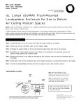
Unscrew, cut off, or break (plastic) shipping screws that mount the speaker to the bridge support. Discard any packing
material.
2
Remove ceiling tile from ceiling and place on floor or over large trash can (provides support and saves clean up time).
Place the ceiling tile with the finished position side facing up.
3
Using the bridge support as a template, mark a square opening in the
ceiling tile as shown in the illustration. Remove the bridge support and
cut out the square with a utility
knife.
4
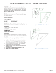
Turn ceiling tile over so the unfinished side is facing up. Replace bridge
support over cutout. Bend tabs (8)
into cutout to prevent sliding.
Typical 2' x 4'
ceiling tile
Issue 1, October 1999
54-2016-01 Printed in USA 9910
Page 1 of 4
© 1999 Bogen Communications Inc. All rights reserved.
Specifications subject to change without notice.
Select
Code:
701-000-014
5
Note: This step covers the backbox (optional) installation. Skip this step and proceed to step 6 if you are not installing a
backbox.
Punch out the knock-out in the backbox, and feed speaker wire through hole. Position the backbox onto the bridge support as shown and use horseshoe tabs to secure it into place.
6
Page 2 of 4
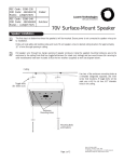
Place the ceiling tile (with
attached speaker support bridge)
back into its ceiling position.
Ensure speaker wires are pulled
to tile location.
7
The next step is to attach the speaker wires to the appropriate tap terminals located on the back of the speaker. Note: Use
22 AWG shielded, twisted pair on all wire runs. Com Code: 401882956. Pec Code: 2734-SPK. Connect speaker wire shield
to the ground (GND) terminal of the amplifier's output. Carry the ground through all speaker cables by tying the shields of
the speaker cables together in a "daisy chain" fashion. Do not connect the shield to the speaker itself. The shield is
only connected at the amplifier end and simply floats.
Note: The speaker will also work perfectly well with these connections reversed. However, reduced low frequency response
may result.
Use the appropriate instructions below (7a for voice coil speakers, or 7b for 70V round speakers).
7a
7b
Voice Coil Speaker
70V Round Speakers
Note: With 70V speakers, select the lowest tap setting (1/8W or 1/4W) before testing the speakers. This ensures that
nobody will be "blasted" when a page is made for the first time.
Tap Settings (70V Systems)
Common
Wire to:
Signal
Wire to:
dB
Out
Com
1/8W
86
Com
1/4W
89
Com
1/2W
92
Com
1 W
95
2.5W
98
Com
Page 3 of 4
8
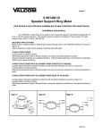
Mount the speaker assembly to the bottom surface of the ceiling tile. Secure with four mounting screws and J-nuts as
illustrated.
Mounting Round Speaker Assembly
Note: If a backbox has been installed,
speaker assemblies still mount as shown.
9
Use a screwdriver to turn the attenuator (located in the center of the speaker grille) to the fully clockwise position.
Make a test page and adjust the attenuator and tap settings as follows:
a) If page is too loud, turn the attenuator counterclockwise until desired level is attained.
b) If page is not loud enough, move the signal wire to the next higher tap setting and retest. Continue until the
appropriate tap setting is reached and use the attenuator to make fine adjustments.
Note: Final testing and adjustments should always be made at normal building sound levels.
Page 4 of 4