1
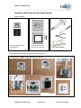
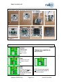
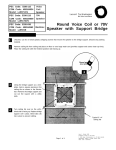
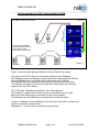
Rako Controls Ltd
INSTALLING WALLPLATES TO RAKO WIRED SYSTEM
A SIMPLE INSTALLATION.
Internal
RJ45 RAK4 cables
230v ac
Lighting Circuits
In this system Wallplate 1
and RAKLink are at end of
CAT5 cable so need
Termination Jumpers fitted
Cat5 data cable
RAKLink
Wallplate 1
Wallplate 2
Wallplate 3
Figure 1
Wallplate 4
Figure 1 shows a simple lighting installation using the Rako Wired system.
The system uses CAT5 cable to provide power and data to the Wallplates.
The Wallplate power is provided by a power supply that is fitted inside the RAKLink.
When a Wallplate button is pressed it sends commands to the RAKLink.
The RAKLink decides to which RAK4 channels the commands should be sent.
The RAKLink connects to the RAK4’s through RJ45 cables which are electrically
separate from the CAT5 cabling.
The CAT5 cable, Wallplates and RAKLink form a Data Network.
The network is a single cable to which devices are attached along it’s length.
Each end of the cable must be terminated to make it work properly.
The Wallplates and the RAKLink are provided with termination jumpers.
In figure 1: Wallplate 1 and the RAKLink are at each end of the cable, so these must
have their termination jumpers fitted.
Wallplates 2, 3, 4 must not have termination jumpers fitted.
Wallplate WCM070.doc
Page 1 of 3
Issue B. Nov 2009
Rako Controls Ltd
Installing a Wall Plate onto the Wired System
Items required:
Button Module Electronics
(eg WCM-070)
Cover Plate & Fixing Kit
(eg WVF-070 or WLF-070)
Tools (not included)
Figure 2
Fit the wallplate as shown in figure 3 or figure 4 below:
Using WVF series Flush Mounted Plate kit
Backbox minimum 35mm deep
Strip outer insulation from CAT5 cable
Follow the
colour coding
written on the
circuit board
SET THE
TERMINATION
JUMPERS
Punch down
cables using
correct
colours
Use cable ties to hold CAT5
cable to the plastic housing.
Prevents cables being ripped
from connector.
Wallplate WCM070.doc
Figure 3
Page 2 of 3
Issue B. Nov 2009
Rako Controls Ltd
Using WLF series Screwless Flush Mounted Plate Kit
Backbox minimum 35mm deep
Strip outer insulation from CAT5 cable
Follow the
colour coding
written on the
circuit board
SET THE
TERMINATION
JUMPERS
Use cable ties to hold CAT5 cable
to the plastic housing. Prevents
cables being ripped from
connector.
Punch down
cables using
correct
colours
Figure 4
Fit Mounting Frame to backbox
Plug on Control Module
Clip on Faceplate to finish
Fit Termination Jumpers to Wallplate when it is fitted at end of Data Network
Figure 5
UNTERM
Wallplates which
are not at end of
line (2, 3, 4 in
figure 1) set like
this.
TERMINATION JUMPERS ON
WALLPLATES
TERM
Wallplate at end of line
(1 in figure 1) set like
this
STAR
TERM
This setting used only if a
RAKO STAR WIRING box is
fitted to the system.
See Star Box User Manual
for details
Wallplate WCM070.doc
Page 3 of 3
NOTE: Devices are supplied
unterminated with jumpers in
positions as above
Issue B. Nov 2009