1
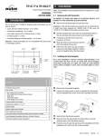
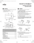
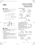
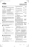
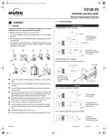
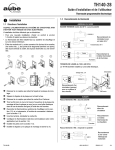
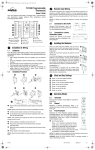
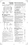
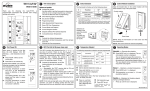
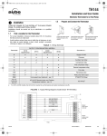
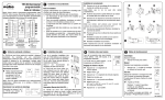
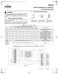
400-147-010-C (TH147_TH148 NP Aube) ENG.fm Page 1 Monday, November 27, 2006 10:41 AM
TH147 & TH148LE
Electronic Thermostats
Installation
and User Guide
Note: The installation must be performed by an electrician or a qualified installer.
2.1 Removing the Old Thermostat
IN ORDER TO AVOID ANY RISK OF ELECTRIC SHOCK, CUT
POWER TO THE HEATING/COOLING SYSTEM.
1. Introduction
n
The TH147 and TH148LE thermostats can be used to control:
Remove the old thermostat to access the wires.
Attention: If the old thermostat was mounted onto an electrical box,
it might have been powered by 120/240 volts. In this case, the
TH147 or TH148LE thermostat cannot be used.
• a gas, fuel oil or electric furnace - 2 or 3 wires
• a central air conditioner - 2 or 3 wires
• a hot water system with or without pump - 2 wires
• a millivolt system - 2 wires
• a central heating and cooling system - 4 or 5 wires
Attention: These thermostats are not compatible with heat pumps
or multi-stage systems.
Display
2. Installation
Adjustment
buttons
o
Identify and label each wire (with the corresponding letter on
the wire terminal) and remove it from its terminal.
p
If necessary, strip the end of each wire
(maximum of 6 mm).
q
Wrap the wires around a pencil to prevent
them from falling into the wall.
r
If the hole in the wall is too big, insulate it
using a non-flammable material in order
to avoid air draughts behind the thermostat.
2.2 Installing the New Baseplate
Backlight
button
Functions
TH148LE
Fan operating
mode selector
TH147
System operating
mode selector
For a new installation, choose a location approximately 1.5 m
(5 feet) above the floor and on an inside wall. Avoid draughty
areas (top of staircase, air outlet, etc.), dead air spots (behind
doors), direct sunlight or areas near concealed pipes or chimneys.
Heating/cooling control
X
X
Fan control
X
X
Programmable cycle lengths
X
X
Temperature display in °C or °F
X
X
Backlit display
X
X
Battery replacement indicator
X
X
Unoccupied mode activated remotely (requires Aube’s CT240)
X
Interchangeable faceplates (titanium, charcoal & taupe)
X
TH147 and TH148LE
n
o
Remove the thermostat faceplate.
p
q
Gently tilt the thermostat upwards.
r
Pass the wires through the opening of the baseplate and fix the
baseplate to the wall using the screws provided.
Loosen the locking screw in order to separate the thermostat
from its baseplate (the screw cannot be completely removed).
Mark and bore the appropriate mounting holes (or use the
existing holes). Insert the plastic anchors.
400-147-010-C
27/11/06
1/4
400-147-010-C (TH147_TH148 NP Aube) ENG.fm Page 2 Monday, November 27, 2006 10:41 AM
2.3 Connecting the Thermostat
2.3.5 4-wire Heating and Cooling
Refer to the following table for matching the wire labels with the
thermostat terminals.
Terminals
Description
Wire labels
Rh
Heating power supply
Rh, R, 4, V
Rc
Cooling power supply
Rc, R
W
Heating signal
W, W1, H
Y
Cooling signal
Y, Y1, M
G
Fan
Un / Un
Heat relay
Cool relay
Fan relay
G, F
Input for a remote control device (TH148LE only)
-
2.3.6 5-wire Heating and Cooling
Note: Do not connect wires identified as C, X or B. Wrap the bare
end of these wires with electrical tape.
n
Loosen the screws of the terminal
block and insert the wires in the
respective terminals.
o
Tighten the screws.
Fan relay
Heat relay
Cool relay
Note: Remove the red jumper wire between terminals Rc and Rh.
Important: The red jumper wire between Rh and Rc terminals must
be removed in a 5-wire installation.
2.3.1 2-wire Heating
2.4 Remote Control Input (TH148LE only)
The TH148LE thermostat has an input to which a CT240 telephone
controller (optional) or any other remote control system (e.g., home
automation) can be connected. When the input receives a
12-VDC signal, the thermostat switches from its current mode to the
unoccupied mode and vice versa when the signal is removed.
The unoccupied mode can be used to re-adjust the temperature to
save energy when you are away for an extended period of time. To
set the unoccupied mode temperature, see section 4.
Heat relay
2.3.2 2-wire Cooling
2.4.1 Connecting to CT240
Connect TH148LE terminals UN and UN to
CT240 terminals A and C (no polarity to observe).
Cool relay
2.4.2 Connecting to a Home Automation System
Connect TH148LE terminals UN and UN to a 12VDC circuit as shown.
2.3.3 3-wire Heating
2.5 Setting JP2 Jumper
Heat relay
Fan relay
The jumper specifies how the fan will operate when it is placed in
automatic mode.
JP2 jumper
HE
Place the jumper in this position if you
have an electric furnace.
HG
Leave the jumper in this position if you
have a gas or fuel oil furnace.
2.3.4 3-wire Cooling
Cool relay
Fan relay
TH147 and TH148LE
400-147-010-C
27/11/06
2/4
400-147-010-C (TH147_TH148 NP Aube) ENG.fm Page 3 Monday, November 27, 2006 10:41 AM
2.6 Installing the Batteries
3.3 Viewing and Setting the Ambient Temperature
The ambient temperature is normally displayed. To view the setpoint, press once on one of the
buttons. The setpoint is displayed for 5 seconds and is indicated by the
symbol on the
display. During the setpoint display, press one of the
buttons to
change it.
3.4 Backlight
The display illuminates for 12 seconds when the backlight button or
either of the
buttons is pressed.
n
o
p
Gently pull out the battery cover.
Install the batteries as shown. Observe the polarity.
Reinstall the battery cover. You will hear a clicking sound.
When batteries are installed for the first time, the thermostat performs a sequence of tests for about 5 seconds.
Afterwards, the thermostat displays the ambient temperature. It is
normal that the displayed temperature will be higher than the ambient temperature if you hold the thermostat in your hands. It will
return to normal shortly after the thermostat is installed on the wall.
By default, the setpoint is 21°C (70°F).
2.7
Completing the Installation
3.5 Unoccupied Mode (TH148LE only)
To place the thermostat in unoccupied mode, see section 2.4. In this
mode, the
icon is displayed and only the
buttons work to
allow a temporary bypass.
3.5.1 Temporary Bypass (TH148LE only)
If you modify the setpoint (using the
buttons) when the thermostat is in unoccupied mode, the thermostat temporarily bypasses
the setpoint of the unoccupied mode. The new setpoint will be maintained for 2 hours, then the thermostat will return to the setpoint of
the unoccupied mode. The
icon flashes during the bypass.
3.6 Low-Battery Indicator
An icon appears when the batteries need replacement.
This icon will flash for 120 days, then the thermostat
will cut power to the heating/cooling unit. The icon disappears once the batteries are replaced and the thermostat reinstalled on its base.
n
Once the baseplate and the batteries are installed, mount the
thermostat on the baseplate.
o
Secure the thermostat using the locking screw and install the
faceplate.
p
Apply power back to the system.
Warning: Before removing the batteries, place the
system switch on the thermostat to Off. Otherwise, the
heating/cooling unit might still be running even after
the batteries are removed.
Note: The thermostat settings are not erased when
the batteries are dead or removed.
3. Basic Functions
3.1 System Operating Mode
Use this selector switch to set the system to heating
mode (HEAT), cooling mode (COOL), or Off.
Note: When you place the thermostat in cooling mode,
you might need to wait up to five minutes before cooling can start.
This delay is a safety feature for the compressor. The
icon will
flash on the screen until cooling can start again.
3.2 Fan Operating Mode
Use the selector switch to set the fan to automatic
mode (AUTO) or continuous mode (ON).
Note: This switch is not used in a 2-wire installation as
the fan is not connected to the thermostat.
AUTO
ON
The fan operates only when heating or cooling is activated.
The fan operates continuously.
TH147 and TH148LE
400-147-010-C
27/11/06
3/4
400-147-010-C (TH147_TH148 NP Aube) ENG.fm Page 4 Monday, November 27, 2006 10:41 AM
4. Configuration Menu
DISPLAY
DESCRIPTION
6. Warranty
DEFAULT
OPTIONS
Temperature display
°C
°C or °F
Unoccupied mode setpoint - heating (TH148LE only) 1, 2
10°C
(50°F)
5°C to 28°C
(41°F to 82°F)
Unoccupied mode setpoint - cooling (TH148LE only) 1, 2
35°C
(95°F)
15°C to 35°C
(59°F to 95°F)
4
2, 3, 4, 5 or 6 3
4
4
Heating cycles per hour 2
Cooling cycles per hour
2
2, 3, 4, 5 or 6
1
To enable the Unoccupied mode, see section 2.4.
Use the system mode selector to switch the display between the heating parameter and the cooling parameter.
3
For optimal heating control, use the setting that matches your system as follows:
2=30 min (steam, gravity), 3=20 min (hot water, 90%+ high-efficiency furnace),
4=15 min (gas or oil), 5=12 min (alternate setting for gas or oil), 6=10 min (electric).
4
The corresponding cycle lengths are: 2=30 min., 3=20 min., 4=15 min., 5=12 min.,
6=10 min.
2
n
To access the configuration menu, press the backlight button
for 3 seconds.
o
To go to the next parameter (menu item), briefly press the
backlight button.
p
q
r
To modify a parameter, press
.
Repeat steps 2 and 3 if necessary.
Press the backlight button for 3 seconds to exit the configuration menu.
5. Technical Specifications
Power supply: 2 AA batteries
Maximum load: 1 A @ 24 Vca per output
Unoccupied load: 12 VCC / ± 10% / 20 mA
Setpoint range (heating): 5 to 28°C (41 to 82°F)
Aube warrants this product, excluding battery, to be free from
defects in the workmanship or materials, under normal use and service, for a period of one (1) year from the date of purchase by the
consumer. If at any time during the warranty period the product is
determined to be defective or malfunctions, Aube shall repair or
replace it (at Aube's option).
If the product is defective,
(i)
return it, with a bill of sale or other dated proof of purchase, to
the place from which you purchased it, or
(ii) contact Aube. Aube will make the determination whether the
product should be returned, or whether a replacement product
can be sent to you.
This warranty does not cover removal or reinstallation costs. This
warranty shall not apply if it is shown by Aube that the defect or malfunction was caused by damage which occurred while the product
was in the possession of a consumer.
Aube's sole responsibility shall be to repair or replace the product
within the terms stated above. AUBE SHALL NOT BE LIABLE FOR
ANY LOSS OR DAMAGE OF ANY KIND, INCLUDING ANY INCIDENTAL OR CONSEQUENTIAL DAMAGES RESULTING,
DIRECTLY OR INDIRECTLY, FROM ANY BREACH OF ANY WARRANTY, EXPRESS OR IMPLIED, OR ANY OTHER FAILURE OF
THIS PRODUCT. Some provinces and states do not allow the
exclusion or limitation of incidental or consequential damages, so
this limitation may not apply to you.
THIS WARRANTY IS THE ONLY EXPRESS WARRANTY HONEYWELL MAKES ON THIS PRODUCT. THE DURATION OF ANY
IMPLIED WARRANTIES, INCLUDING THE WARRANTIES OF
MERCHANTABILITY AND FITNESS FOR A PARTICULAR PURPOSE, IS HEREBY LIMITED TO THE ONE-YEAR DURATION OF
THIS WARRANTY. Some provinces and states do not allow limitations on how long an implied warranty lasts, so the above limitation
may not apply to you.
This warranty gives you specific legal rights, and you may have
other rights which vary from province or state to another.
Setpoint range (cooling): 15 to 35°C (59 to 95°F)
Display range: -10 to 50°C (14 to 122°F)
Storage temperature: -20 to 50°C (-2 to 122°F)
Temperature display resolution: 0.5°C (1°F)
Accuracy: ± 0.5°C (1°F)
Cycle length: 10, 12, 15, 20 or 30 min. (programmable)
Compressor short-cycle protection (minimum off time): 5 minutes
Dimensions: 127 mm x 75 mm x 28 mm (5 in. x 3 in. x 1 in.)
7. Service
For any questions regarding the product installation, operation or
warranty, contact us at:
705 Montrichard
Saint-Jean-sur-Richelieu, Quebec
J2X 5K8
Canada
Tel.: (450) 358-4600
Toll-free: 1-800-831-AUBE
Fax: (450) 358-4650
Email: [email protected]
For more information on our products, visit us at
www.aubetech.com
TH147 and TH148LE
400-147-010-C
27/11/06
4/4