1
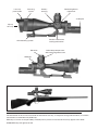
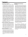
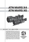
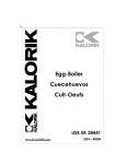
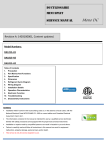
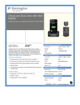
10x65Z ARMY MILDOT u s e r ` s g u i d e AMERICAN TECHNOLOGIES NETWORK CORP. Lens cap push-button Focusing system Reticle brightness adjustment Battery housing ±5 Diopter Flip-up lens cap ATN mounting system Elevation Fixation screw of the locking mechanizm Bullet drop compensator with interchangeable cams Windage The information in this manual furnished for information use only, is subject to change without notice, is not to be construed as a commitment by ATN Corp. ATN Corp. assumes no responsibility or liability for any errors or inaccuracies that may appear in this book. ©2003 ATN Corp. All right reserved. APPLICATION The ATN 10x65Z-Army Mil-Dot is not an evolution but a revolution, not an improvement, but a breakthrough. For years the best names in optics were aspired to produce a balanced large aperture tactical scope. Large aperture renders into large Exit Pupil. Large Exit Pupil means longer operating hours and better performance in low light conditions and in “stressed” environment. Nevertheless, the “let’s get a Big Hunting scope and put a Mil-Dot in it and call it “Tactical”” approach always led to a problem with uncomfortably high mounting. The new ATN 10x65Z-Army Mil-Dot prismatic design solves all the problems, and allows a sniper to use a scope with 65mm aperture that sits closer to the barrel than a standard 40mm scope. With a sharp crisp image, workable size, high durability and with an abundance of features like illuminated Army Mil-Dot reticle, interchangeable Bullet Drop Compensator for five different calibers, “will-not-bump” eye relief and parallax adjustment the ATN 10x65Z is a standard not an option for LE marksmen and military sniper alike. FEATURES • Magnification: Fixed 10X. • Objective Aperture: 65mm. Construction/Materials: Composite structure using aircraft aluminum alloy, high-carbon steel alloy and titanium inserts with 2mm wall minimum. • Optics: Patented prismatic design; highest grade heavy glass; all elements and surfaces are multicoated; developed with latest optical software and manufactured with topmost tolerances. • Reticle: Standard Army Mil-Dot; edged prismatic/optical glass sandwich; Illuminated with 12 rheostat positions; visible and operational if illumination is turned off; standard side locking mechanism. • Point of impact: Always on the center of the field of view. • Field of View @ 10X: 3 o - 17ft at 100 yards (5.6 meters at 100 meters), - 170ft at 1000 yards (56 meters at 1000 meters). • Bullet Drop Compensator: Build in; standard for .223, .300, .308, 30-06, .50BMG calibers; with 200 yard zero-in and up to 1000 yards and up to 1800 yards for .50BMG. • Parallax adjustment: from 30 yards to infinity. • Exit Pupil @10X: 6.5mm. • Eye Relief: 3” (75mm); sufficient for operation with large calibers and/or protective glasses or gas mask. • Target knobs: Included. • Environment: waterproof up to 66 feet (20 meters) up to 1 hour; fog-proof and nitrogen purged. • Diopter Adjustment: +/- 5. • Adjustment: 1/8 MOA per click; - with 950 clicks, 9.5 revolutions with 100 clicks per revolution and 120 MOA of total elevation adjustment and BDC included; - with 475 clicks, 4.75 revolutions with 100 clicks per revolution and 60 MOA of total elevation. • Power source: 3V; standard watch battery type CR2032 or CR2432; with minimum 100 hours of continuous use. • Length: 14” (350mm). Weight: 53oz (1,6 kilo) with built-in mounting system. • Sunshade: Standard built-in. • Front Lens Cover: Push-button; standard built-in. • Mounting system: Built-in monorail with ejection cavity and thumb-screws for tool-less mounting on NATO standard Picatinny rail or quality Weaver bases. 2 OPERATING MOUNTING 1. Slightly loosen the fixing screws on the weaver rail built into the scope. 2. Place the scope on the dovetail mount of the fire arm making certain that the mount aligns with the receptor attachment screw groove. Adjust as necessary. 3. Tighten the fixing screws. NOTE: Receptor attachment screws may need to be tightened after continuous shooting. The ATN Mounting System allows to change the position of the riflescope flexibly on the weapon in relation to a shooter in combination with the fixed positions already available on the weaver rail. For this purpose in the base of the mounting bracket there is a rail with a fixing projection. There are 2 grooves in the mounting bracket for mounting this rail. Besides it is possible to change the position of the riflescope additionally by 1/3 of inch. For doing this one needs to about-face the rail. Fixing projection Screws Threaded aperture Rail To change the position of the riflescope on the weaver rail additionally follow the steps mentioned below: CAUTION: Viewing the sun can cause serious eye injury, never look at the sun with this product or even the naked eye. If the reticle is not sharply defined instantly, turn the eyepiece (either direction) a few turns. Quickly glance through the scope again. If the focus has improved, but is still not perfect, continue focusing. If the focus condition become worse turn the focus the opposite direction. Next, focus the front lens until the image and the grain are both sharp. NOTE: The front lens should be readjusted as you view objects at different distances, the diopter should not be adjusted. LOCKING MECHANISM There is a locking mechanism with fixation screw for windage/elevation adjustment and zeroing mechanism. Slightly loosen the fixation screw before zeroing or windage/elevation adjustment . 1. Unscrew the two screws, which attach the rail to the mounting bracket. 2. Take the rail out of the groove. 3. About-face the rail in case of necessity. 4. Place the rail into another groove. 5. Fix the rail with the two screws. NOTE: If the rail is not taken out easily, screw up tight one of screws into the threaded aperture in the middle of a fixing projection of the rail. Continue rotation of the screw. Thus the screw will push out a rail from a groove. FOCUSING While holding the scope about four inches from your eye, quickly glance through the eyepiece at a featureless, flatly lit bright area such as a wall or the sky. 3 Fixation screw After zeroing or windage/elevation adjustment turn the fixation screw clockwise, to lock the adjustment mechanism. WINDAGE AND ELEVATION The vertical and horizontal adjustments for the 10x65Z can be achieved by turning the elevation and windage adjustment mechanisms (remove dust caps first). Each click equals to 1/8 inches at 100 yards. When reaching the maximum of rotation do not use force. Windage Lines Bullet drop compensator 4. Turn the windage and elevation handles through the number of clicks necessary for an amendment. The number of clicks should be read from the scale with respect to the chosen line. Each graduation interval equals to 10 clicks. NOTE: Each click of adjustment changes bullet strike by the amount shown on the chart below. Windage/Elevation (inches of movement per click) Pins Turning scales Elevation ZEROING Pre-zeroing is recommended and can be done in accordance with a scope guide or owner’s instructions. CAUTION: Be sure gun is not loaded. Always use safe gun handling procedures. All shooting should be done at an approved range or other safe area. Eye and ear protection is recommended. DANGER: If you used a bore-obstructing device, remove it before proceeding. If the barrel has-been drilled for a mount, check that the screws do not protrude into the bore. Do not fire live or even blank ammunition with an obstructed barrel. An obstruction can cause serious damage to the gun and possible injury to you and others nearby. Set the shooting distance on the compensator’s scale. From a steady position, fire three rounds at a target. Observe the impact errors and estimate the correction value. Adjust windage and elevation handles as needed to correct aim. 1. Remove the dust caps from the top of the windage and elevation adjusting handles. 2. Choose one of the lines as regard to which you can take readings more conveniently. 3. Rotating the scale by protrusive pins set zero of the turning scale just opposite the chosen line. 100 Yards - 1/8” 200 Yards - 1/4” 300 Yards - 3/8” 400 Yards - 1/2” 600 Yards - 3/4” 800 Yards - 1” 1000Yards - 1 1/4” When you have finished adjustment of fire, recap windage and elevation mechanisms. ELECTRONIC RETICLE Your scope has an electronic reticle. There are 11 degrees of illumination. The rheostat is the knob located at the back of the scope. It is labeled with numbers OFF through 11. When the rheostat is set at OFF you will see a black etched reticle. The reticle will light up red electronically as you rotate the rheostat through the numbers, 11 being the brightest. RANGEFINDER RETICLE The Mil-dot reticle is used in the 10x65Z. Mil dot reticle is a reliable means of determining distances to targets, establishing leads for moving targets, and for alternate aiming points for windage and elevation holds. Dots are spaced in one mil (milliradian) increments on the crosshair. A distance to target can be calculated using the mil formula, that is based on the size of the object being targeted. Look through the scope, and bracket the object between dots. 1 mil 1 mil 4 The space between dot centers subtends one milliradian(mil). One mil. subtends 3.6 inches at 100 yards or 36 inches at 1,000 yards. To use this system effectively you must know the size of the target. By measuring the height or width of a known (or approximately known target size) in milradians using the reticles, the target distance can be calculated as follows. R = range in meters, H = target size in meters, M = mil-radians of the image size: R = 1000 * H / M Military shooters are trained to know that the common male torso is 39 inches from crotch to top of head. This is very close to exactly one meter. This formula then becomes R = 1000 / M for a one meter target size. BULLET DROP COMPENSATOR You should have zeroed your scope in at 200 yards. When shooting at longer ranges the bullet drop compensator can be adjusted for 200, 400, 600, 800 and 1000 yards (1800 yars for .50 BMG). Pending on the distance click the bullet drop compensator to the appropriate setting. This will automatically adjust your reticle for that particular distance. Your scope also comes with other cams allowing you to change your bullet drop compensator to work with the different rifles. Bullet drop compensator with interchangeable cams All of the following formula are equivalent to the one above for estimating range. R = range in meters, H = target size in inches, M = mil-radians of the image: R = 25.4 * H / M R = range in yards, H = target size in inches, M = mil-radians of the image: R = 27.78 * H / M R = range in yards, H = target size in feet, M = mil-radians of the image: R=333.3 * H / M US Army Mil-dot Reticle .1 mil USMC Mil-dot Reticle .25 mil .2 mil 1/ 4 mil 1/ 2 mil 3 / 4 mil 1 mil 1/ 2 mil CHANGING THE BULLET DROP COMPENSATOR Set the bullet drop compensator to the 200yard range). Then remove the elevation dust cover from the cam. Next you will find three small set screws on the bullet drop compensator right above the yardage numbers. Remove these screws and lift the cam off of the scope. Once you have done this select the desired caliber cam you would like to use and place this cam where you removed the previous one (make sure that a replacement cam is set to the 200-yard range. Then tighten the cam in place by putting the three set screws back. Finally replace the dust cover. 1/ 4 mil 3 / 4 mil 1 mil MAINTAINING YOUR RIFLE SCOPE Your rifle scope is waterproof and shockproof. However, you should never try to take apart or clean it internally (it will void your warranty). If your scope ever does need repairs or adjustments, it should be returned to ATN’s service department. The exposed optical surfaces will perform their best if they are occasionally wiped clean with a lens cloth or with optical quality lens paper like those for eyeglasses or 5 camera lenses. Maintain the metal surfaces of your rifle scope by removing any dirt or sand with a soft brush so as to avoid scratching the finish. Wipe down the scope with a damp cloth and follow with a dry cloth. Finally, going over the tube with a silicone treated cloth will restore luster and protect the scope against corrosion. Be careful not to touch the any of the lenses with the silicone cloth. WARRANTY LIMITATION OF LIABILITY ATN will not be liable for any claims, actions, suits, proceedings, costs, expenses, damages or liabilities arising out of the use of this product. Operation and use of the product are the sole responsibility of the Customer. ATN’s sole undertaking is limited to providing the products and services outlined herein in accordance with the terms and conditions of this Agreement. The provision of products sold and services performed by ATN to the Customer shall not be interpreted, construed. 01 regarded, either expressly or implied. as being fur the benefit of or creating any obligation toward any third party of legal entity outside ATN and the Customer: ATN’s obligations under this Agreement extend solely to the Customer. ATN’S LIABILITY HEREUNDER FOR DAMAGES. REGARDLESS OF THE FORM OR ACTION, SHALL NOT EXCEED THE FEES OR OTHER CHARGES PAID TO ATN BY THE CUSTOMER OR CUSTOMER’S DEALER. ATN SHALL NOT, IN ANY EVENT, BE LIABLE FOR SPECIAL, INDIRECT, INCIDENTAL. OR CONSEQUENTIAL DAMAGES. INCLUDING. BUT NOT LIMITED TO. LOST INCOME, LOST REVENUE. OR LOST PROFIT. WHETHER SUCH DAMAGES WERE FORESEEABLE OR NOT AT THE TIME OF PURCHASE. AND WHETHER OR NOT SUCH DAMAGES ARISE OUT OF A BREACH OF WARRANTY, A BREACH OF AGREEMENT, NEGLIGENCE, STRICT LIABILITY OR ANY OTHER THEORY OF LIABILITY. PRODUCT WARRANTY REGISTRATION In order to validate the warranty on your product, ATN must receive a completed Product Warranty Registration Card for each unit. Please complete me form below and immediately mail it to our Service Centre: ATN Corporation, 20 South Linden Ave. Suite 1B, South San Francisco, CA 94080. Products qualifying for warranty repair will be either repaired or replaced within 10 business days of receipt of merchandise unless the customer is notified otherwise. OBTAINLNG WARRANTY SERVICE LIFETIME LIMITED PRODUCT WARRANTY This product comes with a Lifetime Guarantee against defects in both materials and workmanship. In the event a defect that is covered by the foregoing warranty occurs during the applicable period stated above, ATN, at its option, will either repair or replace the product, and such action on the part of ATN shall be the full extent of ATN’s liability, and the Customer’s sole and exclusive remedy. This warranty does not cover a product (a) used in other than its normal and customary manner; (b) subjected to misuse, (c) subjected to alterations, modifications or repairs by the Customer of by any party other than ATN without prior written consent of ATN; (d) special order or “close-out” merchandise or merchandise sold “as-is” by either ATN or the ATN dealer; or (e) merchandise that has been discontinued by the manufacturer and either parts or replacement units are not available due to reasons beyond the control of ATN. ATN shall not be responsible for any defects or damage that in ATN’s opinion is a result from the mishandling, abuse, misuse, improper storage or improper operation, including use in conjunction with equipment which is electrically or mechanically incompatible with or of inferior quality to the product, as well as failure to maintain the environmental conditions specified by the manufacturer. This warranty is extended only to the original purchaser. Any breach of this warranty shall be waived unless the customer notifies ATN at the address noted below within in the applicable warranty period. THE CUSTOMER UNDERSTANDS AND AGREES THAT EXCEPT FOR THE FOREGOING WARRANTY, NO OTHER WARRANTIES WRITTEN OR ORAL, STATUTORY, EXPRESSED OR IMPLIED, INCLUDING ANY IMPLIED WARRANTY OF MERCHANTABILITY OR FITNESS FOR A PARTICULAR PURPOSE, SHALL APPLY TO THE PRODUCT. ALL SUCH IMPLIED WARRANTIES ARE HEREBY AND EXPRESSLY DISCLAIMED. To obtain warranty service on your unit, take or send the product, postage paid, with a copy of our sales receipt to our service centre, ATN Corporation at the address noted above. All merchandise must be fully insured with the correct postage; ATN will not be responsible for improper postage, or, missing or damaged merchandise during shipment. 6 For customer service and technical support, please contact American Technologies Network Corp. North American Office 20 S. Linden Ave. Suite 1B, South San Francisco, CA 94080 phone: 800-910-2862, 650-875-0130; fax: 650-875-0129 European Office phone: 44(0)870-0111286, fax: 44(0) 845-3349142 The following countries can use our toll free number 00 800 9102-8620 Austria, France, Germany, Holland, Italy, Spain, Sweden, Switzerland www.atncorp.com ©2003 ATN Corporation