1
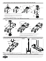
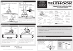
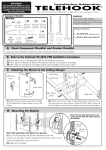
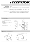
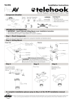
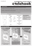
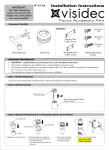
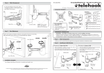
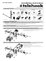
Installation Instructions
TH-3070-CT-B2B
Back to Back Accessory for TH-3070-CTL & TH3070-CTS
Component Checklist
Tools Required:
• 17mm(0.7”) Socket Wrench or Shifter
HARDWARE
M6x16mm/30mm/45mm
M4x12mm Bracket Locking Clamp Cover Clamp Cover M10
Screw (x2)
Plate (x2)
Middle
Washer
Side (x2)
Horizontal Rail
Mounting
Cable
Bracket (x2) Clip (x2)
B2B Head
Clamp Assembly
M8x15mm
Screw (x2)
Clamp Cover M10x30
Bottom
Screw
M6/M8 Washer M8x16mm/30mm/50mm
(x4 each)
Display Mounting
Screws (x4 each)
M6/M8
Spacer (x4 each)
2mm/2.5mm/5mm
8mm Allen Key
IMPORTANT INFORMATION:
! IMPORTANT - Install Telehook 3070 Back to Back Accessory as per installation instruction.
! This product is to be installed in conjunction with TH-3070-CTL and TH-3070-CTS mounts only.
! The manufacturer accepts no responsibility for incorrect installation.
Step 1. Check Components
Check you have received against the component checklist and hardware above.
Step 2. Remove the clamp parts from Head Assembly of TH-3070-CTL/CTS
1
A. Use the required 17mm Socket Wrench or Shifter to hold the nuts (item 1).
B. Use the supplied 8mm Allen Key to loosen the bolts (item 2).
C. Remove all the clamp parts items 1 to 6.
3
2
6
3
6
2
1
4
5
Step 3. Assemble the clamp parts to B2B Head Assembly
A.
B.
C.
D.
E.
1
3
2
Insert the four washers (item 6) to the four holes.
Put the clamp (item 5) in place.
Put the spacer (item 4) in place.
Attach the bolts (item 2) and nuts (item 1) with washers (item 3).
Tighten using the supplied 8mm Allen Key paired with the required 17mm
Socket Wrench or Shifter.
6
3
6
2
1
4
5
Step 4. Remove the collar from Head Assembly of TH-3070-CTL/CTS
7
9
Tightening Tool
9
8
UNLOCK
Set Screw#1
10
A. Remove the three set screws (item 7) using the 3mm Allen Key from
TH-3070-CTL/CTS.
B. Remove the set screw (item 8) using the supplied 2mm Allen Key.
C. Loosen the locking ring (item 9) using the supplied tightening tool.
D. Remove item 9 and an item 10.
E. Loosen Set Screw#1 using the supplied 2mm Allen Key to easily
remove item 11 and the another item 10.
11
Step 5. Assemble the collar to the B2B Head Assembly
9
Tightening Tool
LOCK
10
Set Screw#2
8
A.
B.
C.
D.
E.
11
Attach item 11 and an item 10 to B2B Head Assembly.
Insert and screw item 9 and the remaining item 10 to the installed item 11.
Tighten Set Screw#2 using the supplied 2mm Allen Key to fix item 11.
Tighten item 9 using the supplied tightening tool.
Insert item 8 using the supplied 2mm Allen Key to secure item 9.
Step 6. Attach to TH-3070-CTL/CTS Pole Assembly
A. Attach the B2B Head Assembly to TH-3070-CTL/CTS Pole Assembly. Completed
B. Insert the three set screws (item 7) to secure.
installation
Clamp Covers installed to the B2B
Head Assembly
TH-3070-CTL/CTS
Pole Assembly
ATTACH
7
Bottom Cover
NOTE: Please refer from step 8 until the last step of TH-3070-CTL/CTS
instruction manual to complete installation.
NOTE: The two bottom covers should be
installed with exit/entry ports as shown.
Refer to the TH-3070-CTL/CTS Installation Manual to complete installation
No portion of this document or any artwork contained herein should be reproduced in any way without the express written consent of Atdec Pty Ltd.
Due to continuing product development, the manufacturer reserves the right to alter specifications without notice. Published 09.09.12 ©