1
C amera
C amera
Wireless
Observation System
C amera C able
C amera C able
Trans mitter
Trans mitter
Page 4
Monitor/R ec eiver
Monitor/R ec eiver
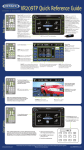
Place transmitter on trailer at window level of the tow vehicle for best reception.
P/N 37200038 6/5/07
AOM56WXSYS
M O N I T O R F E AT U R E S :
C A M E R A F E AT U R E S :
• 5.6" high performance LCD monitor with12V
accessory plug
• Built-in speaker
• Convenient front controls (power on/off, brightness
adjust
• Allows full time rear viewing while driving
• Comes with suction cup monitor mount that allows
monitor to be easily mounted to the windshield of
any tow vehicle
• Monitor can move from one tow vehicle to another
• Monitor dimensions: 5-7/8"W x 5-1/4"H x 1-1/4"D
• 12 Volt
• Infrared LED illumination for enhanced low light
performance
• Mirror image
• Locking waterproof cable connector for durability
and long life
• Non-corrosive mounting bracket
Stainless steel hardware
• Wide viewing angles
• Camera dimensions: 2-11/16"W x 1-5/8"H x 21/2"D
AOM56WXSYS PACKAGE INCLUDES: One 5.6” Color LCD Monitor with 12V Accessory Plug, One
Suction Cup Monitor Mount, One Rear Color Camera, One Cable for Trailer, Transmitter, Receiver,
Stainless Steel Hardware, Non-Corrosive Mounting Bracket.
53200 Marina Drive • Elkhart, IN 46514 • www.asaelectronics.com
Features and Specifcations Subject to Change Without Notice.
Planning the Installation
Installing the Receiver (WLO24RX)
Before you begin, consider the following points:
l
Line of Sight: For optimum reception, place the transmitter so
that it is level with the receiver/monitor in the tow vehicle,
preferably at window level, allowing the signal to transmit through
glass (see back page).
l
Accessing a Power Source: The power source you choose
must be ON for the transmitter and camera to power up.
Consider using clearance lights or running lights as a source of
power, keeping in mind that your lights will need to be on for the
power to travel to the transmitter/camera.
l
Routing Wires: When routing the camera extension cables from
the camera, choose a route that will protect the cable from sharp
objects and debris that could damage the cable.
The receiver comes pre-attached to the LCD monitor in the
AOM56WXSYS kit for easy installation. Attach the supplied suction cup
mount to the back of the receiver/monitor using the screw supplied (see
Figure 1). Place the receiver/monitor in a location that will not obstruct
your ability to safely operate and view outside your vehicle. When using
the suction cup mount supplied, choose a smooth surface area free of
texture or any film that would impede it's ability to grip firmly. The hole
pattern on the back of the receiver/monitor is a standard cell phone
mount pattern, allowing you many options. When choosing a mounting
option other than the suction cup mount supplied in the AOM56WXSYS,
choose a mounting device suitable to sustain the combined weight of the
receiver/monitor.
FIGURE 2
FIGURE 1
Installing the Transmitter (WLO24TX)
1.
2.
3.
4.
5.
Choose an appropriate location for the transmitter.
Drill a 1" hole to route the power and extension cables through.
Run the camera extension cable from the camera to the transmitter.
Run the power and ground from the power source to the transmitter.
Attach the transmitter to a clean/dry surface using the 3M adhesive
tape ring (supplied).
Wiring the Transmitter and Camera
Choosing a Transmission Channel
The transmitter and receiver can operate on one of four different
channels. The channel switches for the transmitter are located behind
the rubber plug on the bottom outside of the transmitter. The channel
switches for the receiver are located on the side of the receiver.
CAMERA EXTENSION
CABLE
To 12 Volt (+)
To Ground (–)
CAMERA
TRANSMITTER
1
2
3
4
1
IMPORTANT NOTE:
This system operates at 2.4GHz and may interfere with or be interfered
by devices that operate on the same frequency (i.e. cordless phones,
garage door openers, wireless security systems). Encountering short
periods of interference while driving is considered normal operation. If
you experience severe interference or picture distortion, change the
transmitting/receiving channel (see "Choosing a Transmission Channel).
If that does not improve the performance, look for an interference source
near the vehicle and turn it off, keeping in mind that the interference
source could be another vehicle with the same observation system.
Page 2
2
3
4
The transmitter channel and receiver channel must be set to the same
channel (1-4) to operate.
OFF
ON
1
2
3
4
Channel #1 ON
1
2
3
4
Channel #2 ON
1
2
3
4
Channel #3 ON
Page 3
1
2
3
4
Channel #4 ON