1
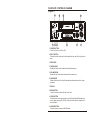
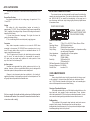
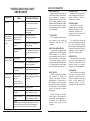
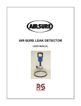
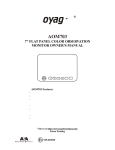
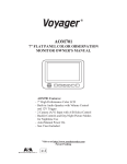
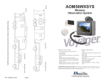
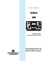
Owner's Manual
AM/FM STEREO RADIO
WITH AUTO STOP CASSETTE PLAYER
Designed Specifically for the
Marine and RV Environment
FACEPLATE CONTROLS DIAGRAM
(Figure 1)
1
10
9
2
3
8
4
7
6
5
1 POWER BUTTON
Press it to turn the unit ON or OFF
2 EJECT BUTTON
Press this button in half way to fast-forward the tape, and fully in to eject the
tape.
3 TAPE DOOR
4 TUNING KNOB
Rotate the knob to tune the desired broadcast frequency.
5 VOLUME KNOB
Rotate the knob to increase or decrease the volume level.
6 FADER KNOB
Rotate this knob to left or right for desired sound balance from front to rear
speakers.
7 DISPLAY
8 TONE BUTTON
Press this button to adjust for high or low tone.
9 LO/DX BUTTON
Press this button to change between local(LO)and distant(DX)reception.in
some cases,changing the LO/DX setting will allow clearer reception of a
desired station.
10 AM/FM BUTTON
Press this button to change AM or FM band.
1
WIRING DIAGRAM
(Figure 2)
The Mobile Electronics Company
UDIOVOX
PECIALIZED
PPLICATIONS, L.L.C.
90 DAY/12 MONTH LIMITED WARRANTY
9 PIN CONNECTORS
Antenna
BLUE
RED
BLACK
WHITE
VIOLET W/BLACK
AUT ANT
TO 12V DC (+)
POWER
TO GROUND (CHASSIS
OR 12 VDC (-)
GRAY
GREEN W/ BLACK
Front Left
Speaker
GREEN
VIOLET
VIOLET
W/BLACK
GREEN
W/BLACK
Rear Left
Speaker
2
Front Right
Speaker
Rear Right
Speaker
AUDIOVOX SPECIALIZED APPLICATION, LLC ( the company) warrants to the original retail
purchaser of this product that should this product or any part thereof, under normal use and
con ditions , be proven defective in material or workm anship within 90 days from the date of
original purchase, such defect(s) will be repaired or replaced ( at the company's option) without
charge for parts and repair labor. After the initial 90 day period and for a period of 12 months
from the date of original purchase , the Company will supply at no charge a replacement for
any defective part(s), but will charge for the labor to repair the product.
To obtain repair or replacement within the terms of this warranty, the product is to be
delivered with proof of warranty coverage (e.g.:dated bill of sale), specification of
defect(s), transportation prepaid, to an approved warranty station, or the Company
at the address shown below.
This warranty does not extend to the elimination of externally generated static or noise, to the
correction of antenna problems, to costs incurred for removal or reinstallation of the product, or to
damage to any tapes, speakers, accessories,
This warranty does not apply to any product or part thereof which , in the opinion of the company,
has been damaged through alteration, improper installation, mishandling , misuse, neglect, or
accident,THE EXTENT OF THE COMPANY'S LIABILITY UNDER THIS WARRANTY IS LIMITED TO
THE REPAIR OR REPLACEMENT PROVIDED ABOVE, AND , IN NO EVENT, SHALL THE COMPANY'S
LIABILITY EXCEED THE PURCHASE PRICE PAID BY THE PURCHASER FOR THE PRODUCT.
This warranty is in lieu of all other express warranties or liabilities. ANY IMPLIED WARRANTIES,
INCLUDING ANY IMPLIED WARRANTY OF MERCHANTABILITY , SHALL BE LIMITED TO THE
DURATION OF THIS WARRANTY . ANY ACTION FOR BREECH OF ANY WARRANTY HEREUNDER
INCLUDING ANY IMPLIED WARRANTY OF MERCHANTABILITY MUST BE BROUGHT WITHIN
A PERIOD OF 30 DAYS FROM THE DATE OF ORIGINAL PURCHASE. IN NO CASE SHALL THE
COMPANY BE LIABLE FOR ANY CONSEQUENTIAL OR INCIDENTAL DAMAGES FOR BREECH OF
THIS OR ANY OTHER WARRANTY , EXPRESS OR IMPLIED , WHATSOEVER . No person
or representative is authorized to assume for the company any liability other that expressed
herein in connection with the sale of this product.
Some states do not allow limitations on how long an implied warranty lasts or the
exclusion or limitation of incidental or consequential damages so the above
limitations or exclusions may not apply to you. This warranty gives you specific legal
rights and you may also have other rights which vary from state to state.
AUDIOVOX SPECIALIZED APPLICATIONS, LLC
23319 COOPER DR. ELKHART, IN 46514
Visit us at http://www.asaelectronics.com
7
APPLICATION NOTES
This note will discuss DC Power sources and how they relate to 12 volt
products.
General Specifications
Our general specification for the voltage range of operation is 10 to
16 volts DC .
Voltage
The voltage of a fully charged battery ( engine not running ) is
approximately 12.5 VDC. Once a load (items being powered represent the
"load" ) is applied , the voltage will drop. How much the voltage is reduced will
depend on the following:
1. Current draw (amount of amperage) The higher the draw the
greater the voltage will drop.
2. The size and length of the conductor (wire) supplying power.
Converters
Many boats incorporate convertors as a source for 12VDC when
connected to shore power (110-120 VAC).Some converters put out a very
clean DC supply where others may have a considerable amount of AC
ripple noise under maximum load.
This AC ripple noise is filtered by the boat battery when connected
into the circuit , but when the battery is disconnected the amount of
AC ripple noise can create major problems for audio products. Noise
may result and the line fuse may fail
Ignition systems
Unwanted noise generated from ignition systems used to be a big
problem. However, with more sophisticated filtering circuits designed into
audio/video products, these problems are not as wide spread
Changes in wire harnessing also has contributed to the decline of
application problems. Use the same ground point for all related products. This
will greatly reduce the potential for unwanted noise.
"We have a complete line of audio and video products specifically designed for
the Marine and RV market. Please contact ASA at www.asaelectronics.com for
a view of our on-line catalog."
6
AM ANTENNA TRIMMER ADJUSTMENT
The antenna trimmer can be accessed through the small hole behind the
cassette door (see diagram below). Tune radio to a weak station between 1200
and 1400 KHz AM ( If you cannot find a weak station in this range, tune to
any other strong station, and adjust tuning slightly off station).Adjust trimmer
for maximum volume.
FRONT VIEW OF RADIO
ANTENNA TRIMMER (NOTE:
OPEN CASSETTE DOOR TO SEE
THE ADJUSTMENT SCREW)
SPECIFICATIONS
Size:
Operating Voltage:
Output Power:
Output Wiring:
7''(W) x 2''(H) x 6-5/8''(D) 178mm x 50mm x 150mm
12VDC,Negative Ground
50Watts Max .Stereo Power
Floating Ground type designed for 4 speakers use.May
also be used with 2 speakers.
Output Impedance:
Compatible with 4 or 8 ohm speakers.
Tuning Range:
(AM)530-1710KHz
(FM)88-108MHz
Sensitivity:
(AM) less than 25uV
(FM) less than 5uV
FM Stereo Separation: More than 23 dB
Frequency Response: 50-10000Hz
Wow & Flutter:
Less than 0.3%
CARE & MAINTENANCE
Cassette
Always check that the tape is tightly wound inside the take-up spool
on the cassette. If the tape is loose,wind it with a six - sided pencil.Never
use C-120 (120 minute) cassettes in this player. Never use cassette player
when vehicle temperature is near or below freezing.
Cleaning of Tape Head & Capstan
Since tapes contain oxides, you will find a black residue builds up on the
tape head and drive capstan ( inside cassette door ). These residues
should be cleaned after 50-100 hours of accumulated tape operation .You can
use a cassette cleaning cartridge available where ever stereos are sold.
De-Magnetizing
The movement of the magnetic tape head and metal parts cause a
magnetic field to develop. We recommend you have the tape player
demagnetized at least twice annually. You can purchase an inexpensive tape
head demagnetizing tool to do this yourself.
3
TROUBLESHOOTING CHART
AM/FM RADIOS
Symptom
No Power
Power indicated;
no audio output
or very distorted
sound
Only one channel
(right or left side)
Cause
No 12VDC
Possible Solution
Check circuit fuse at source
Check in-line fuse on power
lead
Power lead disconnected
Ground connection
disconnected
No 12VDC to memory
lead(electronically
tuned units only)
Circuit fuse at source
In-line memory lead fuse
Speaker Output
shorted
Check continuity of speaker
leads to ground
Speaker out cross
channeled
Check for proper speaker wiring
Note: Radios have a sticker on
them explaining wiring color
code.
Radio Balance
Check radio function
Speaker Disconnected
Check speaker connection at
radio and/or speaker
Speaker lead shorted
or grounded
Check speaker wiring continuity
to ground w/tester or meter
Popping in one or
both channels
Speaker wiring shorted
or positive lead
grounded
Speaker terminals
grounded or shorted
Leads from speaker cone to
terminal touching metal basket
or speaker
No AM Reception
Antenna disconnected
Connect Antenna
Antenna mast grounded Check antenna or substitute with
or shorted
antenna known to be good
Antenna center lead
broken
Check antenna or substitute with
antenna known to be good
NOTE: Antenna leads can be tested with continuity or
multi-tester. Some may have electronic component
(capacitor) built in which not allow it to be tested.
4
APPLICATION NOTES
AM/FM RECEPTION
Some boats have more than one
AM/FM radio.The best way to insure
good reception is to supply a
separate antenna for each radio.
Other options available to supply
adequate AM/FM reception to these
radios are listed below, along with
some general information in regards
to radio reception.
"Y"ADAPTORS
The "Y" adaptors used to connect
one antenna to two radios will
compromise both AM and FM
reception.
AMPLIFIED AM/FM ANTENNA
A popular second antenna that
can be used is our AB-100 amplified
AM/FM antenna . It is small and
has a retractable mast that can be
mounted vertically or horizontally.
This antenna provides good FM
reception , but the AM reception will
be compromised to some degree
because of the length of the mast.
MAST LENGTH
AM/FM antennas compromise
AM reception by design . The
optimum mast length for FM is
approximately 30 inches which is
the standard for most automotive
antennas. The optimum mast length
for AM reception is over 100 inches
which is not practical for mobile
applications.
ANTENNA CABLE
Increasing the antenna lead
cable ( adding extensions ) will
reduce sensitivity of AM with
electronic tuned radios.
GROUND PLANES
Ground planes are also
important when considering
antenna performance. Most
automotive antennas are
designed to be mounted on the
metal body of the vehicle.
The metal body reflects the
signal interference generated by
the vehicle's electrical system
while it also provides the ground for
the antenna lead shield. All this is
necessary in order to maintain a
good signal, especially AM.
FM RECEPTION
FM reception can be received
with a very limited antenna and
strong local FM stations can be
received without an antenna ,
depending on the circumstances.
CONCLUSION:
AM/FM reception is subject to
the choice of an antenna and it's
application. There can also be a
variety of methods used to supply
signal to both primary and
secondary radios , but AM
performance is the ultimate "test"
Special circuitry in electronic
tuned radios or AM trimmers in
mechanically tuned radios, make
up for some of this difference in
optimum mast length for AM
reception.
5