1
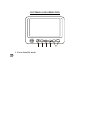
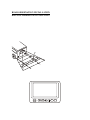
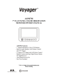
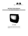
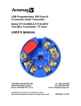
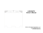
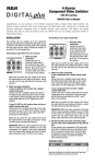
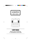
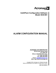
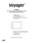
®
AOM703
7” FLAT PANEL COLOR OBSERVATION
MONITOR OWNER'S MANUAL
S
S
–
+
AOM703 Features:
– 7” High Performance Color LCD Monitor
– Water Resistant Design
– Built-in Audio Speaker with Volume Control
and 12V Trigger
– 3 Camera (A/V) Input with Source Select Control
– Backlit Controls and Day/Night Picture Modes
for Nighttime Use
– Auto/Manual Power On
– Sun Visor Included
Visit us at http://www.asaelectronics.com
Patent Pending
10R-020500
UDIOVOX
PECIALIZED
PPLICATIONS, L.L.C.
Important! – Please Read This Manual Before Installing!
Congratulations on your purchase of a Voyager AOM703 LCD Observation Monitor.
With proper installation and use, your AOM703 is designed to provide you with years
of trouble-free operation. This manual contains important information required to
properly install and operate the unit. Please read this manual thoroughly before
beginning.
All Voyager Observation products are strictly intended to be installed as a supplement
aid to standard rear-view mirror systems that may already exist in your vehicle.
Voyager observation products are not intended for use as substitutes for rear-view
mirror devices, or for any other standard motor vehicle equipment required to be
installed on vehicles by law.
While Voyager observation products contribute to improving the vehicle operator’s
field of view, these products are no substitute for proper defensive driving techniques
and observance of traffic laws and motor vehicle safety regulations.
Warnings!
Camera/Monitor Warning
1. Camera/monitor system aids in the use of, but does not replace vehicle side/
rear-view mirrors.
2. Objects in camera/monitor view are closer than they appear. When backing up,
proceed cautiously and be prepared to stop.
Installation Location
It is unlawful in most jurisdictions for a person to drive a motor vehicle equipped with
a television viewer or screen located at any point forward of the back of the driver’s
seat or in any location that is visible, directly or indirectly, to the driver while
operating the vehicle. The Voyager product is designed to be used primarily as a rear
observation device in conjunction with closed circuit cameras. In any installations
where the Voyager is used to display television broadcasts or recorded video
playback, installation location must adhere to local laws and regulations.
Tampering
To prevent electrical shock, DO NOT OPEN THE MONITOR CASE. There are
potentially harmful voltages inside the monitor. There are no user serviceable parts
inside. If evidence of tampering is detected, the warranty will be considered void.
Moisture
Your Voyager AOM703 was designed to be water-resistant. While it will withstand
short periods of exposure to moisture, this product does contain sensitive electronic
components and exposure to moisture should be limited by the user / installer. This
product is not designed for applications where constant exposure to moisture or
immersion can be encountered. This unit should NEVER be cleaned with a power
washer or used where direct power washer spray may be encountered.
2
PACKING CONTENTS:
90 DAY/ 12 MONTH LIMITED WARRANTY
SPLIT GROMMET
1” O.D. 3/16 I.D.
QTY. 1
DISTANCE MARKER
STICKER
QTY.1
4” BLACK WIRE TIE
QTY. 4
3
CONTROLS AND OPERATION
S
1
2
+
–
S
3
4
5
1. Power/Stand-By mode:
The Power / Stand-By button has two possible operation modes.
a. Manual mode - Turned on manually by the user by pressing the Power button.
b. Stand-By mode -Turned on by a stand-by trigger wire generally connected to
the vehicles 12V reverse back up lights or turn signals.
Manual Mode wiring - For manual mode operation, the AOM703 should be wired
as follows:
ACC (12V+) Red wire should be connected to the vehicles accessory feed.
GND - Black ground wire should be connected to chassis ground.
Standby Mode wiring - For standby mode operation, the AOM703 should be
wired as follows:
ACC (12V+) Red wire should be connected to the vehicles accessory feed.
GND - ground wire should be connected to chassis ground.
Standby Camera Trigger 1, Blue wire, should be connected to the reverse feed of
the vehicles back up lighting system. When triggered, the Reverse Camera
Image will be displayed on AV1.
Standby Camera Trigger 2, Brown wire, should be connected to the trigger
feed of the vehicles Left turn signal. When triggered, the Left Camera image
will be displayed on AV2.
Standby Camera Trigger 3, Green wire, should be connected to the
trigger feed of the Vehicles Right turn signal. When triggered, the Right
Camera image will be displayed on AV3.
* Note : The unit will not be turn ON when the hazard light are activated.
4
The power button features dual-illumination (bright and dim). In installations
where the unit is not wired for Stand-by operation and power is applied to the
unit, the Power Button will dimly glow when the unit is off, allowing the user
to easily find the control in low light. Illumination switches to full intensity
when the unit is turned on.
S
S
2. Source Input Select Button
This control toggles the active display image back and forth between AV1,
AV2 or AV3 inputs.
3. Day/Night Mode Button
This control toggles the unit between “Day” and “Night” LCD illumination
modes. In the “Day” mode, the LCD backlight intensity is at maximum. In
“Night” mode, the LCD backlight is dimmed to a preset level that is more
suitable for low light operation.
4. Picture Adjustment Menu Button
This control accesses an On-Screen-Display (OSD) menu for four LCD picture
adjustments (Brightness, Contrast, Color, and Tint). The first depress of the
button accesses the “Brightness” adjustment. The Volume +/- controls adjust
the level, which is indicated by the bar graph at the bottom of the screen. Each
consecutive depress of the Picture button accesses the adjustment screen for
each picture adjustment. If no buttons are pressed within 6 seconds or controls
other than the Picture and Volume buttons are pressed, the unit will exit the
Picture Adjustment mode.
–
+
5. Volume +/- Buttons
This 2-button set of controls adjusts the output volume of the built-in audio
speaker when the audio function is enabled *(see typical system connection
diagram). The “+” button increases output volume. The “-” button decreases
output volume. Volume level is indicated by the OSD bar graph at the bottom
of the screen.
These buttons also serve as adjustment controls while in the Picture Adjustment
Menu mode (see above section for details).
*Note: The AOM703 requires +12V to be applied to the “Audio Enable” trigger
input in order to activate the built-in speaker. If no audio output is heard from the
speaker regardless of the volume level adjustment, check this connection.
5
INSTALLATION INSTRUCTIONS
BEFORE YOU BEGIN INSTALLATION:
Before drilling, be sure that no cable or wiring is on the other side. Clamp all wires
securely to reduce the possibility of them being damaged during installation and use.
Keep all cables away from hot or moving parts, and electrically noisy components.
Wiring Definitions:
¡ Power connection:
Pin 1 ACC +12V (Red)
Pin 2 Standby Reverse Trigger (Blue wire)
Pin 3 Ground (Black wire)
Pin 4 Audio Trigger (White wire)
Pin 5 Standby Left Trigger (Brown wire)
Pin 6 Standby Right Trigger (Green wire)
¡
Camera A input:
Connection for camera or camera extension cable
¡
Camera B input:
Connection for camera or camera extension cable
¡
Camera C input:
Connection for camera or camera extension cable
¡
LCD panel:
13-pin DIN cable connection: junction box to monitor.
Procedure:
1. Choose the monitor, junction box, and camera mounting locations.
2. Install all required cables in vehicle. A ¾” (19mm) hole should be drilled for
passing cables through vehicle walls, barriers, etc. After the intermediate cable is
passed through the hole, install the split grommet (included). If additional cable
protection is required install convoluted tubing over the cable.
3. After cable/wiring has been routed and components are in place, temporarily make
all system connections and perform a system function check. If system does not
operate properly, see the troubleshooting section of this manual.
4. If using an optional PanaVise® stalk mount (available separately), use the
mounting template provided on page 11. Install the PanaVise® mount to the LCD
monitor using the #10 self-drilling screws (included).
**Important: Do not use screws other than those provided with the AOM703.
Void of warranty and serious product damage will occur.
6
5. Use the template provided on page 10 for proper placement of the junction box
mounting holes. Use the #8 self-drilling screws (included) to secure the junction
box in the desired location. The junction box can also be mounted using the 2”x 4”
velcro strip (included).
6. There are 2 options for connecting the LCD monitor to the junction box. If the
application is such that the monitor is in close proximity to the junction box, the
AOM703 monitor can be connected directly to the junction box. If the junction box
is mounted further from the monitor, use the 5’ intermediate cable included with the
AOM703 to connect the monitor to the junction box. If more cable length is needed,
additional 5’ lengths of the intermediate cable can be purchased. (See the accessory
list at the back of this manual for part number details.)
7. Connect the 6-pin power harness to vehicle. (See system connection illustration
page 8)
8. Plug camera extension cable (available separately) into AV1, AV2 or AV3 input
connector on the junction box. Plug observation camera into camera
extension cable.
9. Make sure all cables are routed away from hot or moving parts, and away from
sharp edges. Secure cables with wire ties.
10. For rear observation applications, range marker stickers have been included with
this product. These markers are designed to adhere to your LCD monitor and
provide a reference for gauging distance. See page 9 for illustration showing
proper use and installation of the range markers
7
8
POWER
A/V 1
A/V 2
REAR OBSERVATION INSTALLATION
DISTANCE MARKER USE/INSTALLATION
- PLACE INDICATOR MARKERS (CONE, BOX
ANY REFERENCE OBJECT HANDY) BEHIND
VEHICLE AS IN FIGURE A.
- PLACE RANGE MARKER DECALS ON SCREEN
OF MONITOR OVER IMAGE OF INDICATOR
MARKERS ON GROUND BEHIND VEHICLE, AS
VIEWED ON THE MONITOR SCREEN.
- THIS GIVES YOU A VISUAL REFERENCE OF
ACTUAL DISTANCE BEHIND VEHICLE, AS
OBJECTS ARE VIEWED.
INDICATOR
MARKERS
1FT
2FT
5FT
WIDTH OF VEHICLE
FIGURE A
S
S
–
+
FIGURE B
9
10mm
JUNCTION BOX
MOUNTING
30.4mm
60mm
10
14.8mm
10mm
5mm
9mm
155mm
175mm
TEMPLATE
PANAVISE® MOUNT TEMPLATE
(OPTIONAL ACCESSORY)
0.25
2.00
0.25
2.50
2.00
0.25
2.50
11
TROUBLESHOOTING
SYMPTOM
CAUSE
SOLUTION
No power
No +12V accessory, No
ground, mis-wired/reversed
Replace circuit fuse, monitor has protection
device built-in/reset, check ground connection,
verify power is being supplied
Video/No audio
White audio trigger wire
not powered, Volume adjust
down
Blue standby wire not powered
Connect to +12V ACC or reverse light circuit,
turn volume adjustment up
Low voltage, Brightness
adjustment down
Camera connection
Check voltage power and ground connections,
turn brightness adjustment up
Check camera input selection, connection to
camera and junction box, correct camera
connection/plugged incorrectly
+12V ACC (red wire)
connected to vehicle battery
Provide +12V ACC (red wire) power from
switched circuit
Monitor does not
activate in
Standby reverse
trigger
Negative/dark
video image
No video/no audio
Vehicle battery
drained
12
Connect to reverse circuit +12V
PRODUCT SPECIFICATIONS
LCD panel specifications:
Size/Type
7” (diagonal) /TFT LCD
Brightness
350 nit (min)
420 nit (typ.)
Contrast Ratio
200 (min)
300 (typ.)
View Angles
(@ CR³10)
Top (12 o’clock):
30°(min)
Bottom (6 o’clock): 50°(min)
Horizontal:
±50° (min)
Response Time
Rise: 12ms (typ.) ; 50ms (max)
Fall: 18ms (typ.) ; 60ms (max)
Back light Type
Back light Life
CCFL
30k hrs (min) ; 40k hrs (typ.)
Operation Temperature Range:-20°C to 65°C
Storage Temperature Range: -40°C to 80°C
Max Humidity:
100%RH
Max Vibration Force:
2.5G
Max Shock Force:
100G
Operating Voltage Range:
11VDC to 26VDC
Current Draw (typical):
50mA (Idle); 1.50A (typ) ; 1.70A (max)
Signal System:
NTSC
Video:
– Aspect Ratio:
– Input format:
– Input level:
16:9
Composite NTSC
1Vp-p into 75W
Audio
– Input level:
-10dBV nominal (317mV)
Product Weight:
3.0lbs (approximate)
Product Overall Dimensions: 7 ¾” (197mm)W x 5 ¼” (134mm)H x 1 3/16” (29.5mm)D
Visit us at http://www.asaelectronics.com
13