1
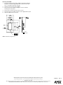
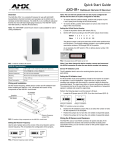
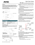
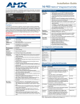
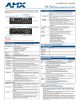
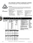
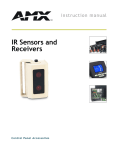
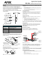
Quick Start Guide
IRX-DM+ WallMount Remote IR Sensor
Overview
The IRX-DM+ (FIG. 1) is a remote IR sensor that works with the Axcess
AXC-RCVI card, AMX Television Managers, and MX8 / MX16 Relay
Receivers to remotely control IR devices. The IRX-DM+ (FG458-10/11) is in a
UniMount enclosure that fits into most US-style single-gang enclosures. The
IRX-DM+ works with AMX 38 kHz or 455 kHz IR transmitters.
Note: The IRX-SM+ swivel-mount version is also available for wall or
ceiling installations.
Note: The unit will not operate until JP1 is configured for either 38 kHz
or 455 kHz.
•
To receive 38 kHz, position the JP1 jumper on pins 1 and 2 (closer to
the Phoenix connector).
•
To receive 455 kHz (default setting), position the JP1 jumper on pins
2 and 3 (away from the Phoenix connector).
Wiring the IR Sensors
The IRX-DM+ uses a 4-pin Phoenix connector for power and data. If the
distance between the receiver and Central Controller exceeds power
consumption limits, you can connect a local 12 VDC power supply to the
Phoenix connector.
Preparing captive wires
You will need a wire stripper and a flat-blade screwdriver to prepare the
captive wires:
IR Sensor
1.
Strip 0.25 inch (6.35 mm) of wire insulation off all wires.
2.
Insert each wire into the appropriate opening on the connector
according to the wiring diagrams in this section.
3.
Turn the flat-head screws clockwise to secure the wire in the connector.
IR Data LED
Note: Do not over-torque the screw. Doing so can bend the seating pin.
Wiring Guidelines
The IRX-DM+ requires 12 VDC power to operate properly. The power is
supplied by the AMX system's connection cable. The maximum wiring
distance between the Central Controller and the receiver is
200 feet (60.96 m).
FIG. 1 IRX-DM+ unimount IR sensor
IRX-DM+ Specifications
Dimensions (HWD):
4.68" x 2.93" x 1.14" (118.70 mm x 74.40 mm x 29.00 mm)
0.30" (7.70 mm) depth from wall surface
Available Colors:
White (FG458-10) and Black (FG458-11)
Receive Frequencies:
38 / 455 kHz (user-selectable)
Mounting:
Mounts into most US-style single-gang enclosures.
Weight:
6.8 oz. (190.4 grams)
Power Consumption:
25 mA
Connections and Wiring
Wiring the IRX-DM+ or IRX-SM+ to the AMX IR Receiver
Wire the IR sensor to the AMX IR receiver as shown in FIG. 4.
Top view
Wiring and Installation
Set the receive frequency, device number, and IR validation level before
installing the sensor. FIG. 2 illustrates the location of key components on the
IRX-DM+ circuit board.
4-pin Phoenix
Connector
4
To the external
sensor input
connector
Top view
GND
1
IN
AUX
PWR
Top view
Set Jumper JP1 to:
Position 1/2 for 38 kHz
Position 2/3 for 455 kHz
IRX-SM+ #2
or
+12 VDC IRX-DM+ #2
AUX OUT
OUT
GND
+12 VDC
AUX OUT
OUT
GND
IRX-SM+ #1
or
IRX-DM+ #1
FIG. 4 Wiring the IR sensor
Receive Frequency
Jumper Pin (JP1)
FIG. 2 Location of key components on the IRX-DM+ circuit board
You can wire up to eight IR sensors in parallel to an AXC-RCVI, AMX
Television Manager, MX8, MX16, or NI-700. For additional information, refer
to the reference guides or instruction manuals for those AMX products.
Setting the Receive Frequency
Checking IR Data Status
Use the jumper pin on the corner of the circuit board to set the receive
frequency. FIG. 3 illustrates the configuration of the jumper.
Locate the red IR Data LED on the front of the unit. Point the system's AMX
transmitter towards the sensor and press a button. The IR Data LED lights
when the unit receives data.
38 kHz
455 kHz
3
2
1
FIG. 3 Receive frequency jumper settings
If the IR Data LED on the unit does not light:
Pin 1
•
Verify that the transmit LED on the transmitter lights when you press a
button.
Pin 2
•
Check the wiring to the unit.
Pin 3
•
Verify that the transmitter frequency is properly configured.
Mounting the IRX-DM+
1.
For wall or podium mounting (FIG. 5), AMX recommends mounting the
IRX-DM+ in a standard 1-gang wallbox with a minimum internal clearance of 1 3/4" (W) x 2 5/8" (H) x 1 5/8" (D).
2.
Gently remove the bezel from the wallplate.
3.
Place the panel in the wallbox and align the screw holes with the
mounting holes on the panel.
4.
Turn the unit over and locate the Phoenix connector.
5.
Fasten the panel to the wallbox using the screws supplied with the panel.
6.
Snap the wallplate back on the bezel.
bezel
wall plate
FIG. 5 IRX-DM+ Mounting Dimensions
AMX Corporation reserves the right to alter specifications without notice at any time.
For full warranty information, refer to the AMX Instruction Manual(s) associated with your Product(s).
042-004-2749 11/04 ©2004
AMX Corporation. All rights reserved. The AMX logo is a trademark of AMX Corporation. AMX reserves the right to alter specifications without notice at any time.
3000 RESEARCH DRIVE, RICHARDSON, TX 75082 • 800.222.0193 • fax 469.624.7153 • technical support 800.932.6993 • www.amx.com
93-0458-10
REV: B