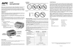
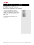
1
www.apc.com
SurgeArrest PM Series
®
PM3, PM4, and PM4Y Series
Modular Surge Protective Device (SPD)
User’s Manual
American Power Conversion Corporation
132 Fairgrounds Road
P.O. Box 278
West Kingston, Rhode Island 02892 USA
APC0212040A
SurgeArrest PM Series
®
Contents
INTRODUCTION ......................................................................................................................................... 1
Installation .............................................................................................................................................. 1
Testing .................................................................................................................................................... 1
UNPACKING AND PRELIMINARY INSPECTION
Unpacking and Preliminary Inspection ................................................................................................. 2
Storage .................................................................................................................................................... 2
LOCATION CONSIDERATIONS
Environment ........................................................................................................................................... 2
Audible Noise ......................................................................................................................................... 2
Mounting and Cabinet Data .................................................................................................................. 2
Service Clearance ................................................................................................................................... 3
Equipment Performance ........................................................................................................................ 3
Product Orientation ................................................................................................................................ 3
ELECTRICAL CONNECTIONS
Overcurrent Protection ........................................................................................................................... 3
Voltage Rating ........................................................................................................................................ 3
Terminals ................................................................................................................................................ 4
System Grounding .................................................................................................................................. 4
Parallel Connection ................................................................................................................................ 4
Wire Size & Installation Torque ............................................................................................................ 5
Disconnect Switch and Circuit Breaker ................................................................................................ 5
PM SERIES INSTALLATION INSTRUCTIONS
Installation Instructions ......................................................................................................................... 6
Configuration and Wiring Diagrams .................................................................................................... 7
OPERATION
Operation and Features .......................................................................................................................... 9
Status Panel Controls, Indicators and Alarms ...................................................................................... 9
Surge Counter Option ............................................................................................................................ 10
Dry Contacts Option .............................................................................................................................. 10
MAINTENANCE
Periodic Inspection and Cleaning .......................................................................................................... 11
Corrective Maintenance and Repairs .................................................................................................... 11
Troubleshooting ...................................................................................................................................... 11
GENERAL INFORMATION
Limited Warranty ................................................................................................................................... 17
Technical Support .................................................................................................................................. 17
TABLES
Table 1 - Cabinet Dimensions and Weight ............................................................................................ 2
Table 2 - Voltage Rating and Service Type (by Model) ........................................................................ 4
Table 3 - DB-9 Pin Configuration ......................................................................................................... 10
Table 4 - Replacement Parts List ........................................................................................................... 16
i
SurgeArrest PM Series
®
Contents
FIGURES
Figure 1 - Typical Parallel Connections ................................................................................................ 4
Figure 2 - Basic PM3 and PM4 Configuration with Disconnect Switch Option ................................ 5
Figure 3 - Basic PM3 and PM4 Configuration and Wiring Diagram .................................................. 7
Figure 4 - Basic PM4Y Configuration and Wiring Diagram ............................................................... 8
Figure 5 - Status Panel with Surge Counter Option ............................................................................. 9
Figure 6 - Troubleshooting Flowchart ................................................................................................... 12
Figure 7 - Display Board Locator Diagram .......................................................................................... 13
Figure 8 - Diagnostic Board Locator Diagram ..................................................................................... 14
Figure 9 - Surge Module Removal and Replacement ........................................................................... 15
ii
INTRODUCTION
Thank you for choosing the APC SurgeArrest PM3, PM4, or PM4Y Series Surge Protective Device.
The APC modular Surge Protective Device (SPD) is a high quality, high energy surge attenuation system that has been designed
to protect sensitive equipment from damaging transient voltage surges. Proper installation is imperative to maximize the surge
suppressor’s effectiveness and performance.
Read and understand all information contained in this manual prior to installation. This manual is to be used as a guide for
installing the device. The procedures contained in this manual are not intended to supercede local or national electrical
codes. Check all applicable electrical codes to assure compliance. In all instances, local and/or national electric code
requirements are to be followed.
This device must be installed by a licensed electrician. The electrician should follow the steps outlined in this manual to
insure a proper installation. A copy of the installer’s invoice detailing the installation of this device is required in order to
obtain warranty service for the device.
The APC PM Series modular product line is a parallel SPD designed for service entrance and downstream panelboard
applications.
The PM Series has one or two modules per phase and is available with a 120kA or 160kA per phase rating. All APC products
are extensively tested according to industry standards as set both by IEEE C62.41 and C62.45, for Categories A, B, and C,
and are listed by UL 1449 Second Edition, and UL 1283. The connection method of these devices may require several feet of
wire. Increased lead length adversely affects clamping voltages.
Save this manual! It includes instructions regarding the product warranty and replacement parts.
!
DANGER
HAZARD OF ELECTRIC SHOCK, BURN, OR EXPLOSION.
•
Turn off all power supplying this equipment before working on or
inside equipment.
•
Please read the following installation and testing warnings.
INSTALLATION
Bonding and Grounding Hazard: During installation into an electrical system, SPD’s must NOT be energized until the
electrical system is completely installed, inspected and tested. All conductors must be connected and functional, including
the neutral (if required). The voltage rating of the device and system must always be verified before energizing the SPD.
Failure to follow these guidelines can lead to abnormally high voltage being applied to the SPD. This may cause the SPD to
prematurely fail or significantly shorten the effective life. The warranty does not cover an incorrectly installed device.
TESTING
High Voltage Testing - DO NOT HI-POT TEST
Any factory or on-site testing that exceeds the normal operating voltage such as high-potential insulation testing, or any
other tests where the suppression components will be subjected to voltages higher than their rated “turn on” voltage must be
run with the suppressor disconnected from the power source. For 4-wire TVSS devices, the neutral connection at the TVSS
must also be disconnected prior to performing high-potential testing and then reconnected upon completion of the test.
Failure to disconnect this surge suppression device and its associated suppression components during elevated voltage testing
will result in damage to the suppression components and/or other electronic components.
Page 1
Unpacking and Preliminary Inspection
• Inspect the entire shipping container for damage or signs of mishandling before unpacking the unit.
• Remove the cardboard packing and further inspect the unit for any obvious shipping damages.
• If damage found is a result of shipping or handling, immediately file a claim with the shipping company and
forward a copy to APC.
Storage
The unit should be stored in a clean, dry environment. Storage temperature is -40o C (-40o F) to +60o C (+140o F). Avoid exposing
the unit to areas of high condensation. All of the packaging materials should be left intact until the unit is ready for
installation. If the unit has been stored for an extended period of time, it may be necessary to clean the unit and make a
complete inspection of the unit prior to installing and placing into service.
LOCATION CONSIDERATIONS
The following paragraphs provide information and guidance about what should be taken into consideration before installing
an APC SPD.
Environment
The unit is designed to operate indoors in an ambient temperature* range of -40o C (-40o F) to +60o C (+140o F) with a
relative humidity of 0% to 95% non-condensing. The standard unit is in a NEMA Type 1 industrial use enclosure which is
intended for indoor use. Primarily, it provides a degree of protection against contact with the enclosed equipment. It should
not be installed in areas with excessive dust, flammable materials, corrosive vapors or explosive atmospheres.
*Surge Counter option/feature has an operating temperature range of -0o C (32o F) to +60o C (+140o F)
Audible Noise
The unit background noise is negligible, and does not restrict the location of the installation.
Mounting and Cabinet Data
The PM Series is designed to be wall mounted. Unit model sizes and weights are defined in Table 1.
Model Number
Table 1: PM3, PM4, and PM4Y Dimensions and Weights
Page 2
12"W x 12"H x 6.25"D
(30.48 x 30.48 x 16.13 cm)
Weight / Shipping Weight
14"W x 16"H x 6.25"D
(35.56 x 40.64 x 16.13 cm)
Weight / Shipping Weight
PMP3
23 / 25 lbs. (10.43 / 11.43 kg)
PMP3D
29 / 32 lbs. (13.15 / 14.51 kg)
PMP4
23 / 25 lbs. (10.43 / 11.43 kg)
PMP4D
29 / 32 lbs. (13.15 / 14.51 kg)
PMF3
23 / 25 lbs. (10.43 / 11.43 kg)
PMF3D
29 / 32 lbs. (13.15 / 14.51 kg)
PMF4
23 / 25 lbs. (10.43 / 11.43 kg)
PMF4D
29 / 32 lbs. (13.15 / 14.51 kg)
PML3
23 / 25 lbs. (10.43 / 11.43 kg)
PMG3D
29 / 32 lbs. (13.15 / 14.51 kg)
PML4
23 / 25 lbs. (10.43 / 11.43 kg)
PMG4D
29 / 32 lbs. (13.15 / 14.51 kg)
PMG3
23 / 25 lbs. (10.43 / 11.43 kg)
PML3D
29 / 32 lbs. (13.15 / 14.51 kg)
PMG4
23 / 25 lbs. (10.43 / 11.43 kg)
PML4D
29 / 32 lbs. (13.15 / 14.51 kg)
PML3S
24 / 26 lbs. (10.88 / 11.79 kg)
PML4DS
30 / 33 lbs. (13.60 / 14.96 kg)
PMG4S
24 / 26 lbs. (10.88 / 11.79 kg)
PMG4DS
30 / 33 lbs. (13.60 / 14.96 kg)
PML4S
24 / 26 lbs. (10.88 / 11.79 kg)
24"W x 24"H x 7"D
(61.0 x 61.0 x 17.8 cm)
Weight / Shipping Weight
PMF3S
24 / 26 lbs. (10.88 / 11.79 kg)
PML4Y/DC/DL
65 / 78 lbs. (29.45 / 35.34 kg)
Service Clearance
In addition to national and local code requirements, 36 inches of service clearance is needed at the front of the SPD.
Equipment Performance
To obtain the maximum system performance, the unit must be located as close to the circuit to be protected as possible,
minimizing the interconnecting wire length. For every foot of wire length, approximately one (1) nanosecond of turn-on/
turn-off time will be added, and approximately 175 volts (6kV/3kA, 8/20 microsecond) will be added to the clamp voltage.
For optimum transient surge protection, staged surge suppression should be implemented at the service entrance and all
other electrical connections to the building (telephone, CATV, etc.). It should also be implemented at recognized surge
generating loads within the building (arc welding rigs, large motors, switched capacitors, etc.). Additionally, it should be
implemented for sensitive electronic loads (computer equipment, facsimile machines, copy machines, solid state motor
drives, variable frequency drives, etc.). For interconnected electronic loads (via data cabling), surge protective devices should
also be utilized to protect the devices on either end of interconnecting data cables.
APC Manufactures a complete line of surge protection devices for both alternating current (AC) and direct current (DC)
applications. Contact an authorized APC reseller, or order directly from, APC at www.apc.com.
Product Orientation
To decode the Model Number and determine the unit’s configuration, locate the printed nameplate on the top of the unit.
Note: The Serial Number, Date of Manufacture, and UL 1449 Suppression Voltage Rating (SVR) are also on the unit identification nameplate. The Model Number can be decoded as follows:
• PM identifies a SurgeArrest Panel Mount product. The following letter indicates the voltage and wiring configuration of
the device.
• Following the alpha character is the number 3, 4, or 4Y. 3 and 4 indicate SurgeArrest Panel Mount units with one
replaceable module per phase, rated at 120kA or 160kA respectively. 4Y indicates a SurgeArrest Panel Mount unit with
2 replaceable modules per phase, rated at 160kA per phase.
• Following the letter designation is optional equipment, shown as: /AA = Audible Alarm, /DC = Dry Contact, /IL =
Indicator Lights, /DS = Disconnect Switch, DL = Thru-door Disconnect Switch.
Options are detailed later in this manual.
!
WARNING
VERIFY THAT ALL POWER
CIRCUITS ARE DE-ENERGIZED
BEFORE MAKING CONNECTIONS
All electrical connections should be performed by a qualified (licensed) electrician.
All wiring must comply with the National Electric Code (NEC) and applicable local codes.
ELECTRICAL CONNECTIONS
Overcurrent Protection
The Surge Protective Device (SPD) draws very little current under normal conditions and will only conduct for a brief
duration upon encountering a transient surge voltage. APC SPD’s contain UL Listed internal fusing to protect against
abnormal voltage conditions. Note: Fuses are not replaceable.
Voltage Rating
Prior to mounting the SPD, verify that the unit has the correct voltage rating by checking the nameplate voltage or model number.
The service type should match the intended power source. See Table 2 for the voltage rating and service type of the SPD.
Page 3
Table 2: Voltage Rating and Service Type (by Model)
M ode l Numbe r
Voltage Rating and Se rvice Type
PMP3, PMP3D, PMP4, and PMP4D
120/240 Volts, Single Phase
PMF3, PMF3D, PMF3S, PMF4, and PMF4D
120/208 Volts, 3- Phase, WYE, 5 Wire
PMG3, PMG3D, PMG4, PMG4D, PMG4S, and PMG4DS
277/480 Volts, 3- Phase, WYE, 5 Wire
PML3, PML3D, PML3S, PML4, PML4D, PML4S, PML4Y, and PML4DS
347/600 Volts, 3- Phase, WYE, 5 Wire
Terminals
Terminals have been provided inside the APC modular SPD units for the line (phase), neutral, and equipment safety ground
connections. Terminal wire size for all models is #8 AWG - #1 AWG. Installation torque is 65 inch-pounds.
System Grounding
An equipment grounding conductor must be used on all electrical circuits connected to the SPD. This requirement is
primarily for safety, although SPD performance is enhanced by proper grounding. Proper operation of any surge suppression
system or device depends on a proper grounding system. Incorrect grounding practices will reduce the effectiveness or
interfere with SPD system operation and performance, as well as endanger personnel and equipment. For the best performance, use a single point ground system where the service entrance grounding electrode system is connected to and bonded
to all other available electrodes, building steel, metal water pipes, driven rods, etc. For sensitive electronics and computer
systems, it is recommended that the ground impedance measurement be 25 ohms or less. When metallic raceway is used as
an additional grounding conductor, an insulated grounding conductor should be run inside the raceway. Adequate electrical
continuity must be maintained at all raceway connections. Do not use isolating bushings to interrupt a metallic raceway run.
A separate isolated ground for the SPD is NOT recommended. Proper equipment connections to grounding system and
ground grid continuity should be verified via inspections and testing on a regular basis as part of a comprehensive electrical
maintenance program.
On 4-Wire Power Systems, neutral to ground bonding should be
installed per the NEC. Failure to do so could cause equipment damage.
Parallel Connection
When making a parallel type of connection (Figure 2), the length of the wiring to the Surge Protective Device (SPD) must be
kept as short as possible to substantially enhance the performance. Long wire runs are to be avoided for the unit to perform
as intended.
To reduce the impedance the wire displays to surge currents, the phase, neutral (if used), and ground conductors are to be
routed within the same conduit and should be tightly bundled or twisted together to optimize the performance of the unit.
Sharp bends in the conductors are to be avoided.
NOTE: Safety Ground required for ALL units.
Page 4
Figure 1. Typical Parallel Connections
Wiring Size & Installation Torque
With a parallel connection, the size of the wiring to the SPD is independent of the ampere rating of the circuit to be protected.
The recommended wire size is based on the unit’s transient surge current capabilities. #6 AWG is the recommended wire size
for phase, neutral and ground conductors.
Disconnect Switch
The PM Series is designed for connection to a 30A to 60A breaker. The PM3 and PM4 Series SPDs can be equipped with an
optional internal disconnect switch (Figure 2). The disconnect switch provides a means to de-energize the entire suppressor,
to facilitate servicing of unit’s components. (See Warning regarding the Neutral when testing the distribution system).
The PML4Y/DC/DL is equipped with an internal disconnect switch with an external manual operator located on the exterior
of the enclosure. Before opening the enclosure door the external manual operator must moved to the “OFF” position. This
will de-energize the entire suppressor to facilitate servicing of the unit’s components. To re-energize the suppressor, close the
door and move the external manual operator to the “ON” position.
NOTE: A disconnect switch will add length, which increases the response time and the clamp voltage. To minimize the
additional led length and optimize performance, units are available with an optional internal disconnect switch. The disconnect switch is not a device that can be added to the unit after purchase. It must be ordered with the unit as the mounting
cabinet is larger for units having the option.
If an internal disconnect switch is to be used, the location of the SPD and the disconnect switch should be planned out
carefully to avoid excessive lead length when wiring the devices.
Figure 2: Basic PM Configuration with Disconnect Switch Option
(Daughterboard for Optional Surge Counter Shown)
!
WARNING
VERIFY THAT ALL POWER
CIRCUITS ARE DE-ENERGIZED
BEFORE MAKING CONNECTIONS
All electrical connections should be performed by a qualified (licensed) electrician.
All wiring must comply with the National Electrical Code (NEC) and applicable local codes.
**Surge Protective Devices are designed for use on the load side
of the service entrance disconnect only**
Page 5
PM SERIES INSTALLATION INSTRUCTIONS (Typical Unit - Three Phase WYE, 4 Wire, plus Ground)
This section provides basic installation instructions for the PM Series SPD. Per UL 1449 Paragraph 1.4, SPD’s “are intended
for installation on the load side of the main overcurrent protection”. Locate the SPD as close as possible to the circuit to be
protected to minimize the wire length. This will optimize SPD performance.
Note that these instruction are not intended to supercede local or national codes. The installation should be performed by a
licensed electrician. To install a PM Series SPD, refer to the diagrams on the following pages and proceed as follows:
1.
Unpack and inspect the unit for signs of damage. If the unit is damaged, contact APC Customer Service (1-800-8004APC). See Page 17 for obtaining service under the Warranty.
2.
Warning: Disconnect power while installing the SPD. Attempting to install while energized may result in death
or injury. The installation should be performed by qualified electrical personnel.
3.
Locate where the unit is to be installed. Ensure wire lengths between the SPD and the service panel are kept to a
minimum.
4.
Use an AC voltmeter to check all voltages to ensure that the proper unit has been selected. After verifying the proper
unit has been selected, remove power from the AC distribution panel.
5.
Open the door on the unit by loosening the two screws that secure the door latches in place. Slide the top latch upward
and rotate it so that it no longer secures the door. Slide the bottom latch downward and rotate it so that it no longer
secures the door.
Drill a hole large enough to allow for the installation of the correct sized UL approved conduit with anti-short bushings
(not supplied) to accommodate the wiring being installed. NOTE: In order to keep wiring length and bend radii at a
minimum, APC recommends that wiring be installed through the left side or bottom of the SPD. APC also recommends
that the hole be sealed with putty after wiring installation..
6.
7.
Drill four (4) pilot holes (mounting holes in the SPD are 5/16” in diameter) to provide for mounting of the SPD. Mount
the devices via the flanges as close as possible to the panel being protected.
8.
Connect the unit to the service panel through the UL approved conduit with anti-short busings. The connecting wires
should be twisted together or tightly bundled and kept as short as possible to enhance the performance of the SPD.
Terminal wire size is #8 AWG to #1 AWG. Torque screws to 65 inch-pounds. The recommended wire size for phase,
neutral, and ground is #6 AWG.
Connect a wire (in conduit) to the safety ground bus of the distribution panel, and to the ground connections of the SPD
as show in the diagram on the following page, and as marked on the unit. Proper grounding is essential, use a green wire
or yellow/green striped wire for the ground connection. Connect a wire (in conduit) to the NEUTRAL bus of the panel
and to the NEUTRAL connector of the SPD as marked on the unit. Use a white wire or make with a white band for
the neutral connection.
Connect a wire (in conduit) to each phase (HOT) feed on the LOAD side of the three-pole breaker. Be sure the breaker is
turned OFF prior to making any connections of any kind. If a breaker is not available, then it will be necessary to install
or connect to an existing main disconnnect switch (on the LOAD side). Disconnect switches are available from APC as
an option and must be specified at the time of purchase; the disconnect is not an “add-on” devide and may change the
size of the enclosure. Be sure the disconnect switch is open (OFF) and the power is secured before making any connnections.
Refer to the diagram on the following page and the marking on the unit when connecting the phase wires.
After all connections have been made and not hazards exist, restore power to the panel, breaker, or disconnect switch as
required. If the SPD is installed and functioning properly, the green LED indicators on the front panel display will be lit, the
mdoule LED indicators will be lit, and there will be no audible or visual alarms..
For answers to questions about installation, call APC’s Customer Service Department at: 800-800-4APC.
Page 6
Figure 3: Basic PM3 and PM4 Configuration and Wiring Diagram
(3-Phase WYE, 4-Wire, plus Ground)
Page 7
Neutral Conductor
5/16” Mounting
Hole (4 places)
Mounting Flange
(4 places)
Surge Module with
LED (9 places)
Phase C Connector
Phase A
Phase B
Connectors
Ground Conductor
Fuse
(9 places)
Disconnect
Not to exact scale. Door removed for clarity
Figure 4. Basic PM4Y Configuration and Wiring Diagram
(3-Phase WYE, 4-Wire, plus Ground)
Page 8
Operation and Features
SPD’s do not require a great deal of operator intervention after installation.
NOTE: The PM Series has a green LED for each phase which extinguishes when the module is no longer providing protection (fault condition).
All of the PM Series of SPDs contain a diagnostic circuit which monitors the suppressor status continuously and automatically. If a fault condition were to occur, the built-in front panel audible alarm will sound and a red “Service” LED will light,
indicating that the unit is in need of service by a qualified technician.
The audible alarm can be silenced by pressing the “Mute Alarm” button on the touchpad, until a qualified electrician or
service person is available to service the unit. The red “Service” LED will continue to be illuminated even though the audible
alarm has been silenced. This will continue until the fault condition has been cleared.
Each of the internal surge protection modules have a green LED that lights to signify that the module is on-line and functioning properly (the N-G module does not have an LED). In addition to module LED’s, the front panel also displays the status
of each internal module by use of diagnostically controlled green LED’s. This technique ensures that a false indication does
not occur if an LED were to burn out. A true/hard fault condition can be confirmed by having an audible alarm with the red
“Service” LED lit, as well as any module LED and front panel status LED extinguished. By utilizing all of these built in
diagnostic features, an operator can more easily determine if a hard fault exists or if a status LED is faulty. If power is applied
the SPD and one or more of the module LED’s are extinguished and any diagnostic LED on the font panel concurs with any
module LED, then the faulted module may need to be replace. Use the troubleshooting section of the manual to locate and
repair the fault.
Status Panel Controls, Indicators and Alarms
All indicators and controls are located on the front diagnostic panel (Figure 5) of the SPD unit. Each phase features a tricolor LED indicator. Green indicates correct operation. Amber indicates reduced protection. Red indicates loss of protection.
If an inoperative condition where to occur, the built-in audible alarm will sound and the red Service LED will illuminate.
This indicates that the unit needs evaluation by a qualified electrician or technician. Until a qualified person evaluates the
unit, press the Mute Alarm touchpad to silence the alarm. (The LED indicator above the Mute Alarm touchpad illuminates
when the alarm is deactivated. Normal operation occurs with the Mute Alarm LED extinguished.) The red Service LED will
remain illuminated even though the Audible Alarm has been silenced. The Test touchpad tests the red Service LED and the
Audible Alarm.
If LEDs are illuminated in a manner that suggests contradictory information, there may be an internal logic problem and the
unit needs replacement. If none of the LEDs are illuminated, the unit may not be installed correctly. Please note that the
internal storage capacitor for surge counter backup must be energized for about 15 minutes before the “count” push button
will function. If a green LED is not illuminated and is suspect of being faulty, a qualified electrician or technician may
attempt to diagnose the problem by de-energizing the unit, removing the front cover and exchanging ribbon cable leads with
another phase (if available). Upon reenergizing the SPD, the appropriate LED will illuminate if the suspect LED has failed.
If troubleshooting indicates a failed LED, please contact APC Technical Support at: 800-800-4APC.
Figure 5. Status Panel with Surge Counter Option
Page 9
Surge Counter Option
In units so equipped, the surge counter option provides a means to total the number of transient voltage surges encountered
since the counter was last reset. The surge counter circuitry includes a “supercap”. This will provide power up to four days to
retain memory should a power outage occur. NOTE: There is a 10 - 15 minute charging cycle once power is connected, before
the surge counter operates. The surge counter registers the sum of L-N and L-G transient surges. There are Count and Reset
touchpads. Pressing the Count touchpad increments the counter by one. Pressing the Reset touchpad resets the counter to
zero count.
Dry Contacts Option
The PM Series is available with optional Dry Contacts which utilize a DB-9 connector. This feature provides two sets of both
normally open (N.O.) and normally closed (N.C.) contacts through the DB-9 connector. These relay contacts can be used for
remote indication of the SPD’s operating status by changing state when there is an alarm condiiton.. Examples could include
a computer interface board, an emergency management system, etc. The relay contact pin arrangement is outlined in Table 3.
(Please note the jumpered connections. Pins 7, 8 & 9 do not represent a third set of contacts.)
For custom applications using the Dry Contacts, please note the following information:
• The Dry Contacts are designed for low voltage or control signals only.
• Maximum switching current is 1 amp.
• Maximum switching voltage is 24 volts, DC or AC.
Higher energy application may require additional relay implementation outside the PM. Damage to the PM’s relay caused by
implementation with energy levels in excess of those discussed in this manual will not be covered by warranty. If you have
design questions, please contact APC at: 1-800-800-4APC.
Table 3: DB-9 Relay Contact Pin Configuration
PIN
C O N T A C T T YP E
1
No rm al l y Cl o s e d (1)
2
Co m m o n (1)
3
No rm al l y Op e n (1)
4, 7
No rm al l y Cl o s e d (2)
5, 8
Co m m o n (2)
6, 9
No rm al l y Op e n (2)
NOTE: Pin pairs 4 & 7, 5 & 8, and 6 & 9, are connected via jumper internally.
The combined current of each pin pair may not exceed 1 Ampere.
Page 10
WARNING
•
MAINTENANCE OF THIS SURGE PROTECTIVE DEVICE SHOULD BE PERFORMED BY
QUALIFIED ELECTRICAL PERSONNEL ONLY.
•
DURING NORMAL OPERATION, HAZARDOUS VOLTAGES ARE PRESENT INSIDE THE UNIT.
•
WHEN SERVICING THIS UNIT, BE SURE TO FOLLOW ALL ELECTRICAL SAFETY PRECAUTIONS.
•
ALL POWER SOURCES TO THIS UNIT SHOULD BE LOCKED OFF BEFORE SERVICING.
THIS WILL PREVENT THE RISK OF RECEIVING AN ELECTRICAL SHOCK.
Periodic Inspection and Cleaning
Inspection of the SPD should be performed periodically to maintain reliable system performance and continued transient
voltage surge protection. While it is difficult to establish a preventive maintenance schedule because conditions vary from
location to location, inspections for trouble utilizing the on-line diagnostics should be performed on a routine basis, weekly
or monthly.
Every effort should be made to ensure that the SPD remains clean and dry. A towel may be used to wipe the exterior of the
enclosure. Avoid excess moisture and dry with a towel as appropriate.
Corrective Maintenance and Repairs
Surge Protective Devices (SPD) are designed for years of reliable, trouble free operation. Unfortunately, even the most
reliable equipment can fail.
Built-in diagnostics are an integral part of the SPD and will aid in isolating which of the protection module(s) have failed. To
keep the SPD operating at peak performance, replacement of any bad module should be performed according to surge module
removal and replacement instructions at the earliest service opportunity.
If a single module on a particular phase fails, the fuse takes the module off-line. It is recommended by APC that if a module
fails on any specific phase, that all modules on that phase be replaced at the same time, according to module removal
instructions that follow.
Standard troubleshooting procedures should be used to isolate other problems not associated with failed modules. Fee Figure
6 (Troubleshooting Flowchart) for assistance. Replace bad components with identically rated parts to continue proper operation and safety. It is very important that fuses be replaced with the exact fuse specified on the fuse replacement warning
label shipped with each unit. This label is found on the SPD mounting plane.
After all failed modules have been replaced, prior to returning power, inspect the entire SPD for other damaged components
and replace as necessary. Table 4 lists typical replacement parts.
Troubleshooting
Troubleshooting of an SPD consists of performing the sequence of steps provided in the Troubleshooting Flowchart in Figure
6. Perform the steps in this chart only to the extent necessary to clear the failt.
Page 11
Figure 6: Troubleshooting Flowchart
Page 12
WARNING
•
MAINTENANCE OF THIS SURGE PROTECTIVE DEVICE SHOULD BE PERFORMED BY
QUALIFIED ELECTRICAL PERSONNEL ONLY.
•
DURING NORMAL OPERATION, HAZARDOUS VOLTAGES ARE PRESENT INSIDE THE UNIT.
•
WHEN SERVICING THIS UNIT, BE SURE TO FOLLOW ALL ELECTRICAL SAFETY PRECAUTIONS.
•
ALL POWER SOURCES TO THIS UNIT SHOULD BE LOCKED OFF BEFORE SERVICING.
THIS WILL PREVENT THE RISK OF RECEIVING AN ELECTRICAL SHOCK.
Display Board Removal & Replacement Instructions
To remove the Display Board, refer to Figure 7 and proceed as follows:
1. Disconnect power to the SPD.
2. Open the door on the unit by loosening the two screws that secure the door latches in place. Slide the top
latch upward and rotate it so that it no longer secures the door. Slide the bottom latch downward and
rotate it so that it no longer secures the door.
3. Remove the nuts that secure the display board to the panel, then remove the board.
4. Remove the connectors one at a time from the existing board and insert them into the appropriate
connector on the replacement board.
5. Install the replacement board into the panel, install the nuts and tighten securely.
6. Close and secure the cabinet door and apply power to the SPD.
Figure 7: Display Board Locator Diagram
Page 13
Diagnostic Board Removal & Replacement Instructions
To remove the Diagnostic Board, refer to Figure 8 and proceed as follows:
1. Disconnect power to the SPD.
2. Remove the board from the standoffs.
3. Remove the connectors one at a time from the existing board and insert them into the appropriate
connector on the replacement board.
4. Install the replacement board onto the standoffs.
Models PM3 and PM4
Figure 8: Diagnostic Board Locator Diagram
Diagnostic
Board
Page 14
Model PML4Y
Surge Module Removal & Replacement Instructions
Surge modules within the SPD may become damaged and require replacement. To remove and replace a surge module,
refer to Figure 9 and proceed as follows:
1. Disconnect power to the SPD.
2. Open the door on the unit by loosening the two screws that secure the door latches in place. Slide the top
latch upward and rotate it so that it no longer secures the door. Slide the bottom latch downward and
rotate it so that it no longer secures the door.
3. Remove the two allen-head screws that secure the surge module to the chassis.
4. Pull the surge module out of the chassis.
5. Note the location and part number of each module removed as this information is not supplied elsewhere in the
cabinet.
NOTE: Surge Modules should only be replaced with a new module having the same part number as the removed
module.
6. Unpack and inspect the replacement surge module for damage. If the replacement module is damaged, contact
APC Technical Support.
7. Align the replacement surge module with the mounting holes in the chassis. Install the two allen-head screws
removed in step 3 and torque to 65 inch-pounds.
8. Power up the SPD and verify that the green LED is lit and that all alarms have cleared.
Figure 9: Surge Module Removal and Replacement
Page 15
Replacement Parts Listing
APC offers the items listed in Table 4 as field replaceable items.
Table 4: Replacement Parts List
APC M ode l
Numbe r
Voltage Sys te m
De s cription
Part Works With:
M4
208/120V, 3-Phase WYE
240/120V, Split Phase
160kA Phase Module
all PMP4 units
M4N
208/120V, 3-Phase WYE
240/120V, Split Phase
160kA N-G Module
all PMP4 units
MG4
480/277V
160kA Phase Module
all PMG4 units
MG4N
480/277V
160kA N-G Module
all PMG4 units
ML4
600/347V
160kA Phase Module
all PML4 units
ML4N
600/347V
160kA N-G Module
all PML4 units
ML2
600/347V
80kA Phase Module
all PML4Y units
ML2N
600/347V
80kA N-G Module
all PML4Y units
M3
208/120V, 3-Phase WYE
240/120V, Split Phase
120kA Phase Module
all PMP3 units
M3N
208/120V, 3-Phase WYE
240/120V, Split Phase
120kA N-G Module
all PMP3 units
MG3
480/277V
120kA Phase Module
all PMG3 units
MG3N
480/277V
120kA N-G Module
all PMG3 units
ML3
600/347V
120kA Phase Module
all PML3 units
ML3N
600/347V
120kA N-G Module
all PML3 units
RF
all
Fuse (for all modular units) all modular units
DB
208/120V, 3-Phase WYE
240/120V, Split Phase
120 Volt Diagnostic PCB
all modular PMP, PMF
units
D BG
480/277V
277 Volt Diagnostic PCB
all modular PMG units
D BL
600/347V
347 Volt Diagnostic PCB
all modular PML units
SB
all
Surge Counter PCB
all modular units with
Surge Counter
D PB
all
Display PCB
all 120/160kA units without
Surge Counter
D PBS
all
Display PCB with Surge
Counter
all 120/160kA units with
Surge Counter
DL
all
Disconnect Switch
all PML4Y units
Page 16
LIMITED WARRANTY
APC warrants it’s AC Panel protection products against defective workmanship and materials for 5 years from the date of
original purchase. The panel protection device must be installed by a qualified and licensed electrician in order to qualify for
warranty protection.
Liability is limited to the replacement of the defective product. A Return Material Authorization must be given by APC prior
to the return of any product. (see Technical Support and Customer Service). A copy of the invoice from the installer
(electrician or electrical service company) must accompany the defective device being returned. If the return of a device is
authorized by APC, APC will immediately ship a replacement unit to the customer. Along with the replacement unit, APC
will include a pre-paid shipping tag for the return of the originally defective unit. The replacement unit will not be warranteed
unless the defective unit is received by APC.
Under no circumstances is APC responsible for the cost of removal or installation of any panel protection device.
APC specifically disclaims all other warranties, expressed or implied. Additionally, APC will not be responsible for
incidental or consequential damages resulting from any defect in any product or component thereof.
Technical Support and Customer Service
United States and Canada:
1-800-800-4APC
This manual, as well as information about the entire APC product line is available on the internet at: www.apc.com. Prior to
calling APC for technical assistance, please have the following information available:
Model Number of unit:
Serial Number of unit:
Manufacture Date:
Purchase Date:
Your Order Number:
Return Shipment Address:
American Power Conversion Corporation
1600 Division Road
Dock 25
West Warwich, RI 02893
Attn: RMA #
Page 17
www.apc.com
American Power Conversion Corporation
132 Fairgrounds Road
P.O. Box 278
West Kingston, Rhode Island 02892 USA