1
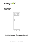
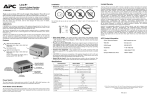
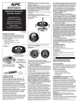
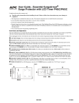
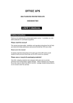
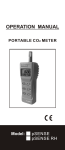
R
Surge Arrest PM Series
®
Model PMH3XLM
(For 380/220 Volt Power Systems)
Non-Modular Surge Protection Device (SPD)
User’s Manual
This User Manual is intended for use by qualified personnel only. The Surge Protection Device
defined in this manual contains no user-serviceable parts.
Installation and maintenance of the Surge Protection Device is to be accomplished by qualified/
licensed electrical personnel only, using the Service Manual for guidance.
Installation and maintenance of the Surge Protection Device by non-qualified/licensed electrical
personnel will void the warranty.
American Power Conversion denies warranty coverage, as well as any liability for a device that has
been installed or maintained by non-qualified/licensed personnel.
Copyright © 2001 American Power Conversion Corporation
132 Fairgrounds Road
P.O. Box 278
West Kingston, Rhode Island 02892 USA
990-0538 6/01
SurgeArrest PM Series
®
Contents
INTRODUCTION.......................................................................................................................................... 1
WARNINGS, CAUTIONS, and NOTES ..................................................................................................... 1
INSTALLATION and MAINTENANCE CONSIDERATIONS .............................................................. 1
Fastener Installation ........................................................................................................................... 1
Electrical Bonding and Grounding..................................................................................................... 1
Wire Routing ...................................................................................................................................... 1
Electrical Connector Mating .............................................................................................................. 1
Electro-Static Discharge..................................................................................................................... 2
Soldering ............................................................................................................................................ 2
INSTALLATION ........................................................................................................................................... 2
TESTING ........................................................................................................................................................ 2
UNPACKING and PRELIMINARY INSPECTION.................................................................................. 2
Storage................................................................................................................................................ 2
LOCATION CONSIDERATIONS .............................................................................................................. 2
Environment ....................................................................................................................................... 2
Audible Noise..................................................................................................................................... 2
Mounting and Cabinet Data ............................................................................................................... 2
Service Clearance............................................................................................................................... 3
Equipment Performance..................................................................................................................... 3
Product Orientation ............................................................................................................................ 4
System Grounding.............................................................................................................................. 4
ELECTRICAL CONNECTIONS ................................................................................................................ 4
Overcurrent Protection ....................................................................................................................... 4
Voltage Rating.................................................................................................................................... 4
Terminals............................................................................................................................................ 4
Parallel Connection ............................................................................................................................ 5
Wire Size ............................................................................................................................................ 5
PMH3XLM SERIES INSTALLATION INSTRUCTIONS....................................................................... 6
Typical Unit Installation, Three Phase WYE, 4 Wire, plus Ground.................................................. 6
Circuit Breaker and Disconnect Switch ............................................................................................. 8
OPERATION and FEATURES.................................................................................................................... 8
Status Panel Controls, Indicators, and Alarms................................................................................... 9
Audible Alarm and Control................................................................................................................ 9
Dry Contacts..................................................................................................................................... 10
Environmental Monitoring Unit Option........................................................................................... 10
CORRECTIVE MAINTENANCE (Repair) ............................................................................................. 11
Troubleshooting ............................................................................................................................... 11
Display Board Removal and Replacement Instructions................................................................... 12
PREVENTIVE MAINTENANCE - Inspection and Cleaning ................................................................. 12
REPLACEMENT PARTS .......................................................................................................................... 12
LIMITED WARRANTY ............................................................................................................................. 14
TECHNICAL SUPPORT............................................................................................................................ 14
i
Contents - continued
Tables
Table 1 - Voltage Rating and Service Type (by Model) .................................................................... 4
Table 2 - Relay Contact Pin Arrangement ....................................................................................... 10
Figures
Figure 1 - SPD Mounting Requirements............................................................................................ 3
Figure 2 - Typical Parallel Connections............................................................................................. 5
Figure 3 - Status Panel with Surge Counter Option ........................................................................... 9
Figure 4 - Troubleshooting Flow Chart............................................................................................ 11
Figure 5 - Display Board Locator Diagram ..................................................................................... 13
ii
INTRODUCTION
Thank you for choosing the APC SurgeArrest PMH3XLM Series Surge Protection Device (SPD).
This User Manual provides important information for the owner of APCs Non-Modular PMH3XLM SurgeArrest
SPD. Specific technical information contained in this manual has been provided for planning purposes only. Note:
SPDs are also known as Transient Voltage Surge Suppressors (TVSS). The SPD must be installed by qualified/
licensed electrical personnel only, using the Service Manual provided with the device. The installer should follow the
steps outlined in the Service Manual to insure proper installation. A copy of the installer’s invoice detailing the
installation of this device is required in order to obtain warranty service for the device. The only serviceable
component of this device is the Display Board Assembly. This device contains no user-serviceable parts.
Please read and understand all information contained in this manual prior to use. This manual is to be used as a guide
for using the device.
The APC modular Surge Protection Device (SPD) is a high quality, high energy surge attenuation system that has
been designed to protect sensitive equipment from damaging transient voltage surges in 380/220 volt power system
applications. The PMH3XLM unit is a parallel SPD designed for service entrance and downstream panelboard
applications. Proper use is imperative to maximize the surge suppressor’s effectiveness and performance.
The PMH3XLM provides surge protection per phase and is available with a 120kA per phase rating. All APC
products are extensively tested according to industry standards as set by IEC 60950, and is qualified for all circuit
capacities. Note: When planning the placement of this device, consideration should be given to the connection method
to be used. In some applications, this device may require several feet of wire. Increased wire lead length adversely
affects clamping voltages.
WARNINGS, CAUTIONS and NOTES
• Warnings statements in this manual provide information, which if not complied with, may result in
personnel injury or death.
• Cautions statements in this manual provide information, which if not complied with, may result in
damage to equipment.
• Notes presented in this manual contain information deemed essential to highlight.
INSTALLATION CONSIDERATIONS
For system deployment planning purposes, during installation into an electrical system, the SPD must NOT be
energized until the electrical system is completely installed, inspected, and tested. All conductors must be connected
and functional, including the neutral (blue wire). The voltage rating of the device and system must always be verified
before energizing the SPD.
Failure to follow these guidelines can lead to abnormally high voltage being applied to the SPD. This may cause the
SPD to prematurely fail or significantly shorten the effective life. The warranty does not cover an incorrectly installed
device.
TESTING
Also for system deployment planning purposes, any factory or on-site testing that exceeds the normal operating
voltage such as high-potential insulation testing, or any other tests where the suppression components will be
subjected to voltages higher than their rated "turn on" voltage, must be run with the SPD disconnected from the
power source. For 4-wire SPDs, the neutral connection at the SPD must also be disconnected prior to performing
high-potential testing, and then reconnected upon completion of the test.
Caution: The SPD and its associated suppression components must be disconneted during elevated
voltage testing. Failure to comply may result in damage to the suppression components
and/or other electronic components.
UNPACKING and PRELIMINARY INSPECTION
• Inspect the entire shipping container for damage or signs of mishandling before unpacking the unit.
• Remove the cardboard packing and further inspect the unit for any obvious shipping damages.
• If damage found is a result of shipping or handling, immediately file a claim with the shipping company and
forward a copy to APC.
Page 1
Storage
The unit should be stored in a clean, dry environment. Storage temperature is -40o C (-40o F) to +60o C (+140o F).
Avoid exposing the unit to areas of high condensation. All of the packaging materials should be left intact until the
unit is ready for installation. If the unit has been stored for an extended period of time, it may be necessary to clean
the unit and make a complete inspection of the unit prior to having it installed and placing it into service.
LOCATION CONSIDERATIONS
Environment
The SPD is designed to operate indoors in an ambient temperature range of -40o C (-40o F) to +60o C (+140o F) with
a relative humidity of 0% to 95% non-condensing. The standard unit is in a Type 1 industrial use enclosure intended
for indoor use. Primarily, it provides a degree of protection against contact with the enclosed equipment. It should not
be installed in areas with excessive dust, flammable materials, corrosive vapors or explosive atmospheres.
Audible Noise
The unit background noise is negligible, and does not restrict the location of the installation.
Mounting and Cabinet Data
For planning purposes, the PMH3XLM is designed to be wall mounted. The unit size is as shown in Figure 1, and
weighs 17 pounds (7.71 kg). Shipping weight is 19 pounds (8.618 kg).
6.0"
(15.24 cm)
5.5"D
(13.97 cm)
* Mounting Holes
are 5/16" (7.11 mm)
* Unit Weight is
17 lbs. (7.71 kg)
8.0"
(20.32 cm)
Display
Board
8.75"
9.5"
(22.22 cm) (24.13 cm)
8.0"
(20.32 cm)
Figure 1. SPD Mounting Requirements
**Surge Protection Devices are designed for use on the load side
of the service entrance disconnect only**
Service Clearance
In addition to national and local code requirements, 36 inches of service clearance is needed at the front of the SPD.
Page 2
WARNING
•
INSTALLATION or MAINTENANCE OF THIS SURGE PROTECTION DEVICE MUST BE
PERFORMED BY QUALIFIED PERSONNEL ONLY.
•
DURING NORMAL OPERATION, HAZARDOUS VOLTAGES ARE PRESENT INSIDE THE UNIT.
•
WHEN SERVICING THIS UNIT, SERVICE PERSONNEL MUST BE SURE TO FOLLOW ALL
ELECTRICAL SAFETY PRECAUTIONS.
•
ALL POWER SOURCES TO THIS UNIT SHOULD BE LOCKED OFF BEFORE SERVICING.
THIS WILL PREVENT THE RISK OF RECEIVING AN ELECTRICAL SHOCK.
Equipment Performance
For planning purposes, in order to obtain maximum system performance, the SPD must be located as close to the
circuit to be protected as possible, minimizing the interconnecting wire length. For every foot of wire length,
approximately one (1) nanosecond of turn-on/turn-off time is added, and approximately 175 volts (6kV/3kA, 8/20
microseconds) is added to the clamp voltage.
For optimum transient surge protection, staged surge suppression should be implemented at the service entrance and
all other electrical connections to the building (telephone, CATV, etc.). It should also be implemented at recognized
surge generating loads within the building (arc welding rigs, large motors, switched capacitors, etc.). Additionally, it
should be implemented for sensitive electronic loads (computer equipment, facsimile machines, copy machines, solid
state motor drives, variable frequency drives, etc.). For interconnected electronic loads (via data cabling), surge
protection devices should also be utilized to protect the devices on either end of the interconnecting data cables.
APC manufactures a complete line of surge protection devices for both alternating current (AC) and direct current
(DC) applications. Contact an authorized APC reseller, or order directly from APC at www.apc.com.
Product Orientation
To decode the Model Number and determine the unit’s configuration, locate the printed nameplate on the outside of
the unit. Note: The Serial Number, Date of Manufacture, and Suppression Voltage Rating (SVR) are also on the unit
identification nameplate. The Model Number can be decoded as follows:
•
•
•
•
PM identifies a SurgeArrest Panel Mount product. The following letter indicates the voltage and wiring
configuration of the device.
Following this letter is the number 3. This number identifies the surge current ratings to be 120kA per phase.
Following the number 3 is the letter X. This indicates that the unit is non-modular.
Following the "X" letter designation are the letters LM, which indicates that this model has been designed
for use in South America.
Options are detailed later in this manual.
System Grounding
For planning purposes, equipment grounding conductor must be used on all electrical circuits connected to the SPD.
This requirement is primarily for safety, although SPD performance is enhanced by proper grounding. Proper
operation of any surge suppression system or device depends on a proper grounding system. Incorrect grounding
practices will reduce the effectiveness or interfere with SPD system operation and performance, as well as endanger
personnel and equipment. For the best performance, use a single point ground system where the service entrance
grounding electrode system is connected to and bonded to all other available electrodes, building steel, metal water
pipes, driven rods, etc. For sensitive electronics and computer systems, the recommended ground impedance
measurement is 25 ohms or less. When a metallic raceway is used as an additional grounding conductor, an insulated
grounding conductor should be run inside the raceway. Adequate electrical continuity must be maintained at all
raceway connections. Do not use isolating bushings to interrupt a metallic raceway run. A separate isolated ground
for the SPD is NOT recommended.
Page 3
**On 4-Wire Power Systems, neutral to ground bonding should be
installed per national and local electrical codes.
Failure to comply may result in damage to the equipment.**
ELECTRICAL CONNECTIONS
Overcurrent Protection
The Surge Protection Device (SPD) draws very little current under normal conditions and will only conduct for a
brief duration upon encountering a transient surge voltage. APC SPDs contain internal fusing to protect against
abnormal voltage conditions. Note: Fuses are not replaceable.
Voltage Rating
Prior to having the SPD installed, verify that the unit has the correct voltage rating by checking the nameplate voltage
or model number. The service type should match the intended power source. See Table 1 for the voltage rating and
service type of the SPD.
Table 1: Voltage Rating and Service Type
Model Number
PMH3XLM
Voltage Rating and Service Type
220/380 Volts, 3- Phase, WYE
Terminals
Terminals have been provided inside the APC non-modular SPD for line (phase), neutral, and equipment safety
ground connections. Terminal wire size range for all models is #8 AWG. Installation torque is 65 inch-pounds.
!
WARNING
VERIFY THAT ALL POWER
CIRCUITS ARE DE-ENERGIZED
BEFORE MAKING CONNECTIONS
All electrical connections should be performed by a qualified/licensed electrician. All wiring
must comply with national and applicable local codes.
Parallel Connection
When making a parallel type of connection (Figure 2), the length of the wiring to the Surge Protection Device (SPD)
must be kept as short as possible to substantially enhance the performance. Long wire runs are to be avoided for the
unit to perform as intended.
To reduce the impedance the wire displays to surge currents, the phase, neutral, and ground conductors are to be
routed within the same conduit and should be tightly bundled or twisted together to optimize performance of the unit.
Sharp bends in the conductors are to be avoided.
Wire Size
With a parallel connection, the size of the wiring to the SPD is independent of the ampere rating of the circuit to be
protected. The recommended wire size is based on the unit’s transient surge current capabilities. #8 AWG is the
recommended wire size for phase, neutral, and ground.
**Surge Protection Devices are designed for use on the load side
of the service entrance disconnect only**
Page 4
To "Protected" Loads
Phase A
Phase B
Phases
Neutral
Phase C
Neutral Bus
Neutral
(if used)
Ground
Ground
Ground Bus
Interconnecting Wiring
* Minimize Length
* Avoid Sharp Bends
Figure 2. Typical Parallel Connections
WARNING
•
MAINTENANCE or INSTALLATION OF THIS SURGE PROTECTIVE DEVICE MUST BE
PERFORMED BY QUALIFIED PERSONNEL ONLY.
•
DURING NORMAL OPERATION, HAZARDOUS VOLTAGES ARE PRESENT INSIDE THE UNIT.
•
WHEN HAVING THIS UNITSERVICED, ENSURE SERVICE PERSONNEL FOLLOW ALL
ELECTRICAL SAFETY PRECAUTIONS (See Service Manual).
•
ALL POWER SOURCES TO THIS UNIT SHOULD BE LOCKED OFF BEFORE SERVICING.
THIS WILL PREVENT THE RISK OF RECEIVING AN ELECTRICAL SHOCK.
OPERATION and FEATURES
SPD's do not require operator intervention after installation. However, the LEDs should be checked weekly to ensure
that the SPD is functional.
NOTE: The PMH3XLM has a green LED for each phase which extinguish when the module is no longer providing
protection (fault condition). The only serviceable part is the Display Board Assembly (see Service Manual).
The PMH3XLM contains a diagnostic circuit which monitors the suppressors status continuously and automatically.
If a fault condition were to occur, the built-in front panel audible alarm will sound and a red "Service" LED will light,
indicating that the unit is in need of service by a qualified electrician.
Page 5
The audible alarm can be silenced by pressing the "Mute Alarm" button on the touchpad, until a qualified electrician
or service person is available to service the unit. The red "Service" LED will continue to be illuminated even though
the audible alarm has been silenced. This will continue until the fault condition has been cleared.
Have the electrician use the Service Manual to locate and repair the fault.
Status Panel Controls, Indicators, and Alarms
All indicators and controls are located on the front diagnostic panel (Figure 3) of the PMH3XLM unit. Each phase
features a tri-color LED indicator. Green indicates correct operation. Amber indicates reduced protection. Red
indicates loss of protection. If an inoperative condition were to occur, the built-in audible alarm will sound and the
red Service LED will illuminate. This indicates that the unit needs evaluation by a qualified electrician or technician.
Until a qualified person evaluates the unit, press the Mute Alarm touchpad to silence the alarm. (The LED indicator
above the Mute Alarm touchpad illuminates when the alarm is deactivated. Normal operation occurs with the Mute
Alarm LED extinguished.) The red Service LED will remain illuminated even though the Audible Alarm has been
silenced. The Test touchpad tests the red Service LED and the Audible Alarm.
If LEDs are illuminated in a manner that suggests contradictory information, there may be an internal logic problem
and the unit needs replacement. If none of the LEDs are illuminated, the unit may not be installed correctly. Please
note that the internal storage capacitor for surge counter backup must be energized for about 15 minutes before the
“count” push button will function. If a green LED is not illuminated and is suspect of being faulty, a qualified
electrician or technician may attempt to diagnose the problem by de-energizing the unit, removing the front cover and
exchanging ribbon cable leads with another phase (if available). Upon reenergizing the PMH3XLM, the appropriate
LED will illuminate if the suspect LED has failed. If troubleshooting indicates a failed LED, please contact APC
Technical Support at: 800-800-4APC.
SurgeArrest® PM
R
Test: Tests the red Service LED and audible alarm
Phase A
Phase B
Phase C
Service
Test
Reset
Reset: Resets the optional surge counter.
Mute Alarm: Turns the Alarm off. (Note that the
alarm is de-activated when the LED is lit).
Phase A, B, and C: Tri-color LED status indicators:
Green = Full protection
Amber = Partial protection
Red = No protection
Service: LED illuminates for any amber or red indication.
Mute
Alarm
Figure 3. Status Panel with Surge Counter Option
Audible Alarm and Control
The PMH3XLM device is equipped with an audile alarm which will sound in the event of an alarm condition. In
addition, the red Service LED will illuminate, indicating the device needs service. Press the Mute Alarm touchpad to
silence the alarm. The red Service LED will remain on even though the alarm is silenced. The Audible Alarm can be
tested by pressing the Test touchpad. This tests the alarm regardless of the Mute Alarm status. The Test touchpad
tests the red Service LED and the Audible Alarm.
Page 6
Dry Contacts
The PMH3XLM includes a set of Dry Contacts available at a terminal block at the right-front of the inside panel. This
feature provides two sets of normally open (NO) and normally closed (NC) contacts which can be used for remote
monitoring of the PMH3XLM’s operating status by changing state when there is an alarm condition. Examples of
remote monitoring equipment include a computer interface board, emergency management system, or APC’s
Environmental Monitoring Unit Option (see Environmental Monitoring Unit Option). The relay contact pin
arrangement is outlined in Table 2. (Note: The jumpered connections of Pins 7, 8, & 9 do not represent a third set of
contacts).
For applications using Dry Contacts, please note the following information:
•
The Dry Contacts are designed for low voltage or control signals only. The maximum switching current is 1
amp. The maximum switching voltage is 24 volts, DC or AC.
•
Higher energy applications may require additional relay implementation outside the PMH3XLM. Damage to
the PMH3XLM unit’s relay caused by implementation with energy levels in excess of those discussed in this
manual will not be covered by warranty.
Note that the Dry Contacts will allow the PMH3XLM unit to communicate with one (1) external device.
Table 2: Relay Contact Pin Arrangement
Relay Contact
Set 1
Form "C"
Relay Contact
Set 2
Form "C"
Pin
Contact Type
1
Normally Closed (1)
2
Common (1)
3
Normally Open (1)
4,7
Normally Closed (2)
5,8
Common (2)
6,9
Normally Open (2)
NOTE: Pin pairs 4 & 7, 5 & 8, and 6 & 9, are connected via jumper
internally. The combined current of each pin pair may not exceed 1 Ampere.
Environmental Monitoring Unit Option
APC offers a Environmental Monitoring Unit Option, which allows the user to monitor the alarm status of the
connected SPD. The product is available as a 120-volt external power supply (AP9312PM) or as a 100-240 volt
universal input external power supply (AP9312PMI).
The AP9312PM is connected to the SPD using Dry Contacts. When an alarm is triggered, the Dry Contact closes and
the Environmental Monitoring Unit Option sends up to four e-mail messages to preprogrammed addresses, notifying
the address that the SPD is in an alarm condition. The e-mail messages can be sent to computers, pagers, cell phones,
or Palm® Computers anywhere in the world over the internet.
The AP9312PM has its own internet protocol (IP) address and is usually connected to a 10Base/T communications
network. It then uses its internal browser software to host a web page on the internet. Facility managers can monitor
the status of the Environmental Monitoring Unit using their computer and internet browser, such as Microsoft®
Internet Explorer®. An qualified/licensed electrician is required for installation of the Environmental Monitoring
Unit Option to the Dry Contacts of the SPD.
Page 7
CORRECTIVE MAINTENANCE (Repair)
SurgeArrest PMH3XLM units are designed for years of reliable, trouble-free operation. However, even the most
reliable equipment can fail.
Built-in diagnostics are an integral part of the PMH3XLM and indicate if service is required. Audible alarms and
abnormal illumination of LEDs indicate problems within the PMH3XLM, and possibly within the electrical system.
Quality SPDs, such as the PMH3XLM, are designed and tested to withstand severe duty. However, various electrical
distribution problems exist that a PMH3XLM will not protect against. Should a problem arise, a qualified electrician
should first perform an overview of the electrical distribution system, including verification of proper voltages and
phasing. Regardless of the cause, PMH3XLMs will sacrifice themselves while attempting to protect their load.
Accordingly, a failed PMH3XLM may indicate other problems, as its failure is the effect rather than the cause.
Standard troubleshooting procedures should be used to isolate problems. See Figure 4 (Troubleshooting Flowchart)
for assistance. Replace bad components with identically rated parts to continue proper operation and safety. Note:
The only replaceable component of the PMH3XLM is the Display Board, or the unit itself.
Troubleshooting
Troubleshooting of an SPD consists of performing the sequence of steps provided in the Troublshooting Flow Chart
in Figure 4. Perform the steps in this chart only to the extent necessary to clear the fault.
Alarm
Audible/Visual
Red Service
LED Lit?
START
No
Yes
Possible
Display
Board
Failure.
Call APC
Technical
Support
1-800-800-4APC
END
Yes
All
Front Panel
Green LEDs
Lit?
All
Front Panel
Green LEDs
Lit?
Yes
No
Apparent
Problem
No
No
Have
Electrician
Verify Voltage is
Correct on all
Phases?
No
Have Electrician
Correct
Power Utility
Feed and
Verify
Power Levels
and
Operation
Yes
WARNING
SECURE ALL
POWER
(REMOVE POWER)
TO THE SPD
END
Possible
Unit
Failure.
Call APC
Technical
Support
1-800-800-4APC
Figure 4. Troubleshooting Flow Chart
Page 8
END
PREVENTIVE MAINTENANCE - Inspection and Cleaning
Inspection of the SPD should be performed periodically to maintain reliable system performance and continued
transient voltage surge protection. While it is difficult to establish a preventive maintenance schedule because
conditions vary from location to location, inspections for failed LEDs and other signs of trouble utilizing the built-in
diagnostics should be performed on a routine basis (weekly or monthly).
REPLACEMENT PARTS
The only replaceable item in the SPD is the Display Board Assembly (see Figure 5), and must be replaced by a
qualified electrician.
Ribbon Cable
Connectors
Ribbon Cables
(to Chassis)
Display Board
Retaining Hardware
(4 places)
Display Board
Chassis Cover
(Chassis not shown)
Ground Wire
(to Chassis)
Not to exact scale.
Figure 5. Display Board Locator Diagram
Page 9
LIMITED WARRANTY
APC warrants it’s AC panel protection products against defects in workmanship and materials for 5 years from the
date of original purchase. The panel protection device must be installed by a qualified and licensed electrician in
order to qualify for warranty protection.
Liability is limited to the replacement of the defective product. A Return Material Authorization must be given by
APC prior to the return of any product (see Technical Support and Customer Service). A copy of the invoice from the
installer (electrician or electrical service company) must accompany the defective device being returned. If the return
of a device is authorized by APC, APC will immediately ship a replacement unit to the customer. Along with the
replacement unit, APC will include a pre-paid shipping tag for the return of the originally defective unit. The
replacement unit will not be warranteed unless the defective unit is received by APC.
Under no circumstance is APC responsible for the cost of removal or installation of any panel protection device.
APC also offers unlimited replacement of modular and component parts within the warranty period previously
described.
APC specifically disclaims all other warranties, expressed or implied. Additionally, APC will not be responsible for
incidental or consequential damages resulting from any defect in any product or component thereof.
TECHNICAL SUPPORT and CUSTOMER SERVICE
United States and Canada:
1-800-800-4APC
This manual, as well as information about the entire APC product line is available on the internet at: www.apc.com.
Prior to calling APC for technical assistance or ordering parts, please have the following information available:
Model Number of unit:
________________________________________________________
Serial Number of unit:
________________________________________________________
Manufacture Date:
________________________________________________________
Purchase Date:
________________________________________________________
Your Order Number:
________________________________________________________
Return Shipment Address
American Power Conversion Corporation
1600 Division Road
Dock 25
West Warwick, Rhode Island 02893 USA
Attn: RMA#_______________________
Page 10