1
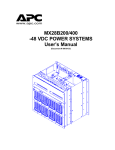
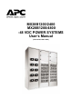
MX28B1200/2400
MX28B1200/4800
-48 VDC POWER SYSTEMS
User’s Manual
(Document # 990-1148A)
Table of Contents
1
SAFETY FIRST! .....................................................................................................................1
1.1.
1.2.
2
INTRODUCTION ....................................................................................................................2
2.1.
2.2.
3
WARNING SYMBOLS .........................................................................................................1
GENERAL PRECAUTIONS: ..................................................................................................1
GENERAL INFORMATION ....................................................................................................2
HOW TO USE THIS MANUAL ..............................................................................................2
INSTALLATION .....................................................................................................................5
3.1.
UNPACKING EQUIPMENT ...................................................................................................5
3.2.
MECHANICAL INSTALLATION ..............................................................................................5
Room / Location......................................................................................................................5
Mounting .................................................................................................................................6
Power Bus Connections .........................................................................................................6
Circuit Breaker/LVD Ribbon Cable Connections.....................................................................8
Fuse Alarm Ribbon Cable Connections..................................................................................9
Ventilation ...............................................................................................................................9
3.3.
AC POWER CONNECTIONS ...............................................................................................9
3.4.
BATTERY CONNECTIONS .................................................................................................11
Planning the Battery Installation ...........................................................................................11
Connecting the Battery Cables .............................................................................................12
3.5.
DC SYSTEM GROUNDING ...............................................................................................13
3.6.
DC POWER OUTPUT OVER-CURRENT PROTECTION..........................................................14
DC Plug-in Circuit Breakers ..................................................................................................14
DC Bolt-in Circuit Breakers ...................................................................................................17
Telecom Fuses .....................................................................................................................18
3.7.
INSTALLATION OF CIRCUIT BREAKERS AND FUSES .............................................................19
Plug-in Circuit Breaker Installation........................................................................................19
Bolt-in Circuit Breaker Installation.........................................................................................20
Telecom Fuse Installation.....................................................................................................21
GMT Fuse Installation...........................................................................................................21
3.8.
LOAD CONNECTIONS ......................................................................................................22
Cable Size Considerations ...................................................................................................22
Circuit Breaker Connections (1 to 50 Amps).........................................................................22
Circuit Breaker Connections (60-100 Amps) ........................................................................22
Return Connections (1-100 Amps) .......................................................................................22
GMT Fuse Connections........................................................................................................23
3.9.
MONITORING AND RELAY OUTPUT CONNECTIONS .............................................................23
Front Panel DB9 Connection ................................................................................................23
“Smart” Cable DB9 Connection ............................................................................................23
RJ45 Ethernet Connector .....................................................................................................24
Relay Output Connections ....................................................................................................24
MX28B1200/2400 MX28B1200/4800 –48 VDC User’s Manual
Page ii
3.10.
3.11.
4
EXTERNAL ALARM INPUT CONNECTIONS ..........................................................................25
RECTIFIER MODULE INSTALLATION...................................................................................26
COMMISSIONING AND PREVENTIVE MAINTENANCE ....................................................27
4.1.
PRE-COMMISSIONING INSPECTION ...................................................................................27
Environment..........................................................................................................................27
Electrical Installation .............................................................................................................27
Battery Visual and Safety Inspection ....................................................................................27
4.2.
COMMISSIONING.............................................................................................................28
Initial Set-up..........................................................................................................................28
AC Power Up ........................................................................................................................28
DC Power Up:.......................................................................................................................29
Rectifier Test:........................................................................................................................29
LVD Test...............................................................................................................................29
Battery Power Up..................................................................................................................29
Circuit Breaker/ Fuse Test: ...................................................................................................30
User Inputs ...........................................................................................................................30
Output Relays: ......................................................................................................................30
Battery Temperature Compensation.....................................................................................30
4.3.
FINAL INSPECTION: .........................................................................................................31
5
OPERATION ........................................................................................................................32
5.1.
TECHNICAL DESCRIPTION................................................................................................32
5.2.
RECTIFIER MANAGEMENT................................................................................................32
AC Input Power.....................................................................................................................32
DC Output Power..................................................................................................................32
Rectifier alarms reporting......................................................................................................32
5.3.
SYSTEM MANAGEMENT ...................................................................................................33
System Output Capacity .......................................................................................................33
System Voltage Control ........................................................................................................33
System Current.....................................................................................................................33
System Status and Alarm Reporting.....................................................................................34
5.4.
DC DISTRIBUTION ..........................................................................................................34
5.5.
BATTERY MANAGEMENT .................................................................................................34
Battery Charging and Protection...........................................................................................34
Battery/Load Low Voltage Disconnect ..................................................................................35
5.6.
CONTROLS AND INDICATORS ...........................................................................................35
Front Panel User Interface....................................................................................................35
Parameter Locations, Descriptions, and Default Values.......................................................36
Control Unit Menu Structure .................................................................................................46
Front Panel LED Indicators...................................................................................................52
5.7.
ALARM OUTPUTS (OUTPUT RELAYS)................................................................................52
5.8.
EXTERNAL ALARM INPUTS (INPUT RELAYS) ......................................................................53
6
REMOTE MONITORING ......................................................................................................54
6.1.
6.2.
DESCRIPTION .................................................................................................................54
PHYSICAL CONNECTIONS ................................................................................................54
MX28B1200/2400 MX28B1200/4800 –48 VDC User’s Manual
Page iii
6.3.
7
COMMAND AND MONITORING PROTOCOL .........................................................................54
PREVENTIVE MAINTENANCE............................................................................................55
7.1.
EQUIPMENT ...................................................................................................................55
7.2.
INSPECTION ...................................................................................................................55
Environmental Inspection .....................................................................................................55
System Visual and Safety Inspection....................................................................................55
Battery Visual and Safety Inspection ....................................................................................56
7.3.
TEST .............................................................................................................................56
System Voltage Test.............................................................................................................56
Rectifier Current Test............................................................................................................56
Rectifier Current Share Test .................................................................................................57
System Current Test.............................................................................................................57
Rectifier Alarm Test ..............................................................................................................57
System Temperature Test ....................................................................................................57
Battery Current Test .............................................................................................................57
Battery Temperature Test .....................................................................................................58
LVD Test...............................................................................................................................58
Battery Preventive Maintenance Procedure .........................................................................58
7.4.
FINAL INSPECTION: .........................................................................................................59
8
SPECIFICATIONS................................................................................................................60
8.1.
AC INPUT ......................................................................................................................60
1MRF28H54BV Rectifiers.....................................................................................................60
1MRF28H54BV50 Rectifiers.................................................................................................60
8.2.
DC OUTPUT (WITH EITHER 1MRF28H54BV RECTIFIERS AND 1MRF28H54BV50
RECTIFIERS) ..............................................................................................................................61
8.3.
CONTROLS AND INDICATORS ...........................................................................................61
Rectifiers...............................................................................................................................61
Power Shelf Control Unit ......................................................................................................62
8.4.
MECHANICAL .................................................................................................................63
8.5.
ENVIRONMENTAL ............................................................................................................63
8.6.
COMPLIANCE .................................................................................................................63
9
10
APC WORLDWIDE CUSTOMER SUPPORT.......................................................................64
LIMITED PRODUCT WARRANTY....................................................................................65
MX28B1200/2400 MX28B1200/4800 –48 VDC User’s Manual
Page iv
Revision History
Revision
1
Date
31 JAN, 2002
By
JNF
Description
Converted to APC numbering
2
28 SEP, 2003
BET
Updated Format and added 4800
Table of Figures
FIGURE 2.2-1 MX28B-1200 –48 VDC POWER PLANT RECTIFIER BAY.............................................3
FIGURE 2.2-2 MX28B BLOCK DIAGRAM ...............................................................................................4
FIGURE 3.2-1 FLOOR MOUNTING DIMENSIONS .................................................................................6
FIGURE 3.2-2 MX28B-1200-2400 HAS A MAXIMUM CAPACITY OF 2400 AMPS.............................7
FIGURE 3.2-3 THE MX28B1200-4800 CAN BE EXPANDED TO 4800 AMPS. .....................................7
FIGURE 3.2-4 SPLICE PLATE INSTALLATION ......................................................................................7
FIGURE 3.2-5 CIRCUIT BREAKER / LVD EXPANSION BOARD .........................................................8
FIGURE 3.2-6 WAGO FUSE ALARM BREAKOUT BOARD ..................................................................9
FIGURE 3.3-1 AC INPUT WIRING...........................................................................................................10
FIGURE 3.4-1 BATTERY CABLE CONNECTION LOCATIONS..........................................................12
FIGURE 3.4-2 BATTERY PROBE CONNECTION..................................................................................13
FIGURE 3.4-3 BATTERY PROBE INSTALLATION ..............................................................................13
FIGURE 3.5-1 DC SYSTEM GROUNDING .............................................................................................14
FIGURE 3.5-2 BOX FRAME GROUND....................................................................................................14
FIGURE 3.6-1 DC DISTRIBUTION (FRONT COVER OPENED) ..........................................................15
FIGURE 3.6-2 PLUG-IN CIRCUIT BREAKERS ......................................................................................16
FIGURE 3.6-3 PLUG-IN CIRCUIT BREAKER KITS ..............................................................................16
FIGURE 3.6-4 BOLT-IN CIRCUIT BREAKERS ......................................................................................17
FIGURE 3.6-5 TELECOM FUSES .............................................................................................................18
FIGURE 3.7-1. INSTALLATION OF CIRCUIT BREAKERS..................................................................19
FIGURE 3.7-2 CIRCUIT BREAKER ALARM WIRING ..........................................................................20
FIGURE 3.7-3 GMT FUSE TEMPERATURE DE-RATING CHART......................................................21
FIGURE 3.8-1 LOAD CONNECTIONS FOR SNAP-IN BREAKERS .....................................................23
FIGURE 3.8-2 RETURN CONNECTIONS................................................................................................23
FIGURE 3.9-1 INTERFACE BOARD ........................................................................................................24
FIGURE 3.9-2 OUTPUT RELAY CONNECTIONS..................................................................................25
FIGURE 3.10-1 EXTERNAL ALARM INPUT DEFINITION ..................................................................25
FIGURE 3.10-2 EXTERNAL ALARM INPUT CONNECTIONS ............................................................25
FIGURE 5.6-1 MENU TOP LINE ..............................................................................................................36
MX28B1200/2400 MX28B1200/4800 –48 VDC User’s Manual
Page v
1
Safety First!
It is very important to follow all safety procedures when unpacking, installing and operating any
sort of power equipment.
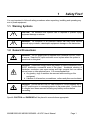
1.1. Warning Symbols
CAUTION: An indication that special care is required to prevent injury,
equipment damage or misuse
WARNING: An indication of an electrical hazard that may cause serious
personal injury or death, catastrophic equipment damage or site destruction.
1.2. General Precautions:
WARNING: The DC power plant is supplied from a nominal 220VAC, 50/60
Hz source. Keep the AC input enclosure cover in place when the system is
operational or energized
WARNING: Hazardous energy levels are present on bare conductors in the 48VDC distribution connection area of the plant. Accidental shorting of
distribution conductors can cause arcing and high currents that can cause
serious burns or other physical harm. It is recommended that:
a. Any jewelry, rings or watches be removed while working on this
equipment.
b. Handles of all wrenches, screwdrivers, cutters and pliers are insulated.
WARNING: Ensure that all of the DC and external AC circuit breakers are in
the OFF position prior to connecting service to the power plant. Confirm that
all voltages have been removed including any battery sources before
proceeding.
Specific CAUTION and WARNING will be placed in manual where appropriate.
MX28B1200/2400 MX28B1200/4800 –48 VDC User’s Manual
Page 1
2
Introduction
2.1. General Information
DC Power Plants from APC have unique features that make them easy to install, maintain, and
upgrade. The rectifier units are modular and truly “hot-pluggable” into the shelf assembly
without any separate AC wiring. All system settings are made from the system control unit that
provides monitoring and control functions for each component of the system as well as alarm
listings for system diagnosis and maintenance.
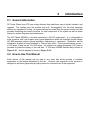
The APC Model MX28B is a modular stand-alone -48V DC power plant. It is configurable in
such a manner that it will support most typical applications within the specified current ranges
(50-4800 amperes) without special application engineering or assistance. Distribution can be
included for a variety of circuit breakers or Telecom style fuses. These circuit breakers can be 1
to 700 amps. Fuses can be 70 to 600 amps. An optional low voltage disconnect (LVD) can be
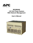
provided on either the battery or the load side. A 1200 amp MX28B Rectifier Bay is shown in
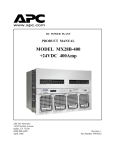
Figure 2.2-1. A block diagram is shown in Figure 2.2-2.
2.2. How to Use This Manual
Each section of this manual can be read in any order and should provide a complete
explanation of the subject described by the title. However, the sequence of the sections is
designed to provide a typical step-by-step process for successful use of the equipment.
Figure 2.2-1 MX28B-1200 –48 VDC Power Plant Rectifier Bay
MX28B1200/2400 MX28B1200/4800 –48 VDC User’s Manual
Page 3
Figure 2.2-2 MX28B Block Diagram
MX28B1200/2400 MX28B1200/4800 –48 VDC User’s Manual
Page 4
3
Installation
3.1. Unpacking Equipment
Remove equipment from packing material and inspect for shipping damage or missing items. It
is important to report damage or material shortages to the shipping carrier while a
representative is on site.
If concealed damage or material shortages are found at a later time, contact the shipper to
make arrangements for inspection and claim filing. Refer to Section 7 in the event it is
necessary to return equipment to APC.
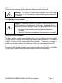
CAUTION: Appropriate lifting techniques and safety equipment should be
used to remove equipment from packing.
PLEASE RECYCLE: The shipping materials can be recycled. Please save
them for later use or dispose accordingly.
3.2. Mechanical Installation
Room / Location
NOTE: The APC Model MX28B DC power plant is to be installed in a room, vault, or similar
enclosure that is accessible only to qualified persons in accordance with the NEC or the
authority having jurisdiction.
Prior to installation, drawings, floor loading requirements, external alarm points, AC service
entrance, and grounding schemes should all be checked and confirmed. If batteries are to be
mounted in a room separate from the power plant, careful attention should be paid to battery
cable voltage drop effects. Environmental operating temperatures and ventilation/cooling
considerations should also be noted, not just for the power system but also for all other
equipment that may reside in the power room area.
MX28B1200/2400 MX28B1200/4800 –48 VDC User’s Manual
Page 5
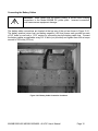
Mounting
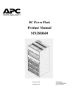
The box frame housing the MX28B components is self-supporting, but designed to be bolted to
the floor of the housing structure. Figure 3.2-1 shows the footprint of the box frame and the
mounting points with dimensions (shown in inches). Consult the system design specifications to
see if it is necessary to electrically isolate the frame from the floor structure. This is required in
many installations.
Figure 3.2-1 Floor Mounting Dimensions
Systems with multiple box frames are mounted with each frame touching, side by side. The
side cover panels where two frames touch are removed so that bus work and control cables can
pass between the frames. Three holes are provided in center vertical rail of each side to allow
the frames to be mechanically secured to each other if desired.
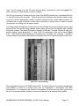
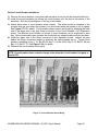
Power Bus Connections
At the top of each bay there are 3 power buses that transfer the power from 1 bay to another.
The system is rated such that the entire load can be run from a fuse or circuit breaker bay
mounted next to the rectifier bays. The MX28B-1200/2400 has a maximum of two rectifier bays.
The MX28B-1200/4800 can be expanded to four rectifier bays. The power buses are connected
together in each bay by splicing the buses together. The MX28B1200/2400 is a 1200 Amp
system expandable to 2400 Amps. The MX28B-1200/4800 is a 1200 Amp system expandable
to 4800 Amps. Each MX28B-1200/2400 power bus is comprised of 2 laminations of 5” X 1/4”
bus. See Figure 3.2-2 for details. Each MX28B-1200/4800 power bus is comprised of 3
laminations of 6” X 1/4” bus. See Figure 3.2-3 for details. The power bays are spliced together
with splice plates provided with each expansion bay. The size and thickness of the splice plates
must match the power bus. See Figure 3.2-4 for details.
MX28B1200/2400 MX28B1200/4800 –48 VDC User’s Manual
Page 6
Figure 3.2-2 MX28B-1200-2400 has a maximum
capacity of 2400 Amps.
Figure 3.2-3 The MX28B1200-4800 can be
expanded to 4800 Amps.
Figure 3.2-4 Splice Plate Installation
MX28B1200/2400 MX28B1200/4800 –48 VDC User’s Manual
Page 7
Circuit Breaker/LVD Ribbon Cable Connections
Additional cables must be connected between cabinets to ensure that the circuit breaker alarms
in the expansion bays are reported correctly. The circuit breakers and LVDs are connected
together through the use of a Circuit Breaker / LVD Expansion Board. The ribbon cables on the
left hand side of the board go to the bay to the left. The ribbon cables on the right hand side of
the board go to the bay to the right. If there is an open Alarm Contact Bus connector (no bay to
the side of the unit) the cable connector is left open and no further action is required. However if
the LVD Bus ribbon cable connector is open, the pins nearest the connector will have to be
jumpered. Install the jumpers using Figure 3.2-5 as a guide to jumper orientation. If a cable is
installed remove the jumpers on the pins nearest the installed ribbon cable.
Figure 3.2-5 Circuit Breaker / LVD Expansion Board
MX28B1200/2400 MX28B1200/4800 –48 VDC User’s Manual
Page 8
Fuse Alarm Ribbon Cable Connections
There is a 16-conductor ribbon cable, if any bay has fuses installed. This cable ties together the
Wago breakout board in each bay with fuses. The ribbon cable must connect all the Wago
breakout boards together with one ribbon cable. The idea is that each fuse will have one wire in
the ribbon cable for the alarm. Two fuse alarm wires should not be connected to the same fuse.
See Figure 3.2-6 for details. Ribbon cable pin 1 is for Fuse 1. Ribbon cable pin 2 is for Fuse 2
etc.
Figure 3.2-6 Wago Fuse Alarm Breakout Board
Ventilation
The rectifier modules for this system have fans that provide front-to-rear airflow for internal
cooling. The MX28B housing should mounted such that there is free airflow to the front and top
of the unit. [Refer to Section 8.5 for environmental characteristics.] Free airflow should be
ensured so that the power system can provide full power without de-rating.
3.3. AC Power Connections
WARNING: Ensure that all of the external DC and AC circuit breakers are in
the OFF position prior to connecting service to the power plant. Confirm that
all voltages have been removed including any battery sources before
proceeding.
The MX28B DC power plant requires the supply of 208/220/240/277 VAC single-phase, 50/60
Hz power through individual external 20-amp circuit breakers to the AC input terminal block
connections for each rectifier module in the system. Two rectifier modules are required to
accommodate the full AC input voltage range. The 1MRF28H54BV rectifier is designed for the
standard 208/220/240 VAC input service, while the 1MRF28H54BV50 is used for the 277 VAC
MX28B1200/2400 MX28B1200/4800 –48 VDC User’s Manual
Page 9
input. The AC wiring, from the AC input terminal block connections to the hot-pluggable AC
input connector for each rectifier, is factory installed.
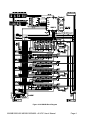
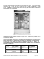
The AC input enclosure, located at the top rear of the MX28B rectifier bay, is provided with nine
¼ -inch pilot holes in the top plate. Remove the ac input enclosure from the box frame in order
to punch or drill the appropriate number of conduit openings for the conduit size(s) desired. Do
not leave the ac input enclosure in place when punching or drilling holes in order to prevent
metal pieces from falling into the power system.
AC wiring passing through the conduit will be routed through the access opening in the ac input
enclosure into the vertical wiring channel where safety ground bar and rectifier input terminal
blocks are located. The terminal block(s) is labeled as Rectifier 1 through Rectifier 4 with each
position having inputs designated “L1” and “L2/N” for connection of the two ac wires Figure
3.3-1. Each terminal block represents connections for one shelf, with positions 1 through 4
corresponding to the rectifier shelf positions numbered from left to right as viewed from the front.
Figure 3.3-1 AC Input Wiring
The suggested wire size is #10 AWG rated at 90°C or higher; however, the ambient temperature
and number of wires in a conduit must also be considered in accordance with NEC
requirements. It is suggested that feeds for four rectifiers (8 wires) and one safety ground wire
be run in a one-inch conduit; however, be sure to follow any local electrical wiring codes.
MX28B1200/2400 MX28B1200/4800 –48 VDC User’s Manual
Page 10
If the AC input power is provided from a three-phase distribution panel, the circuit breaker
positions should be selected such that the load is balanced as much as possible.
WARNING: The MX28B DC power plant is supplied from a high voltage
source. Keep the AC input enclosure in place when the system is operational
or energized.
3.4. Battery Connections
WARNING: Hazardous energy levels are present on bare conductors in the 48VDC distribution connection area of the plant. Accidental shorting of
distribution conductors can cause arcing and high currents that can cause
serious burns or other physical harm. It is recommended that:
c. Any jewelry, rings or watches be removed while working on this
equipment.
d. Handles of all wrenches, screwdrivers, cutters and pliers are insulated.
Planning the Battery Installation
The battery cable(s) should be sized sufficiently large to limit the voltage drop from the MX28B
DC power plant to the battery during charging per system design requirements. The cable(s)
must also carry the full load current during battery operation. If assistance is required to
determine the necessary cables for the application, contact your sales representative or APC.
An external fuse or circuit breaker (various options are available from APC) is recommended in
the negative line (located at the battery end) to protect the cables from the battery to the MX28B
DC power plant. The power plant can monitor auxiliary contacts from this breaker.
MX28B1200/2400 MX28B1200/4800 –48 VDC User’s Manual
Page 11
Connecting the Battery Cables
WARNING: Make certain that the battery polarity is correct when making
connections to the Model MX28B DC power plant. Incorrect connection
could cause severe equipment damage.
The battery cable connections are located at the top rear of the unit as shown in Figure 3.4-1.
The battery positive (return bus) and battery negative (-48V bus) buses each provide four sets
of 3/8” holes on one-inch or 1-3/4” centers for connecting two-hole battery cable lugs. Connect
the battery cables as applicable using 3/8-16 bolts (not provided) and tighten them with a torque
wrench to 200 in-lbs (23 N-m).
Figure 3.4-1 Battery Cable Connection Locations
MX28B1200/2400 MX28B1200/4800 –48 VDC User’s Manual
Page 12
Battery Temperature Probe Installation
The optional temperature probe is used to monitor the battery string temperature. To get the
most representative temperature measurement, the probe should be placed in contact with a
battery cell that is centrally located. The probe should be placed directly in contact with the cell
(not the frame surrounding the cell). Generally, the cell cover can be used; be careful not to
allow the probe body to touch the terminals. Remove the adhesive protection strip from the
probe body and press the adhesive side of the probe on the battery cell cover. See Figure 3.4-3
for details. Plug the connector end of the temperature probe into J5 of the control unit
backplane card. Route the cable as required positioning the probe on the selected battery cell.
See Figure 3.4-2 for Details.
Figure 3.4-2 Battery Probe Connection
Figure 3.4-3 Battery Probe Installation
3.5. DC System Grounding
The Positive Battery connection (return bus) for the power plant must be connected to the
Master Station Ground. The return bus provides 3/8” holes on 1 inch or 1-3/4 inch centers for
connection of a two-hole lugged cable to the Central Office Ground. Details for this connection
should be provided in the site electrical grounding plans.
A connection to tie the frames together is also available. At the top of both sides of the box
frame is a pair of studs for connecting a grounding cable. This #6 AWG cable is provided with
each expansion frame.
MX28B1200/2400 MX28B1200/4800 –48 VDC User’s Manual
Page 13
Figure 3.5-1 DC System Grounding
Figure 3.5-2 Box Frame Ground
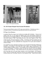
3.6. DC Power Output Over-Current Protection
There are several different options for DC output power distribution. Distribution provides a
convenient method of connecting the load cables as well as over-current protection.
DC Plug-in Circuit Breakers
A standard 48-position plug-in circuit breaker tier provides -48V distribution. Various circuit
breaker sizes from 1 to 100 amps are available, with 60-100 amp breakers requiring two
positions and a circuit breaker adapter kit. Each rectifier bay has two 24-position breaker tiers.
Each breaker tier is connected at its center to the -48V DC bus, and each side of the tier has a
total current capacity of 300A. Each breaker tier has a total current capacity of 600A. Each
rectifier bay has a total current capacity of 1200A. It is therefore necessary to balance the load
on the rectifier bay to avoid overloading any section of the output bus. Also when planning the
output installation, take into consideration the configuration of the plant and the number of
rectifiers installed.
Any combination of up to 48 single (1-50 Amp) or up to 24 double (60-100 Amp) breakers may
be installed. If all rectifier bays are installed with snap-in breakers, up to 192 single or 96 double
breakers may be installed. In the main bay a pair of ribbon cables routed directly to the
controller backplane handles alarming. In the expansion bays, each 24-breaker tier is alarmed
as a group of breakers. A two-pin connector on each tier connects to the Circuit Breaker
expansion board in each bay. Circuit breaker alarms can be monitored by attaching the other
end of the alarm wire to the gray Wago connector on the Circuit Breaker / LVD Expansion
board. Since the normally open contacts are monitored, any tripped breaker will give an alarm.
Install the alarm wire in the Wago connector on the expansion board. Jumper the pins behind
the Wago connectors based on what bay the circuit breaker tiers are in. Typical circuit breaker
numbering is bay 1: Cir Bkr 1-48, Bay 2: Cir Bkr 49-50, Bay 3: Cir Bkr 51-52 and Bay 4: Cir Bkr
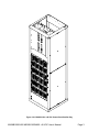
53-54. Figure 3.6-1 shows the power plant’s main bay (with ribbon cables) DC distribution
section with the front cover opened.
Figure 3.6-1 DC Distribution (Front Cover Opened)
Available plug-in circuit breakers are shown in Figure 3.6-2. These are only breakers and do
not include any hardware.
Plug-in circuit breakers rated at 60A or more require two mounting positions and require a circuit
breaker adapter, which is included in the circuit breaker kit. Adaptors are available with studs
for #10-32 nuts on 5/8” centers, #10-32 nuts on ¾” centers, or ¼-20 nuts on 1” centers. The
circuit breaker kit includes all necessary mounting hardware. Available plug-in circuit breakers
are shown in Figure 3.6-2.
BREAKER
RATING
1A
FFA-0014
BREAKER
RATING
40 A
FFA-0020
3A
FFA-0015
50 A
FFA-0025
5A
FFA-0016
60 A
530-9088
PART NUMBER
MX28B1200/2400 MX28B1200/4800 –48 VDC User’s Manual
PART NUMBER
Page 15
10 A
FFA-0017
70 A
530-9089
15 A
530-9093
80 A
530-9090
20 A
FFA-0018
100 A
530-9091
30 A
FFA-0019
Figure 3.6-2 Plug-in Circuit Breakers
BreakerRating
Part Number
Adaptor Size
60 A
FFA-0021-1
#10 studs on 5/8” centers
60 A
FFA-0021-2
#10 studs on ¾” centers
60 A
FFA-0021-3
¼” studs on 1” centers
70 A
FFA-0022-1
#10 studs on 5/8” centers
70 A
FFA-0022-2
#10 studs on ¾” centers
70 A
FFA-0022-3
¼” studs on 1” centers
80 A
FFA-0023-1
#10 studs on 5/8” centers
80 A
FFA-0023-2
#10 studs on ¾” centers
80 A
FFA-0023-3
¼” studs on 1” centers
100 A
FFA-0024-1
#10 studs on 5/8” centers
100 A
FFA-0024-2
#10 studs on ¾” centers
100 A
FFA-0024-3
¼” studs on 1” centers
Figure 3.6-3 Plug-in Circuit Breaker Kits
MX28B1200/2400 MX28B1200/4800 –48 VDC User’s Manual
Page 16
DC Bolt-in Circuit Breakers
Bolt in Breakers in a variety of sizes up to 700 Amps are available. Triple pole breakers are
available in sizes ranging from 400-700 Amps. Double pole breakers are available in sizes
ranging from 250-400 Amps. Single pole breakers are available in sizes ranging from 100-225
Amps. Small breakers (half the size of a single pole breaker) are available in sizes ranging from
1-100 Amps.
Two different panels are available for breaker mounting. AAB-0647 has cutout holes for 4 triple
pole breakers. Each hole will accept one triple pole breaker, 1 double and one single pole
breaker or 3 single pole breakers. AAB-0648 has cutout holes for 6 double pole breakers. Each
hole will accept one double pole breaker or 2 single pole breakers. Each double breaker hole
will accommodate 4 small breakers ranging in size from 1 to 100 Amps. See Figure 3.6-4 for
details.
Figure 3.6-4 Bolt-in Circuit Breakers
MX28B1200/2400 MX28B1200/4800 –48 VDC User’s Manual
Page 17
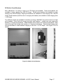
Telecom Fuses
Telecom fuses in sizes ranging from 70 – 600 Amps are available. A panel in each rectifier bay
will accommodate 4 fuse holders. Typical fuse numbering is Bay 1: Fuse 1-4, Bay 2: Fuse 5-8,
Bay 3: Fuse 9-12 and Bay 4: Fuse 13-16. Only one fuse can be hooked up to any alarm wire.
Refer to the following pictures for more information.
Figure 3.6-5 Telecom Fuses
MX28B1200/2400 MX28B1200/4800 –48 VDC User’s Manual
Page 18
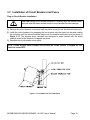
3.7. Installation of Circuit Breakers and Fuses
Plug-in Circuit Breaker Installation
CAUTION During circuit breaker installation, carefully align the breaker alarm
terminals with the alarm terminal board to avoid breaker terminal damage.
1) Remove the circuit breaker cover panel and the plastic cover(s) from the desired location(s).
2) Install the circuit breaker(s) by snapping the top terminal onto the upper bus bar and rotating
the unit down until the second terminal snaps onto the breaker termination post as shown in
Figure 3.7-1 The breaker alarm terminals are designed to make contact with the alarm
terminal board as the breaker is snapped into place.
3) Reattach the circuit breaker cover panel.
NOTE: Circuit breaker alarm contacts close when the circuit breaker is tripped but not
when it is turned OFF.
Figure 3.7-1. Installation of Circuit Breakers
MX28B1200/2400 MX28B1200/4800 –48 VDC User’s Manual
Page 19
Bolt-in Circuit Breaker Installation
1) Remove the circuit breaker cover panel and the plastic cover(s) from the desired location(s).
2) Install the circuit breaker(s) by bolting the circuit breaker onto the bus at the bottom of the
assembly. Bolt the lug landing bus to the top of the breaker.
3) Attach alarm wires to circuit breaker alarm outputs. The wires should be attached to the
contacts that are open when the breaker is on and closed when the breaker is off or tripped.
See Figure 3.7-2 for details. Circuit breaker alarms can be monitored by attaching the other
end of the alarm wire to the gray Wago connector on the Circuit Breaker / LVD Expansion
board. Six different circuit breaker or groups of circuit breakers can be monitored in each
bay. Since the normally open contacts are monitored, any tripped breaker will give an alarm.
4) Install the alarm wire in the Wago connector on the expansion board. Jumper the pins
behind the Wago connectors based on what bay the circuit breaker are in. Typical circuit
breaker numbering is bay 1: Cir Bkr 49-54, Bay 2: Cir Bkr 55-60, Bay 3: Cir Bkr 61-66 and
Bay 4: Cir Bkr 67-72. See Figure 3.2-6 for details.
5) Reattach the circuit breaker cover panel.
NOTE: Circuit breaker alarm contacts change state when the circuit breaker is tripped or
turned OFF.
Figure 3.7-2 Circuit Breaker Alarm Wiring
MX28B1200/2400 MX28B1200/4800 –48 VDC User’s Manual
Page 20
Telecom Fuse Installation
1) Remove the fuse(s) from the desired location(s) by pulling the fuse holder straight out of the
fuse holder base.
2) Install the fuse(s) by bolting the fuses(s) into the fuse holder.
3) Re-install the fuse holder by pushing the holder straight in.
4) Connect the alarm wiring to the alarm terminal at the output of the fuse holder base.
5) Connect the alarm wiring to the Fuse alarm Wago breakout board.
NOTE: Fuse alarm contacts sense the voltage on the output of the fuse. When the fuse
is blown the output voltage is zero. Only connect one fuse to each Wago connector in
any bay.
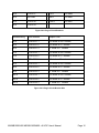
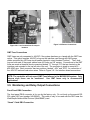
GMT Fuse Installation
Fuse holders that accommodate GMT fuses are located on the interface card mounted in the
top left side of the unit. Insert the fuse in the holder; observing the tripped indicator is correctly
oriented. These fuse holders are only connected to -48VDC if the system has been purchased
with the GMT fuse option. This option supplies -48VDC to lugs on the interface card through a
50 Amp circuit breaker located in circuit breaker Position 1. The interface card provides fuse
holders for eight fuses, labeled “F1” through “F8”, which can be used for small -48V DC loads.
Use the chart shown in Figure 3.7-3 to help determine what size fuses will carry the desired
current. Refer to Figure 3.9-1 for Interface board GMT fuse locations.
NOTE: The controller will not report GMT Fuse failures in the MX28B1200 system. Only
telecom style fuses can be monitored.
Use GMT fuses only in non-essential
applications.
FUSE
SIZE
AMBIENT TEMPERATURE
20° C
50° C
60° C
10 Amp
7 Amp
6 Amp
5 Amp
12 Amp
8 Amp
7 Amp
6 Amp
15 Amp
10 Amp
9 Amp
8 Amp
Figure 3.7-3 GMT Fuse Temperature De-rating Chart
MX28B1200/2400 MX28B1200/4800 –48 VDC User’s Manual
Page 21
3.8. Load Connections
Cable Size Considerations
The DC load cable(s) should be sized sufficiently large to limit the voltage drop from the MX28B
DC power plant to the loads per system design requirements. The cable(s) must also carry the
full load current during battery operation. During battery operation the voltage will be lower,
therefore the current will typically be higher. If assistance is required to determine the
necessary cables for the application, contact your sales representative or APC.
Circuit Breaker Connections (1 to 50 Amps)
Connections for 1 to 50 amp DC loads require standard two-hole lugs with holes for #10 screws
(810-0032) on 5/8” centers and are located directly beside the corresponding circuit breaker.
See for details.
Circuit Breaker Connections (60-100 Amps)
Circuit breakers rated for 60 to 100 amp DC are twice as wide as the smaller breakers and
therefore require two positions and a circuit breaker adapter kit. The adaptor connects the two
output lug positions to one lug. Adaptors are available with studs for #10-32 nuts on 5/8”
centers, ¼-20 nuts on ¾” centers, or ¼-20 nuts on 1” centers. The adaptor is installed directly
beside the two positions the circuit breaker is mounted on, using #10 screws provided in the kit.
The lugs (not included with the kit) fasten on to the adaptor’s studs using nuts and washers
provided in the kit. See for details.
Return Connections (1-100 Amps)
The load returns connect to the return buses located to the outside of the breaker connection
points as seen in Error! Reference source not found.. Each return bus provides 28 sets of
threaded #10-32 holes on 5/8” centers, fourteen sets of threaded ¼-20 holes on 5/8” centers
and fourteen sets of threaded ¼-20 holes on 1” centers for connection of two-hole lugs on load
return wires.
MX28B1200/2400 MX28B1200/4800 –48 VDC User’s Manual
Page 22
Figure 3.8-1 Load connections for snap-in
breakers
Figure 3.8-2 Return Connections
GMT Fuse Connections
GMT fuses are only connected to -48VDC if the system has been purchased with the GMT fuse
option. This option supplies -48VDC to lugs on the interface card through #6 AWG power
cables controlled by a 50 Amp circuit breaker located in circuit breaker Position 1. The 2-hole
lugs on both ends of the power cables have #10 holes on 5/8” centers. Connections to the GMT
fuses are made at terminal block connectors labeled “F1” through “F8” that are located on the
interface card mounted in the top left side of the unit. The connector is sized to accept #12 –
#28 AWG wire. Each connector has two positions, labeled “-48V” and “RTN”, for connection of
the -48V DC load and load return wires. Refer to Figure 3.9-1 for Interface board connections.
NOTE: The controller will not report GMT Fuse failures in the MX28B1200 system. Only
telecom style fuses can be monitored.
Use GMT fuses only in non-essential
applications.
3.9. Monitoring and Relay Output Connections
Front Panel DB9 Connection
The front panel DB-9 connector is for use by the factory only. Do not hook up the special RS232 cable (APC part number 940-0024C). This cable is only to be used with the DB-9 near the
Web/Simple Network Mail Protocol (Web/SNMP) card.
“Smart” Cable DB9 Connection
The DB9 connector on the top right hand side of the unit, behind a blank panel directly above
the controller, uses the special RS-232 cable (APC part number 940-0024C) to allow local
access through a Terminal Emulation program like HyperTerminal™ or Procomm™ .
RJ45 Ethernet Connector
The optional management card, which is behind a blank panel directly above the controller, has
an RJ-45 connector to support a TCP/IP protocol over a 10BaseT Ethernet Local Area Network
(LAN).
Relay Output Connections
There are eight alarms available that provide outputs via Form “C” relay contacts. The last two
of these are pre-assigned as the Minor and Major relay outputs. The Major relay is energized
(NO-C contacts closed) during normal (non-alarm) operating conditions; all the other relays
energize when an alarm condition occurs. The other six outputs are initially designated as
“Relay 1” through “Relay 6” (the user may assign more meaningful names if desired). The
various system alarm conditions can be assigned to any of the eight alarm outputs. There are
three sets of Wago connectors on the interface card. Two are for Output Relays and one is for
Input Relays. To attach the Output Relay wires, push down on the white spring-loaded lever;
Insert the wire and release the lever. Refer to the board layout in Figure 3.9-1 for Output Relay
connections. The relay contacts should only be used to switch resistive loads of 0.5 amperes or
less at 60 volts or less. The following shows the alarm output connection designations.
Figure 3.9-1 Interface Board
MX28B1200/2400 MX28B1200/4800 –48 VDC User’s Manual
Page 24
RELAY
OUTPUT
TERMINAL
DESIGNATION
NO-NC-C
USER ALARM NOTES
RELAY #1
RELAY #2
RELAY #3
RELAY #4
NO1-NC1-C1
NO2-NC2-C2
NO3-NC3-C3
NO4-NC4-C4
________________________
________________________
________________________
________________________
RELAY #5
RELAY #6
MINOR
MAJOR
NO5-NC5-C5
NO6-NC6-C6
NO7-NC7-C7
NO8-NC8-C8
________________________
________________________
________________________
________________________
Figure 3.9-2 Output Relay Connections
3.10. External Alarm Input Connections
Four external alarm inputs with assignable priority levels are available. These alarm inputs
respond to external dry contact closures between normally open (NO) and common (C) or
contact openings between normally closed (NC) and C.
External Alarm Source
(non-alarm state)
OPEN
CLOSED
Connect To Input
Alarm Terminals
NO-C
NC-C
Figure 3.10-1 External Alarm Input Definition
Connector J4 is located on the interface card mounted in the top left side of the unit. Refer to
Figure 3.9-1 for Interface board connections. Systems are shipped with jumper wires
connecting each NC and corresponding C contact. A jumper wire should be removed only if the
corresponding NC-C contacts are going to be used. To attach the Input Relay wires, push down
on the white spring-loaded lever; insert the wire and release the lever.
EXTERNAL
ALARM
INPUT
#1
#2
#3
#4
J4 TERMINAL
DESIGNATION
(NO-NC-C)
NO1-NC1-C1
NO2-NC2-C2
NO3-NC3-C3
NO4-NC4-C4
USER ALARM NOTES
___________________________
___________________________
___________________________
___________________________
Figure 3.10-2 External Alarm Input Connections
MX28B1200/2400 MX28B1200/4800 –48 VDC User’s Manual
Page 25
3.11.Rectifier Module Installation
WARNING: Rectifier DC output circuits would be damaged if battery were
installed incorrectly. Before rectifier installation, ensure proper battery
polarity and that the battery is isolated from the rest of the system
The rectifier modules are shipped in separate containers. Follow the procedure below to install
a rectifier module.
1) Remove the rectifier from its shipping container.
2) Remove any rectifier retaining screws from the shelf position where the rectifier is to be
installed.
3) Slide the rectifier module into the shelf between the guides until it is fully seated.
4) Fasten the rectifier in place with the rectifier retaining screw (included in literature kit with
product manual).
Since all adjustments are made from the system control unit, no rectifier adjustments are
necessary.
NOTE: All “FLOAT” – “BOOST/EQUALISE” switches (one is located on the front of each
rectifier in the system) must be set to “FLOAT” to allow the MX28B to control the output voltage
properly.
CAUTION: Rectifier fan inlet filters are available for dusty or hostile
environments. Failure to periodically check and clean filters can lead to
rectifier shutdown due to over temperature and produce power plant failure.
MX28B1200/2400 MX28B1200/4800 –48 VDC User’s Manual
Page 26
4
Commissioning and Preventive Maintenance
4.1. Pre-Commissioning Inspection
Environment
1.
2.
3.
4.
Ensure the DC system environment is suitable for operation.
Ensure that there is sufficient clearance around the system for service.
Ensure that there is no sign of damage to the DC system.
Consult with customer to disable installed customer alarms before servicing the unit.
This will allow the unit to be serviced without creating false alarms.
Electrical Installation
1.
2.
3.
4.
Ensure that the DC wiring is properly installed, sized, terminated and identified.
Ensure that the AC wiring is properly installed, sized, terminated and identified.
Ensure that the battery is properly connected to the System.
Ensure that the DC output over-current protection devices are adequate for the size of
wiring installed.
5. Ensure that the DC Positive is bonded to central office ground (- 48 volt system).
6. Note the resistance of the ground bond.
7. Note any currents flowing in the ground.
8. Record ambient temperature.
9. Verify that the battery polarity is correct.
10. If a battery disconnect device(s) is/are present, note the following for each device:
a. DC Voltage Rating.
b. DC Current Rating
c. Interrupting Current Rating
Battery Visual and Safety Inspection
1.
2.
3.
4.
5.
6.
7.
8.
9.
Check the mechanical integrity of the battery framing, racking, or cabinet.
Check that the battery framing, racking or cabinet is adequately secured to the floor.
Check compliance with seismic zone requirements.
Check the general appearance and cleanliness of the battery.
Record the manufacturer, model number, and capacity of the battery string(s) on Site
Form.
Record the batch number, date code, and serial number of each cell or mono-block, and
any other pertinent information that is available on the battery cells on the Site Form.
Check that the cell or mono-block numbering starts at the positive battery string terminal
and is correct.
Check that anti-oxidation compound is properly applied.
Visually inspect each cell for:
a. Cracks.
b. Case leaks.
c. Post- seal leaks.
d. Pressure relief valve leaks (VRLA only).
e. Case swelling (VRLA only).
f. Case swelling (VRLA only).
10. Check the torque of all battery inter- cell connector in accordance with the battery
manufacturer’s specifications.
4.2. Commissioning
Initial Set-up
1.
2.
3.
4.
Remove all rectifiers. Ensure that the float/equalise switch is on float.
Disconnect battery by removing a link in each string or opening the battery disconnects.
Check that battery voltage does not appear on the system bus.
Disconnect all loads.
AC Power Up
WARNING: The DC power plant is supplied from a nominal high voltage AC
voltage source. Keep the AC input enclosure cover in place when the system
is operational or energized
1. Verify that AC voltage is present for each rectifier at the back- plane position (Blue J2 of
0P-9131) inside the rectifier compartment. The AC input breaker for each rectifier should
be switched on and off to ensure that you have power at every rectifier and that the
breaker disconnects the rectifier.
2. Verify that all of the circuit breaker positions are labeled to the corresponding rectifier
correctly.
3. Insert all rectifiers.
4. Turn all rectifier circuit breakers on.
5. The main screen should appear on the control unit display (see Figure 5.6-1). The
display on the control unit is a 2-lines by 16-characters display. The cursor cycles below
the characters of the active selection on the display. Information shown in the second
line of Figure 5.6-1 that extends beyond 16 characters (to the right of the “S” in
“ALARMS”) can viewed on the control unit display by using the scrolling controls (refer to
Section 5.6 for operation of the control unit).
NOTE: When AC power is initially applied, there is a 60-second period during which no alarms
are reported.
MX28B1200/2400 MX28B1200/4800 –48 VDC User’s Manual
Page 28
DC Power Up:
1. Verify with a voltmeter that the dc voltage is within 0.1 Vdc of the System Voltage. If the
voltage is off adjust the R offset setting under the OEM menu. If the R Offset setting is
more than +/- 1.00 Volt dc, contact APC for a replacement controller module.
2. Adjust battery float voltage to negative (-)49 Volts.
3. Verify System Low Voltage Alarm.
4. Adjust battery float voltage to negative (-)57 Volts.
5. Verify System High Voltage Alarm.
6. Restore the battery float voltage to negative (-) 54.00 Volts or desired voltage.
Rectifier Test:
1. To verify that all rectifiers are reporting correctly to the controller, navigate through the
menu and verify that the status for every rectifier in the system is Rect (N) FF OFF.
2. Remove any rectifier and verify that you get a Minor alarm for rectifier 1 of n failure.
3. Remove a second rectifier and verify that you get a Major alarm for rectifier 2 of n failure.
LVD Test
1. Enable the LVD’s that are installed.
2. Set the LVD trip for each LVD to negative (-)56 Volts.
3. The LVD should have dropped out (opened). Verify visually or by monitoring the voltage
at the battery connection. Also, the minor alarm should be on.
4. Set LVD Trip back to negative (-)42 Volts.
5. The LVD should have closed. Verify visually or by monitoring the voltage at the battery
connection. The minor alarm should be off.
6. Ensure that the LVD parameters are set to desired value.
Battery Power Up
1. Monitor battery current and verify that it is +/- 0.1 Amps.
2. If the voltage is off adjust the S offset setting under the OEM menu.
3. Set battery maximum recharge setting by determining the entire battery string capacity
and dividing by 10 hours. This setting will recharge the battery in 10 hours.
4. Enter this value in the Max Batt Rech screen.
5. Monitor the battery current while closing the battery disconnects or installing open battery
links. Arcing can occur during this connection.
6. The voltage may drop if the maximum battery recharge current is exceeded.
7. The current should gradually decrease when the battery is nearing full charge.
MX28B1200/2400 MX28B1200/4800 –48 VDC User’s Manual
Page 29
Circuit Breaker/ Fuse Test:
1. For plug- in circuit breakers. Monitor alarm screen for circuit breaker alarm while shorting
out each pair of alarm contacts (using a pair of tweezers) on the circuit breaker interface
circuit board. Verify proper voltage at the circuit breaker common bus.
2. For fuses: Monitor alarm screen for fuse alarm while removing fuses from each position.
Verify proper voltage at fuse common bus.
3. Turn on fuses and circuit breakers as desired.
User Inputs
1. Change the user input to desired alarm via the controller for any input that will be used.
2. Exercise the alarm by causing the input to change state.
3. Verify the desired relay output on the controller module.
Output Relays:
1. Change the alarm parameter to desired relay output via the controller for any relay output
that will be used. All alarm parameters are shipped as either major or minor, but may be
changed to any of 6 output relays.
2. Program out put relay to desired major or minor alarm to complete programming.
3. Exercise the output relay by causing the alarm to change state.
4. Verify the desired relay output on the controller module.
Battery Temperature Compensation
1. Enable battery temperature compensation if desired.
2. Ensure that battery temperature probe is connected to the system and attached to the
battery.
3. Verify that the system voltage is above the float voltage if the battery temperature is
below 25 degrees C and below the float voltage if the battery temperature is above 25
degrees C.
MX28B1200/2400 MX28B1200/4800 –48 VDC User’s Manual
Page 30
4.3. Final Inspection:
1. Verify that the interior and exterior of the system is clean and free from debris.
2. Ensure all wires connected and bolts are properly tightened.
3. Ensure the following the User, Service, and Calibration parameters are set properly on
the controller (default settings are in parenthesis):
LVD (Param)
LVD1 Trip (-42.00 V)
LVD1 Reset (-48.00 V)
LVD2 Trip (-42.00 V)
LVD2 Reset (-48.00 V)
Batt (Set-alm)
Batt Disc Thr (10 A)
Batt (Param)
Batt Float (-54.00 V)
Batt Max Rech (50 A)
Batt (Comp)
Comp Method (OFF)
4. Verify on the status menu that the system is functioning correctly with no alarms.
5. Be sure to leave the site as orderly and neat as possible.
MX28B1200/2400 MX28B1200/4800 –48 VDC User’s Manual
Page 31
5
Operation
5.1. Technical Description
The MX28B-1200/2400 Power System is designed to supply safe –54 VDC primary power
through the use of up to 24 rectifier modules. One rectifier bay may be added to increase the
capacity to 48 rectifiers. The MX28B-1200/4800 Power System is designed to supply safe –54
VDC primary power through the use of up to 24 rectifier modules. Three rectifier bays may be
added to increase the capacity to 96 rectifiers. In conjunction with an external battery string, it
will supply backup power as well. The Power System Control Unit (PSCU) will monitor all
MX28B functions and provides battery management including controlled battery recharge with
temperature compensation and low voltage disconnect. Integrated DC output distribution
supports loads ranging from ¼ Amp all the way to 700 Amps. Battery recharging, temperature
compensation and low voltage disconnect are included. The controller can monitor up to 4
discrete external events with dry contact inputs.
5.2. Rectifier Management
AC Input Power
The basic component of the power system is the rectifier module, which rectifies utility AC into
nominal 48 Volts DC. Each rectifier module requires 208/220/240V AC (MRF28H54BV), or 277V
ac (MRF28H54BV50) single-phase, 50/60 Hz. A breaker installed in a remote panel should
individually protect each rectifier circuit.
DC Output Power
The DC outputs of all the rectifiers in the system are connected to a common bus that is rated to
carry the current of the entire system. The rectifier modules will equally share the entire load,
independent of the PSCU. The rectifiers will continue to provide DC power if the PSCU is
removed or fails.
Rectifier alarms reporting
The rectifier has numerous sensors inside the unit that monitor fan fail, high temperature,
high/low voltage, etc. These rectifier sensors trigger outputs that are monitored by the PSCU.
In addition rectifier current is measured inside each rectifier. The PSCU can trigger output
relays in the event of a rectifier alarm. Refer to Section 5.6 for PSCU control functions.
MX28B1200/2400 MX28B1200/4800 –48 VDC User’s Manual
Page 32
5.3. System Management
System Output Capacity
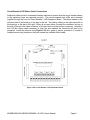
The power plant has two basic configurations:
The MX28B-1200/2400 supplies a maximum of 2400 amps or 2350 amps with N+1 redundancy.
The housing for this configuration provides two rectifier bays with integrated DC output
distribution, a control unit, and expansion bays for added DC output distribution.
The MX28B-1200/4800 supplies a maximum of 4800 amps or 4750 amps with N+1 redundancy.
The housing for this configuration provides four rectifier bays with integrated DC output
distribution, a control unit, and expansion bays for added DC output distribution. The difference
between the MX28B-1200/2400 Main Bay and the MX28B-1200/4800 Main Bay is the size and
configuration of the power bus and battery shunt. All other parts are the same for both
configurations.
System Voltage Control
The PSCU monitors and adjusts the system voltage. It uses a voltage trim input to the rectifier
to precisely control the DC output voltage. In the event of PSCU removal or failure, the shelf
rectifier controller card will control the voltage at a programmed default level. In the event of
shelf rectifier controller card failure, the individual rectifiers will default to the analog voltage level
preset with the front panel “float’ adjustment pots.
System Current
The PSCU monitors individual rectifier currents and displays total system current as a sum of
rectifier currents. Load current can be found by adding battery current to system current.
Battery Current is positive when the battery is discharging.
Sys Current + Batt current = Load Current
For example, if the battery is charging the Batt Current reading could be (–) 40 A, Sys Current
reading could be 120 A. Load Current would be:
Sys Current + Batt current = Load Current
120A + (-) 40 A = 80 Amps.
If the battery is discharging the Batt Current reading would be 40 A, Sys Current would reading
would be 40 A. Load voltage would be:
Sys Current + Batt current = Load Current
40A + 40 A = 80 Amps.
MX28B1200/2400 MX28B1200/4800 –48 VDC User’s Manual
Page 33
System Status and Alarm Reporting
The PSCU monitors system voltage using a high accuracy digital voltmeter attached to the
system bus. The PSCU monitors system temperature using a temperature IC mounted in the
PSCU. The PSCU monitors system current by summing the current reported by individual
rectifiers. The PSCU reports a number of system alarms including system high/low voltage and
high/low temperature. Refer to Section 5.6 for PSCU control functions.
5.4. DC Distribution
Distribution is included in each bay for up to 48 plug-in circuit breakers, a variety of bolt in
breaker sizes or four telecom fuses. Circuit breaker bays with three rows of bolt in circuit
breakers or fuse bays are also available. The plug-in circuit breakers can be 1 to 100 amps,
with 60-100 amp breakers requiring two positions and a circuit breaker adapter kit. When a
plug-in circuit breaker trips, a normally open switch closes and a CB alarm is reported by the
PSCU. To disconnect a load attached to a circuit breaker, move the lever to the down “OFF”
position. To disconnect a load attached to a telecom fuse pull the fuse holder straight out of the
fuse holder base.
NOTE: Plug-in Circuit breaker alarm contacts close when the circuit breaker is tripped
but not when it is turned OFF. Bolt-in Circuit breaker alarm contacts close when the
circuit breaker is tripped or turned OFF.
5.5. Battery Management
Battery Charging and Protection
Battery charging and protection are integrated into the MX28B DC power system to support the
primary function of providing power to the load. Accurate measurement of battery parameters
like voltage, current and temperature are used to maintain and protect the batteries attached to
the power plant.
Charging the battery at the correct rate reduces battery heating, increases the charge returned
to the battery and prevents excess hydrogen generation or, in the case of VRLA batteries,
possible thermal runaway. Battery Maximum Recharge Current is set to the appropriate rate,
which is usually based on the size of the battery plant in Ampere-hours.
A typical recharge current setting is battery capacity (abbreviated as “C”) divided by number of
charging hours. As an example, a “C/10” rate will basically return the battery to full charge in 10
hours. A C/8 rate is probably the highest current, which should be considered for charging
under normal circumstances.
MX28B1200/2400 MX28B1200/4800 –48 VDC User’s Manual
Page 34
Battery Temperature Compensation
The Battery Float Voltage is set to the value recommended by the battery manufacturer in order
to maintain correct battery charge at 25ºC. As temperature rises, electrochemical activity in a
battery increases. Similarly, as temperature falls, electrochemical activity in a battery
decreases. As temperature rises charging voltage should be reduced to prevent overcharge
and increased as temperature falls to prevent undercharge. The DC power system uses Battery
Temperature compensation to change output voltage to compensate for temperature changes.
This temperature compensation function is programmed into the PSCU using the compensation
parameters settings. Default settings can be changed to values recommended by the particular
battery manufacturer.
Battery/Load Low Voltage Disconnect
In order to prevent damage to the battery due to deep discharge, the DC power system has
hardware and software support for a battery or load Low Voltage Disconnect (LVD). A battery
LVD has the loads permanently attached to the rectifiers and the battery is disconnected from
the system. A load LVD has the battery permanently attached to the rectifiers and the loads are
disconnected from the system.
When the battery voltage reaches the threshold set by the LVD 1 Trip Voltage setting during
discharge, the DC power system will activate the LVD contactor to disconnect the battery or
load from the system. The LVD will remain open until AC power is restored to the system and
the bus voltage reaches the level defined by the LVD 1 Reset Voltage variable.
NOTE: The LVD is normally energized and must be commanded to open. This assures that
the LVD will remain closed even if the controller fails or is removed.
5.6. Controls and Indicators
CAUTION: The controller and the Web/SNMP card have lithium batteries.
These batteries are not field serviceable.
• Danger of explosion if battery is replaced by an incorrect type.
• Dispose of used batteries according to the manufacturer’s instructions.
Front Panel User Interface
The MX28B control unit provides a user interface designed with a hierarchical menu that can be
viewed on the 32-character (2 X 16) display by “navigating” with the “Õ” (left), “Ö” (right), “×”
(up), and “Ø” (down) arrow keys located on the front panel. The selected item on the display is
identified by the cursor cycling beneath its characters.
The “M” (modify) key and the arrow keys are used to set parameters and text to customize the
system operation for a specific application. Items that can be modified have "m+" in the upper
MX28B1200/2400 MX28B1200/4800 –48 VDC User’s Manual
Page 35
right corner of the display. If a security level higher than the one presently set is required to
modify the parameter, "s+" is displayed instead of “m+”. Status, alarms, and information
screens have "+" in the upper right corner of the display (or “#” in the case of rectifier information
screens) and cannot be modified. When AC power is initially applied, there is a 60-second
period during which no alarms are reported.
Pressing the "M" key on the front panel will change the "m+" to "M+", indicating that the
parameter can now be changed using the arrow keys. Some parameters can be changed to
other predefined selections by pressing the up or down arrow keys to display an alternative
selection. These parameters can be recognized after the “M” key is pressed by the cursor
cycling beneath the characters of the selection. For other parameters, such as text and most
numeric values, after the “M” key is pressed the cursor will be displayed under an individual
character. The right or left arrow key is used to position the cursor below the character to be
changed and the up or down arrow key is used to "spin" the digit or letter to the desired value.
When the desired changes have been made to an individual parameter screen, the “M” key is
pressed again; the “M+” changes back to “m+” and the new entry is stored in memory.
If the user plans to make any changes to system parameters, the first item that should be
verified or entered is the appropriate password for the security level required for the parameters
to be modified. Security level 2 (enter 2222 on the “PIN” screen) enables modification of all
variable system parameters. Security level 1 (enter 1111 on the “PIN” screen) permits
modification of some parameters. No security is required for viewing status items and
parameter settings. The security level password is entered through the “PIN” screen. If no front
panel keys are pressed for 60 minutes, the active security level password reverts to level 0 and
“█APC█” begins to move about the display. Pressing any key returns the display to normal and
the password must be re-entered if system parameters require changes.
Eleven LEDs are provided on the front panel of the control unit to indicate system status. Three
LEDs grouped together vertically provide overall system status; they are “MAJOR”, “MINOR”,
and “NORMAL”, indicating the presence of a major alarm, a minor alarm, or normal operation.
The other eight LEDs correspond to the active state of each of the alarm output relays and are
labeled “ALM1”∙∙∙“ALM6”, “MIN”, and “MAJ”.
MX28B-1200
+
STATUS ALARMS SYSTEM MODULES BATT PIN OEM
Figure 5.6-1 Menu Top Line
.
Parameter Locations, Descriptions, and Default Values
The location, description, and factory programmed default value for each of the MX28B
system parameters is found in the table below. The table also shows all of the status and
information screens with typical displays. The location of a parameter screen is shown in
brackets, for example: [SYSTEM/IN-RLY/RLY-MAP]. To find the parameters that can be
accessed in this category, starting from the main menu screen, do the following:
MX28B1200/2400 MX28B1200/4800 –48 VDC User’s Manual
Page 36
1. Use the right or left arrow keys to position the cycling cursor below “SYSTEM”.
2. Press the down arrow key once.
3. Use the right arrow key to position the cycling cursor below “IN-RLY”.
4. Press the down arrow key once; the cursor will be cycling below “RLY-MAP”.
5. Press the down arrow key (repeatedly if necessary) until the desired parameter screen is
displayed (there are eight parameter screens in this category).
After making any desired changes, return to the main menu press the up arrow key repeatedly.
If a parameter requires a level 1 or level 2 security access to permit changes to it, the security
level will be found in braces, i.e. Security Level {2}, in the “PARAMETER” column of the table.
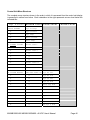
Parameter Locations, Descriptions, and Default Values
PARAMETER NAME/
DESCRIPTION
[MENU LOCATION]
DISPLAY SCREENS /
DEFAULT SETTINGS
Address 1
Security Level {1}
[SYSTEM/SETUP]
Address 2
Security Level {1}
[SYSTEM/SETUP]
Address 3
Security Level {1}
[SYSTEM/SETUP]
Alarms Item 1
{Status Only}
[ALARMS]
•
•
•
Alarms Item 16
[ALARMS]
Power plant address or identification - first line.
Address 1
m+
APC DCNS, Inc.
Power plant address or identification - second line.
Address 2
m+
11035 Switzer Av
Power plant address or identification - third line.
Address 3
Dallas, TX.
Display of up to 16 active alarms (a typical alarm
screen is shown).
Battery Current
{Status Only}
[STATUS]
Battery Discharge Alarm
Security Level {1}
[BATT/SET-ALM]
Battery Discharge Threshold
Security Level {1}
[BATT/SET-ALM]
Battery Float Voltage
Security Level {1}
[BATT/PARAM]
Battery current measured by the system controller
at the battery current shunt.
Alarm Item 1
+
Batt LV Alm Onm
•
•
•
Alarm Item 16 +
No Alarms
Batt Current
+
-15.0 A
•
•
•
Display of up to 16 active alarms (a typical alarm
screen is shown).
m+
The output relay energized if the battery discharge
current exceeds the programmed battery
discharge threshold.
An alarm is generated if the battery discharge
current exceeds this value.
Batt Disc Alm m+
Minor
One of three parameters that control the DC
output voltage. Set the Float Voltage at 25°C
battery temperature per the battery manufacturers
recommendations.
Batt Float
m+
-54.00 V
MX28B1200/2400 MX28B1200/4800 –48 VDC User’s Manual
Batt Disc Thr m+
10 A
Page 37
PARAMETER NAME/
DESCRIPTION
[MENU LOCATION]
Battery High Temperature
Alarm
Security Level {1}
[BATT/SET-ALM]
Battery High Temperature
Threshold
Security Level {1}
[BATT/SET-ALM]
Battery High Voltage Alarm
Security Level {1}
[BATT/SET-ALM]
Battery High Voltage Threshold
Security Level {1}
[BATT/SET-ALM]
Battery Low Temperature
Alarm
Security Level {1}
[BATT/SET-ALM]
Battery Low Temperature
Threshold Security Level {1}
[BATT/SET-ALM]
Battery Low Voltage Alarm
Security Level {1}
[BATT/SET-ALM]
Battery Low Voltage Threshold
Security Level {1}
[BATT/SET-ALM]
Battery Maximum Recharge
Current
Security Level {1}
[BATT/PARAM]
Battery Temperature
{Status Only}
[STATUS]
Circuit Breaker 1 Alias
Security Level {1}
[MODULES/CIRBKR/ALIAS]
•
•
•
Circuit Breaker 24 Alias
Security Level {1}
[MODULES/CIRBKR/ALIAS]
DISPLAY SCREENS /
DEFAULT SETTINGS
The output relay energized if the battery
temperature exceeds the Battery High
Temperature threshold.
Batt HT Alm
m+
Minor
Battery Temperature is temperature measured at
the battery probe. An alarm is generated if the
battery temperature exceeds this value.
Batt HT Thr
m+
70.0 C
The output relay energized if the DC output
voltage rises above the battery high voltage
threshold.
An alarm will be reported if temperature is lower
than the temperature entered.
An alarm is generated if the DC output voltage
rises above this value.
The output relay energized if the Battery
Temperature drops below the battery Low
Temperature threshold.
Batt HV Alm
m+
Minor
Battery Temperature is temperature measured at
the battery probe. An alarm is generated if the
battery temperature drops below this value.
The output relay energized if the DC output
voltage drops below the battery low voltage
threshold.
An alarm is generated if the DC output voltage
drops below this value.
Batt LT Thr
One of three parameters that control the DC
output voltage. If Battery Current surpasses the
Maximum Battery Recharge Current, the DC
output voltage will be reduced (the system limits
the charging current to this programmable value).
Battery temperature measured by the system
controller at the optional battery temperature
sensor probe.
An alternate name (alias) that can be assigned to
a circuit breaker if desired.
Batt Max Rechm+
50 A
•
•
•
An alternate name (alias) that can be assigned to
a circuit breaker if desired.
MX28B1200/2400 MX28B1200/4800 –48 VDC User’s Manual
Batt HV Thr
m+
-58.00 V
Batt LT Alm
m+
Minor
m+
0.0 C
Batt LV Alm
m+
Minor
Batt LV Thr
m+
-44.00 V
Batt Temp
+
25.2 C
Cir Bkr 1
m+
-48V
•
•
•
Cir Bkr 72
m+
-48V
Page 38
PARAMETER NAME/
DESCRIPTION
[MENU LOCATION]
Circuit Breaker 1 Tripped
Security Level {1}
[MODULES/CIRBKR/SETALM]
•
•
•
Circuit Breaker 24 Tripped
Security Level {1}
[MODULES/CIRBKR/SETALM]
Compensation High Knee
Security Level {1}
[BATT/COMP]
Compensation Low Knee
Security Level {1}
[BATT/COMP]
Compensation Method
Security Level {1}
[BATT/COMP]
Compensation Temperature
Coefficient
Security Level {1}
[BATT/COMP]
Control Unit Revision
{Status Only}
[SYSTEM/SETUP]
Date
Security Level {1}
[SYSTEM/DATE]
Display Type
{Status Only}
[SYSTEM/SETUP]
Fahrenheit Scale
Security Level {1}
[SYSTEM/SETUP]
Firmware Version
{Status Only}
[SYSTEM/SETUP]
FUSE 1 Alias
Security Level {1}
[MODULES/FUSE/ALIAS]
•
•
•
FUSE 8 Alias
Security Level {1}
[MODULES/FUSE/ALIAS]
An alarm that indicates Circuit Breaker 1 is
tripped.
•
•
•
An alarm that indicates Circuit Breaker 24 is
tripped.
DISPLAY SCREENS /
DEFAULT SETTINGS
Cir Bkr 1 Alm m+
Major
•
•
•
Cir Bkr 72 Almm+
Major
The temperature compensation high knee is the
point above which there is no additional battery
voltage compensation for further increases in
temperature.
The temperature compensation low knee is the
point below which there is no additional battery
voltage compensation for further decreases in
temperature.
One of three parameters that control the DC
output voltage. Activate “ON” or de-activate “OFF”
battery temperature compensation.
Temperature compensation coefficient between
low knee and high knee in mV/cell/°C.
(Compensation equals zero at 25°C.)
Comp Hknee
Hardware revision level of the control unit. This
parameter cannot be changed.
Cntrl Rev
+
000002
Internal system calendar date. Used as a date
stamp in the event log.
Date
m+
DEC 16 1999
Type number for the control unit display. This
parameter cannot be changed.
Display Type
+
000255
Enables selection of Fahrenheit or Celsius
temperature scale (Fahrenheit “OFF” displays
readings in °C).
Version number of the control unit firmware.
NOTE: Actual firmware version number
displayed is the current version as of the date
of manufacture. This parameter cannot be
changed.
An alternate name (alias) that can be assigned to
a FUSE Fuse 1 if desired.
Fahrenheit
•
•
•
An alternate name (alias) that can be assigned to
a FUSE Fuse 8 if desired.
•
•
•
FUSE 16
MX28B1200/2400 MX28B1200/4800 –48 VDC User’s Manual
m+
40.0 C
Comp Lknee
m+
0.0 C
Comp Method m+
OFF
Comp TC
m+
- 3.00mV
m+
OFF
FW Version
+
000189
Fuse 1
m+
-48V
m+
-48V
Page 39
PARAMETER NAME/
DESCRIPTION
[MENU LOCATION]
FUSE 1 Blown
Security Level {1}
[MODULES/FUSE/SET-ALM]
•
•
•
FUSE 8 Blown
Security Level {1}
[MODULES/FUSE/SET-ALM]
Hardware Battery Current
Alarm
Security Level {2}
[SYSTEM/SET-ALM]
Hardware Battery Temperature
Alarm
Security Level {2}
[SYSTEM/SET-ALM]
Hardware LVD Alarm
Security Level {2}
[SYSTEM/SET-ALM]
Hardware System Temperature
Alarm
Security Level {2}
[SYSTEM/SET-ALM]
Hardware System Voltage
Alarm
Security Level {2}
[SYSTEM/SET-ALM]
Input Relay 1
Security Level {1}
[SYSTEM/IN-RLY/RLY-MAP]
•
•
•
Input Relay 4
Security Level {1}
[SYSTEM/IN-RLY/RLY-MAP]
The Output Relay that is energized when FUSE
Fuse 1 is blown.
DISPLAY SCREENS /
DEFAULT SETTINGS
•
•
•
The Output Relay that is energized when FUSE
Fuse 8 is blown.
FUSE 1 Alm
m+
Major
•
•
•
FUSE 16 Alm m+
Major
The output relay energized if there is a hardware
failure in the battery current monitoring function.
Hw Batt C Almm+
Minor
The output relay energized if there is a hardware
failure in the battery temperature monitoring
function.
Hw Batt T Almm+
Minor
The output relay energized if there is a conflict
between the commanded and sensed positions of
the LVD contactor. Generally the contactor is
open when it should be closed.
The output relay energized if there is a hardware
failure in the system temperature monitoring
function.
Hw LVD Alm
m+
Minor
The output relay energized if there is a hardware
failure in the system voltage monitoring function.
Hw Sys V Alm m+
Minor
The Output Relay that is energized when an
external contact closure or opening at the Input
Relay 1 connection changes state.
•
•
•
The Output Relay that is energized when an
external contact closure or opening at the Input
Relay 4 connection changes state.
In-Rly 1 Alm m+
Ignore
Input Relay 1 Alias
Security Level {1}
[SYSTEM/IN-RLY/ALIAS]
•
•
•
Input Relay 4 Alias
Security Level {1}
[SYSTEM/IN-RLY/ALIAS]
An alternate name (alias) can be assigned to Input
Relay 1 if desired.
Lamp Test
Security Level {1}
[SYSTEM/DIAG]
Setting Lamp Test to “ON” will turn on the
“MAJOR”, “MINOR”, “NORMAL”, “MAJ”, and
“MIN” LEDs on the control unit front panel.
•
•
•
An alternate name (alias) can be assigned to Input
Relay 1 if desired
MX28B1200/2400 MX28B1200/4800 –48 VDC User’s Manual
Hw Sys T Alm m+
Minor
•
•
•
In-Rly 4 Alm m+
Ignore
In-Rly 1
m+
Input Relay 1
•
•
•
In-Rly 4
m+
Input Relay 4
Lamp Test
m+
OFF
Page 40
PARAMETER NAME/
DESCRIPTION
[MENU LOCATION]
LVD 1 or 2 Option
Security Level {1}
[MODULES/LVD/SET-ALM]
LVD 1 or 2 Reset
Security Level {1}
[MODULES/LVD/PARAM]
LVD 1 or 2 Trip
Security Level {1}
[MODULES/LVD/PARAM]
LVD Alarm
Security Level {1}
[MODULES/LVD/SET-ALM]
Model Programming
Security Level {2}
[SYSTEM/SETUP]
OEM R Gain
Security Level {2}
[OEM]
OEM R Offset
Security Level {2}
[OEM]
OEM S Gain
Security Level {2}
[OEM]
OEM S Offset
Security Level {2}
[OEM]
Output Relay 1 Alarm
Security Level {1}
[SYSTEM/OUT-RLY/RLYMAP]
•
•
•
Output Relay 6 Alarm
Security Level {1}
[SYSTEM/OUT-RLY/RLYMAP]
Output Relay 1 Alias
Security Level {1}
[SYSTEM/OUT-RLY/ALIAS]
•
•
•
Output Relay 6 Alias {1}
[SYSTEM/OUT-RLY/ALIAS]
DISPLAY SCREENS /
DEFAULT SETTINGS
Must be set to “Enable” if the unit has an LVD. If
the unit has an LVD, but it is disabled, the
controller will not disconnect the LVD.
LVD Reset (reconnect) threshold voltage.
LVD
LVD Trip (disconnect) threshold voltage.
LVD Trip
The output relay that is energized when the
controller opens the LVD. If unit has a battery
LVD, no power will be available to turn on any
Output Relays.
Model type number for the MX28B DC power
plant. Choose the MX28B-1200 if you have the
2500 Amp battery shunt. Choose the MX28B4800 if you have the 5000 Amp battery shunt.
NOTE: Changing the model number causes the
system to reinitialize.
Voltage gain adjustment for factory calibration of
system voltage readings/settings.
LVD Open Alm m+
Minor
Voltage offset adjustment for factory calibration of
system voltage readings/settings.
OEM R Offset m+
0.000 V
Current gain adjustment for factory calibration of
battery current readings/settings.
OEM S Gain
m+
1.000 A
Current offset adjustment for factory calibration of
battery current readings/settings.
OEM S Offset m+
0.0 A
Output Relay 1 Alarm can be “mapped” to activate
other output relays (“Ignore” activates no
additional relays).
Out-Rly 1 Alm m+
Ignore
•
•
•
Output Relay 6 Alarm can be “mapped” to activate
other output relays (“Ignore” activates no
additional relays).
•
•
•
Out-Rly 6 Alm m+
Ignore
An alternate name (alias) can be assigned to
Output Relay 1 if desired.
•
•
•
An alternate name (alias) can be assigned to
Output Relay 6 if desired.
Out-Rly 1
Relay
•
•
•
Out-Rly 6
Relay
MX28B1200/2400 MX28B1200/4800 –48 VDC User’s Manual
Option
m+
Enable
LVD Reset
m+
-48.00 V
m+
-42.00 V
Model
m+
MX28B-1200
OEM R Gain
m+
1.000 V
Page 41
m+
1
m+
6
PARAMETER NAME/
DESCRIPTION
DISPLAY SCREENS /
DEFAULT SETTINGS
Delay between sensing of the alarm condition and
activation of Output Relay 1. An alarm condition
must exist for longer than the delay to be
activated.
•
•
•
Delay between sensing of the alarm condition and
activation of Output Relay 6. An alarm condition
must exist for longer than the delay to be
activated.
An alternate name (alias) can be assigned to the
major Relay if desired.
Out-Rly 1 Dly m+
0 sec
An alternate name (alias) can be assigned to the
Minor Relay if desired.
Relay Minor
m+
Minor
Permanently change password (PIN) that permits
security Level 1 parameter changes - limited
access.
Permanently change password (PIN) that permits
security Level 2 parameter changes - unlimited
access.
Screen for entry of the active password (PIN).
Before any changes can be made, the correct pin
for the desires security level must be entered.
Level 0 – full read access. Level 1 –full read and
limited write access. Level 2 – full read and write
access.
The maximum rectifier communications response
time allowed before a communications failure is
declared.
PIN
m+
1111
PIN 2
m+
2222
PIN
m+
0000
The output relay energized if the rectifier
configuration differs from its stored configuration.
This occurs if a rectifier is added after
configuration.
The output relay that is energized or special
rectifier alarm group n of N that occurs when a
rectifier has been forced into the current limited
mode.
The status will be “ON” if the rectifier has been
forced into its current limited mode. NOTE: This
information can be viewed for each rectifier
installed by using the horizontal arrow keys.
A display of the DC output current for the
individual rectifier. NOTE: This information can
be viewed for each rectifier installed by using
the horizontal arrow keys.
Rect Cfg Alm m+
Minor
[MENU LOCATION]
Output Relay 1 Delay
Security Level {1}
[SYSTEM/OUT-RLY/RLYMAP]
•
•
•
Output Relay 6 Delay
Security Level {1}
[SYSTEM/OUT-RLY/RLYMAP]
Output Relay Major Alias
Security Level {1}
[SYSTEM/OUT-RLY/ALIAS]
Output Relay Minor Alias
Security Level {1}
[SYSTEM/OUT-RLY/ALIAS]
PIN 1 change
Security Level {2}
[SYSTEM/SETUP]
PIN 2 Change
Security Level {2}
[SYSTEM/SETUP]
PIN Entry
Security Level {0}
[PIN]
Rectifier Communications Fail
Timeout
Security Level {1}
[MODULES/RECT/PARAM]
Rectifier Configuration Alarm
Security Level {1}
[SYSTEM/SET-ALM]
Rectifier Current Limit Alarm
Security Level {1}
[MODULES/RECT/SET-ALM]
Rectifier Current Limit Alarm
Status
{Status Only}
[MODULES/RECT/INFO]
Rectifier Current Output Status
{Status Only}
[MODULES/RECT/INFO]
MX28B1200/2400 MX28B1200/4800 –48 VDC User’s Manual
•
•
•
Out-Rly 6 Dly m+
0 sec
Relay Major
m+
Major
RectFailComm m+
1 min
Rect CL Alm
m+
n of N
Rect 1 CL
#
OFF
Rect 1 Curr
#
24.9 A
Page 42
PARAMETER NAME/
DESCRIPTION
DISPLAY SCREENS /
DEFAULT SETTINGS
Displays the model number of the installed
rectifier. NOTE: This information can be
viewed for each rectifier installed by using the
horizontal arrow keys.
The output relay energized if Rectifier Fail 1-of-N
alarm occurs. This is a special rectifier alarm
group that signifies that one rectifier has at least
one alarm condition.
The output relay energized if Rectifier Fail 2-of-N
alarm occurs This is a special rectifier alarm group
that signifies that more than one rectifier has at
least one alarm condition.
Rectifier default output voltage if communication
with the control unit fails.
Rect 1 Desc
#
MRF28H54
The output relay that is energized or special
rectifier alarm group n of N that occurs when a
rectifier fan has failed.
The status will be “ON” if the rectifier fan has
failed. NOTE: This information can be viewed
for each rectifier installed by using the
horizontal arrow keys.
The status will be on if the rectifier output has
failed. NOTE: This information can be viewed
for each rectifier installed by using the
horizontal arrow keys.
The output relay that is energized or special
rectifier alarm group n of N that occurs when a
rectifier output has failed.
The output relay that is energized or special
rectifier alarm group n of N that occurs when the
control unit is holding a rectifier in the standby
mode.
The status will be “ON” if the control unit is holding
the rectifier in the standby mode. NOTE: This
information can be viewed for each rectifier
installed by using the horizontal arrow keys.
Setting this parameter to “Enable” will cause the
current rectifier configuration to be stored (the
display toggles back to “Disable” after entry).
The total system output current (calculated as the
sum of the individual rectifier output currents).
Rect FF Alm
m+
n of N
The output relay energized if the System
Temperature exceeds the system high
temperature threshold.
Sys HT Alm
m+
Minor
System Temperature is ambient temperature
measured inside the controller. An alarm will be
reported if temperature is higher than the
temperature entered.
Sys HT Thr
[MENU LOCATION]
Rectifier Description
{Status Only}
[MODULES/RECT/INFO]
Rectifier Fail 1-of-N Alarm
Security Level {1}
[SYSTEM/SET-ALM]
Rectifier Fail 2-of-N Alarm
Security Level {1}
[SYSTEM/SET-ALM]
Rectifier Fail Safe Voltage
Security Level {1}
[MODULES/RECT/PARAM]
Rectifier Fan Fail Alarm
Security Level {1}
[MODULES/RECT/SET-ALM]
Rectifier Fan Fail Alarm Status
{Status Only}
[MODULES/RECT/INFO]
Rectifier Fault Alarm (RFA)
Status
{Status Only}
[MODULES/RECT/INFO]
Rectifier RFA Alarm
Security Level {1}
[MODULES/RECT/SET-ALM]
Rectifier Standby Alarm
Security Level {1}
[MODULES/RECT/SET-ALM]
Rectifier Standby Alarm Status
{Status Only}
[MODULES/RECT/INFO]
Store Configuration
Security Level {1}
[SYSTEM/DIAG]
System Current
{Status Only}
[STATUS]
System High Temperature
Alarm
Security Level {1}
[SYSTEM/SET-ALM]
System High Temperature
Threshold
Security Level {1}
[SYSTEM/SET-ALM]
MX28B1200/2400 MX28B1200/4800 –48 VDC User’s Manual
Rect 1ofN Almm+
Minor
Rect 2ofN Almm+
Major
Rect Fail Safem+
-54.00 V
Rect 1 FF
#
OFF
Rect 1 RFA
#
OFF
Rect RFA Alm m+
n of N
Rect Stdby Almm+
n of N
Rect 1 Stdby
#
OFF
Store Cfg
m+
Disable
Sys Current
+
145.8 A
m+
70.0 C
Page 43
PARAMETER NAME/
DESCRIPTION
[MENU LOCATION]
System High Voltage alarm
Security Level {1}
[SYSTEM/SET-ALM]
System High Voltage
Threshold
Security Level {1}
[SYSTEM/SET-ALM]
System Low Temperature
Alarm
Security Level {1}
[SYSTEM/SET-ALM]
System Low Temperature
Threshold
Security Level {1}
[SYSTEM/SET-ALM]
System Low Voltage Alarm
Security Level {1}
[SYSTEM/SET-ALM]
System Low Voltage Threshold
Security Level {1}
[SYSTEM/SET-ALM]
System Temperature
{Status Only}
[STATUS]
System Voltage
{Status Only}
[STATUS]
Test Major Relay
Security Level {1}
[SYSTEM/DIAG]
Test Minor Relay
Security Level {1}
[SYSTEM/DIAG]
Test Relay 1
Security Level {1}
[SYSTEM/DIAG]
•
•
•
Test Relay 6
Security Level {1}
[SYSTEM/DIAG]
Test Relay Enable
Security Level {1}
[SYSTEM/DIAG]
DISPLAY SCREENS /
DEFAULT SETTINGS
The output relay energized if the System Voltage
is above the System High Voltage threshold.
Sys HV Alm
m+
Minor
System Voltage is bus voltage measured by the
controller. An alarm will be reported if voltage is
higher than the voltage entered.
Sys HV Thr
m+
-58.00 V
The output relay energized if the System
Temperature is below the System Low
Temperature threshold.
Sys LT Alm
m+
Minor
System Temperature is ambient temperature
measured inside the controller. An alarm will be
reported if temperature is lower than the
temperature entered.
The output relay energized if the System Voltage
is below the System Low Voltage threshold.
Sys LT Thr
System Voltage is bus voltage measured by the
controller. An alarm will be reported if voltage is
lower than the voltage entered.
System temperature measured within the control
unit.
Sys LV Thr
m+
-50.00 V
System output voltage measured between the
MX28B DC power plant -48V and return buses.
Sys Voltage
+
-54.00 V
Setting this parameter to “ON” de-energizes the
Major Relay and turns on the “MAJ” LED on the
control unit front panel. In normal operation Major
Relay is energized so that when a loss of –48
VDC power occurs, the relay will change state.
Setting this parameter to “ON” energizes the Minor
Relay and turns on the “MIN” LED on the control
unit front panel.
Setting this parameter to “ON” energizes Relay 1
and turns on the “ALM1” LED on the control unit
front panel.
•
•
•
Setting this parameter to “ON” energizes Relay 6
and turns on the “ALM6” LED on the control unit
front panel.
Test Maj Rly m+
OFF
This parameter must be set to “Enable” to permit
the eight output relays to be manually tested;
otherwise, the state of the relays will be per
system conditions.
Test Relay En m+
Disable
MX28B1200/2400 MX28B1200/4800 –48 VDC User’s Manual
m+
0.0 C
Sys LV Alm
m+
Minor
Sys Temp
+
26.7 C
Test Min Rly m+
OFF
Test Relay 1 m+
OFF
•
•
•
Test Relay 6 m+
OFF
Page 44
PARAMETER NAME/
DESCRIPTION
[MENU LOCATION]
Time
Security Level {1}
[SYSTEM/DATE]
Internal system clock time (24-hour format). Used
as a date stamp in the event log.
MX28B1200/2400 MX28B1200/4800 –48 VDC User’s Manual
DISPLAY SCREENS /
DEFAULT SETTINGS
Time
m+
9:00:25
Page 45
Control Unit Menu Structure
The complete menu structure shown in the order in which it is accessed from the control unit display
is presented in outline form below. Each indentation to the right represents a menu level below the
indicated title.
T o p
L e v e l
MX28B 1200
STATUS ALARMS
Second Level
Third Level
Fourth Level
+
Sys Voltage
•
Sys Current
•
Sys Temp
•
Batt Current
•
Batt Temp
MX28B 1200
+
US ALARMS SYSTEM
Alarm Item 1
•
Alarm Item 2
•
Alarm Item 3
•
•
•
•
•
•
•
Alarm Item 14
•
Alarm Item 15
•
Alarm Item 16
MX28B 1200
+
MS SYSTEM MODULE
SYS
+
SET-ALM SETUP DA
Sys HV Thr
•
•
Sys HV Alm
•
•
Sys LV Thr
•
•
Sys LV Alm
•
•
Rect Cfg Alm
•
•
Rect 1ofN Alm
•
•
Rect 2ofN Alm
•
•
Sys HT Thr
•
•
Sys HT Alm
•
•
Sys LT Thr
•
•
Sys LT Alm
•
•
Hw Sys V Alm
MX28B1200/2400 MX28B1200/4800 –48 VDC User’s Manual
Page 46
T o p
L e v e l
Second Level
Third Level
•
•
Hw Batt C Alm
•
•
Hw Batt T Alm
•
•
Hw Sys T Alm
•
•
Hw LVD Alm
•
SYS:
+
LM SETUP DATE
PIN 1
•
•
PIN 2
•
•
Address 1
•
•
Address 2
•
•
Address 3
•
•
Model
•
•
Fahrenheit
•
•
Cntrl Rev
•
•
FW Version
•
•
Display Type
•
•
•
SYS:
+
LY DATE OUT-RLY
•
SYS:
+
TE OUT-RLY IN-R
Fourth Level
Date
Time
SYS:OUT:
+
RLY-MAP ALIAS
Out-Rly 1 Alm
•
•
•
Out-Rly 2 Alm
•
•
•
Out-Rly 3 Alm
•
•
•
Out-Rly 4 Alm
•
•
•
Out-Rly 5 Alm
•
•
•
Out-Rly 6 Alm
•
•
•
Out-Rly 1 Dly
•
•
•
Out-Rly 2 Dly
•
•
•
Out-Rly 3 Dly
•
•
•
Out-Rly 4 Dly
•
•
•
Out-Rly 5 Dly
•
•
•
Out-Rly 6 Dly
•
•
•
•
SYS:OUT:
AP ALIAS
•
MX28B1200/2400 MX28B1200/4800 –48 VDC User’s Manual
+
Out-Rly 1
Out-Rly 2
Page 47
T o p
L e v e l
Second Level
Third Level
Fourth Level
•
•
•
Out-Rly 3
•
•
•
Out-Rly 4
•
•
•
Out-Rly 5
•
•
•
Out-Rly 6
•
•
•
Relay Minor
•
•
•
Relay Major
•
SYS:
+
LY IN-RLY DIAG
SYS:IN-:
+
RLY-MAP ALIAS
In-Rly 1 Alm
•
•
•
In-Rly 2 Alm
•
•
•
In-Rly 3 Alm
•
•
•
In-Rly 4 Alm
•
•
SYS:IN-:
AP ALIAS
+
In-Rly 1
•
•
•
In-Rly 2
•
•
•
In-Rly 3
•
•
•
In-Rly 4
•
SYS:
LY DIAG
+
Store Cfg
•
•
Lamp Test
•
•
Test Relay En
•
•
Test Relay 1
•
•
Test Relay 2
•
•
Test Relay 3
•
•
Test Relay 4
•
•
Test Relay 5
•
•
Test Relay 6
•
•
Test Min Rly
•
•
Test Maj Rly
MX28B 1200
+
EM MODULES BATT
MOD:
RECT CIR-BKR
+
MOD:REC:
+
SET-ALM PARAM I
Rect CL Alm
•
•
•
Rect Stdby Alm
•
•
•
Rect FF Alm
•
•
•
Rect RFA Alm
•
•
MOD:REC:
+
LM PARAM INFO
MX28B1200/2400 MX28B1200/4800 –48 VDC User’s Manual
Rect Fail Safe
Page 48
T o p
L e v e l
Second Level
•
•
•
•
Third Level
•
MOD:REC:
AM INFO
Fourth Level
Rect Fail Comm
+
Rect # Desc
•
•
•
Rect # Curr
•
•
•
Rect # CL
•
•
•
Rect # Stdby
•
•
•
Rect # FF
•
•
•
Rect # RFA
•
MOD:
+
CT CIR-BKR FUSE
MOD:CIR:
+
SET-ALM ALIAS
Cir Bkr 1 Alm
•
•
•
Cir Bkr 2 Alm
•
•
•
Cir Bkr 3 Alm
•
•
•
•
•
•
•
•
•
•
•
•
•
•
•
Cir Bkr 70 Alm
•
•
•
Cir Bkr 71 Alm
•
•
•
Cir Bkr 72 Alm
•
•
MOD:CIR:
LM ALIAS
+
Cir Bkr 1
•
•
•
Cir Bkr 2
•
•
•
Cir Bkr 3
•
•
•
•
•
•
•
•
•
•
•
•
•
•
•
Cir Bkr 70
•
•
•
Cir Bkr 71
•
•
•
Cir Bkr 72
•
MOD:
KR FUSE LVD
+
MOD:FUS:
+
SET-ALM ALIAS
FUSE 1 Alm
•
•
•
FUSE 2 Alm
•
•
•
FUSE 3 Alm
•
•
•
FUSE 4 Alm
•
•
•
FUSE 5 Alm
MX28B1200/2400 MX28B1200/4800 –48 VDC User’s Manual
Page 49
T o p
L e v e l
Second Level
Third Level
Fourth Level
•
•
•
FUSE 6 Alm
•
•
•
FUSE 7 Alm
•
•
•
FUSE 8 Alm
•
•
•
FUSE 9 Alm
•
•
•
FUSE 10Alm
•
•
•
FUSE 11Alm
•
•
•
FUSE 12Alm
•
•
•
FUSE 13Alm
•
•
•
FUSE 14Alm
•
•
•
FUSE 15Alm
•
•
•
FUSE 16Alm
•
•
MOD:FUSE:
LM ALIAS
+
FUSE 1
•
•
•
FUSE 2
•
•
•
FUSE 3
•
•
•
FUSE 4
•
•
•
FUSE 5
•
•
•
FUSE 6
•
•
•
FUSE 7
•
•
•
FUSE 8
•
•
•
FUSE 9
•
•
•
FUSE 10
•
•
•
FUSE 11
•
•
•
FUSE 12
•
•
•
FUSE 13
•
•
•
FUSE 14
•
•
•
FUSE 15
•
•
•
FUSE 16
•
MOD:
MT LVD
+
MOD:LVD:
+
SET-ALM PARAM
LVD 1 Option
•
•
•
LVD 1 Open Alm
•
•
•
LVD 2 Option
•
•
•
LVD 2 Open Alm
MX28B1200/2400 MX28B1200/4800 –48 VDC User’s Manual
Page 50
T o p
L e v e l
•
Second Level
•
Third Level
MOD:LVD:
LM PARAM
Fourth Level
+
LVD 1 Trip
•
•
•
LVD 1 Reset
•
•
•
LVD 2 Trip
•
•
•
LVD 2 Reset
MX28B 1200
+
ES BATT PIN OEM
BAT:
+
SET-ALM PARAM C
Batt Disc Thr
•
•
Batt Disc Alm
•
•
Batt HV Thr
•
•
Batt HV Alm
•
•
Batt LV Thr
•
•
Batt LV Alm
•
•
Batt HT Thr
•
•
Batt HT Alm
•
•
Batt LT Thr
•
•
Batt LT Alm
BAT:
+
LM PARAM COMP
•
Batt Float
•
•
•
BAT:
AM COMP
•
•
Comp TC
•
•
Comp HKnee
•
•
Comp LKnee
MX28B 1200
+
ES BATT PIN OEM
PIN
MX28B 1200
TT PIN OEM
OEM R Offset
Batt Max Rech
+
Comp Method
+
•
OEM R Gain
•
OEM S Offset
•
OEM S Gain
MX28B1200/2400 MX28B1200/4800 –48 VDC User’s Manual
Page 51
Front Panel LED Indicators
Major (Red)
On when Major Relay is de-energized*
Minor (Yellow)
On when Minor Relay is energized
Normal (Green)
On when no alarms are active
ALM 1 (Red)
On when Output Relay 1 is energized
ALM 2 (Red)
On when Output Relay 2 is energized
ALM 3 (Red)
On when Output Relay 3 is energized
ALM 4 (Red)
On when Output Relay 4 is energized
ALM 5 (Red)
On when Output Relay 5 is energized
ALM 6 (Red)
On when Output Relay 6 is energized
MIN (Red)
On when Minor Relay is energized
MAJ (Red)
On when Major Relay is de-energized*
* This will produce a major relay output even when all power is lost.
5.7. Alarm Outputs (Output Relays)
There are eight alarm output relays designated Relay 1 through Relay 6, Minor, and Major,
respectively. Various system parameters may be programmed to activate any of these alarm
relays when set thresholds are exceeded or specific conditions occur. The first six relays can
also be assigned a priority and routed or “mapped” to other output alarm relays. Available
assignments are “Ignore”, “Major”, “Minor”, and “Relay 1” ··· “Relay 6”. Screens for making
these assignments are located at [SYSTEM/OUT-RLY/RLY-MAP]. This feature makes it
possible for a single alarm condition to activate multiple alarm output relays including the Minor
or Major alarm relay. A user defined name or “alias” may also be assigned to each of the eight
output relay alarms. Screens for making these assignments are located at [SYSTEM/OUTRLY/ALIAS]. For information on making wiring connections to the alarm output relays refer to
Section 3.9
MX28B1200/2400 MX28B1200/4800 –48 VDC User’s Manual
Page 52
5.8. External Alarm Inputs (Input Relays)
The controller can monitor any external device that uses a switch or relay to output status
information. Connecting the external device to the input relay connections is the first step. The
four external alarm inputs (also referred to as “Input Relay Alarms”) can be assigned a priority
and routed or “mapped” to alarm output relays. Available assignments are “Ignore”, “Major”,
“Minor”, and “Relay 1” ··· “Relay 6” (do not map relay to itself or the alarm will never clear).
Screens for making the assignments are located at [SYSTEM/IN-RLY/RLY-MAP]. A user
defined name or “alias” may also be assigned to each of these input alarms. Screens for
making these assignments are located at [SYSTEM/IN-RLY/ALIAS]. For information on wiring
connections to these inputs refer to Section 3.10.
MX28B1200/2400 MX28B1200/4800 –48 VDC User’s Manual
Page 53
6
Remote Monitoring
6.1. Description
Remote monitoring and control of the DC power system is accomplished through the use of the
optional APC Network Management card. This card is a separate module mounted into the top
panel of the system controller module.
Complete documentation for the use of the management card accompanies the DC power
system in the form of a small Quick Start Guide and a CD. The CD contains electronic copies of
User’s Manuals along with the necessary software utilities to support the management function.
6.2. Physical Connections
The management card has a RJ-45 connector to support a TCP/IP protocol over a 10BaseT
Ethernet Local Area Network (LAN). The 9-pin D-shell connector uses the special RS-232 cable
(APC part number 940-0024C) to allow local access through a Terminal Emulation program like
HyperTerminal™ or Procomm™.
6.3. Command and Monitoring Protocol
Refer to the User’s Guides and associated documentation provided on the management card
CD for the details on installation and use of the various communication protocols and command
settings.
7
Preventive Maintenance
Preventive Maintenance is typically performed on a quarterly basis.
7.1. Equipment
1. 4 Digit Voltmeter.
2. Clamp-on Ampere meter.
3. Standard Insulated tools.
7.2. Inspection
Environmental Inspection
1.
2.
3.
4.
Ensure the DC system environment is suitable for operation.
Ensure that there is sufficient clearance around the system for service.
Ensure that there is no sign of damage to the DC system.
Contact monitoring personnel or disable system alarms before servicing the unit. This
will allow the unit to be serviced without creating false alarms.
System Visual and Safety Inspection
WARNING: Hazardous energy levels are present on bare conductors
in the -48VDC distribution connection area of the plant. Accidental
shorting of distribution conductors can cause arcing and high currents
that can cause serious burns or other physical harm.
It is
recommended that:
• Any jewelry, rings or watches be removed while working on this
equipment.
• Handles of all wrenches, screwdrivers, cutters and pliers are
insulated.
1.
2.
3.
4.
Ensure that the DC wiring is properly installed, sized, terminated and identified.
Ensure that the AC wiring is properly installed, sized, terminated and identified.
Ensure that the battery is properly connected to the System.
Ensure that the DC output over-current protection devices are adequate for the size of
wiring installed.
5. Ensure that the DC Positive is bonded to central office ground (- 48 volt system).
6. Note the resistance of the ground bond.
7. Note any currents flowing in the ground.
8. Record ambient temperature.
9. Verify that the battery polarity is correct.
10. If battery disconnect devices are present, note the following for each device:
a) DC Voltage Rating.
b) DC Current Rating
c) Interrupting Current Rating
Battery Visual and Safety Inspection
1. Check that the battery temperature probe is firmly attached to the battery.
2. Check the mechanical integrity of the battery framing, racking, or cabinet. Tighten where
necessary.
3. If there is a battery disconnect device fitted, ensure that it is properly connected and
protected.
4. Check the general appearance and cleanliness of the battery. Clean if necessary. Use
only approved cleaning materials.
5. Visually inspect each cell for the following, and clean and neutralize if necessary.
Document discrepancies on Site form accordingly.
a. Cracks.
b. Case leaks.
c. Post-seal leaks.
d. Pressure relief valve leaks (VRLA only).
e. Case swelling (VRLA only).
f. Terminal corrosion and connector corrosion.
6. Check the torque of all battery inter-cell connector in accordance with specifications. Retorque if necessary (annual only).
7. Measure and record ambient temperature.
7.3. Test
System Voltage Test
Verify with a voltmeter directly attached to the DC bus that the system voltage is correct. If the
voltage is off by more than 0.1V recalibrate the controller with the OEM/R Offset setting.
System voltage should also agree with the battery float voltage set up in the battery parameters
section. The system may be off because of battery temperature compensation or battery
recharging.
Rectifier Current Test
1. Insert voltmeter probe between I+ and common jack on front of each rectifier.
2. Record current for each rectifier using the formula – Voltage X 10amps/volt.
3. Rectifier current displayed under Rectifier/Info should agree with the recorded current.
MX28B1200/2400 MX28B1200/4800 –48 VDC User’s Manual
Page 56
Rectifier Current Share Test
Verify that the highest rectifier current and the lowest current are within 5 amps.
System Current Test
Verify the System current equal to the total of the rectifier currents. System current should
equal the total current of the loads as well as any battery current.
Rectifier Alarm Test
1. Verify that all of the rectifiers report RFA Alarm is off.
2. Verify that the battery voltage reading on the voltmeter is negative (-)54.00 + 0.02Volts.
3. Remove 1 rectifier and verify that you get a Minor alarm for Rect 1 of n failure on the
controller and the customer remote alarm panel.
4. Remove the second rectifier and verify that you get a Major alarm for Rect 2 of n failure
on the controller and the customer remote alarm panel.
5. After the fan has completely stopped spinning, insert a plastic pen or plastic screwdriver
into the fan blade of one of the rectifiers and reinsert both rectifiers
6. Verify that you get the fan fail alarm on controller and the customer remote alarm panel.
7. Remove the fan fail device.
System Temperature Test
Verify that the system temperature is correct.
Battery Current Test
1. Measure the battery current with a clamp-on meter.
2. Verify that the battery current is below 5 amps.
3. Verify that the displayed battery current is within + 5 amps. Adjust OEM/S Offset if
required.
4. Determine the total battery capacity at the site:
Cells connected in series make up a string, and the capacity is determined by the
capacity of a single cell. Add amp/hour capacity for all strings connected in parallel.
Enter the total battery capacity in the appropriate box on the Site Form.
5. Determine the Max. Batt. Recharge rate:
Divide Total battery capacity by 20 hours and enter it in the appropriate box on the Site
Form.
6. Verify that the Max. Batt. Recharge rate is set to the calculated value.
7. Remove AC power to the rectifiers purposely causing the battery discharge alarm to
come on.
8. Verify that the System Current is 0 + 5 amps.
9. Verify that the battery current is within 5 % of the system current recorded previously.
10. Verify that the Battery Discharge Alarm is on.
11. Restore AC power to the rectifiers.
MX28B1200/2400 MX28B1200/4800 –48 VDC User’s Manual
Page 57
Battery Temperature Test
If the battery teperature probe is used in this system, verify that the battery temperature is
correct.
LVD Test
1. Verify that the Battery Float voltage is set to negative (-) 54.00 Volts via the control panel
and verify the temperature compensation setting is at its default setting (disabled).
2. Enable the LVD’s that are installed.
Note: In single-bay systems, only LVD1 is used. In multi-bay systems LVD1 and LVD2
are used in parallel.
3. Ensure that the LVD parameters are set to proper value.
4. Install rectifiers and restore AC power.
5. Set the LVD Trip to –56.00 Volts.
6. The LVD should have dropped out (opened). Verify it by monitoring the voltage at the
battery connection.
7. Verify that the LVD Open Alarm is registered on the controller and at the customer
remote alarm panel.
8. Reset the LVD Trip to negative (-) 42Volts.
9. Verify that the LVD Open Alarm has been removed.
Battery Preventive Maintenance Procedure
The purpose of the preventive maintenance is to ensure that the battery is in good, working
condition. The observations, measurements, and tests performed are designed to determine
the “state of health” of the battery. It will also allow for the prediction of future performance and
preempt possible failure.
1. Measure the float charge voltage.
a. At the power bay bus.
b. At the battery.
c. Reset voltage if necessary.
2. Measure the float current on each battery cable. If it is fluctuating, measure maximum
and minimum.
3. Measure the AC ripple voltage at the battery.
4. Using an Alber Cellcorder, measure the float voltage of each cell or monoblock. Record
the battery memory location allocated on the Cellcorder.
5. Using an Alber Cellcorder, perform a load test on each cell or monoblock and measure
the internal cell resistance and inter-cell resistance of each cell or monoblock.
6. Measure and record the specific gravity of each cell using an individual hydrometer or
Cellcorder attachment hydrometer (VLA only).
7. Ensure that the electrolyte level is adequate. Add approved water where necessary (VLA
only).
8. Measure and record the temperature of the electrolyte of each cell (VLA only).
MX28B1200/2400 MX28B1200/4800 –48 VDC User’s Manual
Page 58
9. Ensure that all protective covers are replaced and that the battery is electrically nonhazardous to personnel that could be working in the vicinity. Detail any discrepancies.
10. Download the Cellcorder to a PC and create a data file for each battery string. Keep a
copy of the results on disk.
7.4. Final Inspection:
6. Verify that the interior and exterior of the system is clean and free from debris.
7. Ensure all wires connected and bolts are properly tightened.
8. Ensure the following the User, Service, and Calibration parameters are set properly on
the controller (default settings are in parenthesis):
LVD (Param)
LVD1 Trip (-42.00 V)
LVD1 Reset (-48.00 V)
LVD2 Trip (-42.00 V)
LVD2 Reset (-48.00 V)
Batt (Set-alm)
Batt Disc Thr (10 A)
Batt (Param)
Batt Float (-54.00 V)
Batt Max Rech (50 A)
Batt (Comp)
Comp Method (OFF)
9. Verify on the status menu that the system is functioning correctly with no alarms.
10. Be sure to leave the site as orderly and neat as possible.
MX28B1200/2400 MX28B1200/4800 –48 VDC User’s Manual
Page 59
8
Specifications
The overall system specifications can vary, depending upon the number of rectifier modules.
Note that some specification items are provided on a “per rectifier” basis and must be combined
or totaled for a give system configuration.
8.1. AC Input
1MRF28H54BV Rectifiers
Nominal Input Voltage
208, 230 VAC
Input Voltage Range
176 – 264 VAC
AC Frequency Range
45 – 65 Hz
Apparent Power Factor
99% Typical, 98% Minimum
Maximum Input Current (per Rectifier)
13.9 Amps @ 230V AC
1MRF28H54BV50 Rectifiers
Nominal Input Voltage
277 VAC
Input Voltage Range
176 – 293 VAC
AC Frequency Range
45 – 65 Hz
Apparent Power Factor
99% Typical, 98% Minimum
Maximum Input Current (per Rectifier)
11.0 Amps @ 277V AC
8.2. DC Output (with either 1MRF28H54BV Rectifiers and
1MRF28H54BV50 Rectifiers)
Nominal Output Voltage (factory set)
54.5 VDC
Operating Voltage Range
44 – 58 VDC
Rated Output Current (per Rectifier)
50 A
Rated Output Power (per Rectifier)
2800 W (45ºC)
Efficiency
91% Typical
8.3. Controls and Indicators
Rectifiers
Input Healthy LED
AC power present.
Output Healthy LED
DC output voltage within operating range (-39.5 to –59.5 VDC).
Output Current LED
On when rectifier is supplying current.
Thermal Control LED
On when one of three internal sensors is above 90ºC
Current Limit LED
On when rectifier is in current limit.
Overvolts LED
On when rectifier is above 57 Volts. (Must be powered down to reset)
Overtemp LED
On when one of three internal sensors is above 130ºC. Power
Conversion is inhibited.
Fan fail LED
On when Fan is running too slow.
Standby LED
On when the unit is in the standby mode. No output power is
produced. Rectifier is still active
+V Test Point
Rectifier Voltage can be measured with a voltmeter between COM
and +V.
COM Test Point
Negative reference for both +V and +I
+I Test Point
Rectifier Current can be measured with a voltmeter between COM
and +I.
MX28B1200/2400 MX28B1200/4800 –48 VDC User’s Manual
Page 61
Float / Boost/Equalize
Switch
Used to Control voltage on systems without a PSCU
Float Trim Pot
The float pot is used to adjust the default float voltage (54.5 VDC).
Boost/Equalize Trim
Pot
The boost/equalize pot is used to adjust the default boost equalize
voltage (57.5 VDC).
Power Shelf Control Unit
Major (Red)
On when Major Relay is de-energized*
Minor (Yellow)
On when Minor Relay is energized
Normal (Green)
On when no alarms are active
ALM 1 (Red)
On when Output Relay 1 is energized
ALM 2 (Red)
On when Output Relay 2 is energized
ALM 3 (Red)
On when Output Relay 3 is energized
ALM 4 (Red)
On when Output Relay 4 is energized
ALM 5 (Red)
On when Output Relay 5 is energized
ALM 6 (Red)
On when Output Relay 6 is energized
MIN (Red)
On when Minor Relay is energized
MAJ (Red)
On when Major Relay is de-energized*
MX28B1200/2400 MX28B1200/4800 –48 VDC User’s Manual
Page 62
8.4. Mechanical
Dimensions
84” high x 26” wide x 26” deep
Weight
Housing
400-600 lbs. (181-272 Kg)
Rectifier (each)
11 lbs (5Kg)
Color
Dawn Gray
Mounting
Floor Mounting
8.5. Environmental
Ambient Temperature
Humidity
Altitude
(Operating)
-45ºC to +55ºC (+65ºC with reduced power output)
(Storage)
-45ºC to +85ºC
(Operating)
0 – 85% RH (non-condensing)
(Storage)
0 – 95% RH (non-condensing)
(Operating)
3000 m (9840 ft.)
(Storage)
10000 m (39370 ft.)
8.6. Compliance
NEBS
Level 3
Safety
UL 1950
EMC
FCC Part 15 Class A
MX28B1200/2400 MX28B1200/4800 –48 VDC User’s Manual
Page 63
9
APC Worldwide Customer Support
Customer Support for this or any other APC product is available at no charge. You can contact
APC Customer Support in any of the following ways:
•
Use an APC web page to find answers to frequently asked questions (FAQs), to access
documents in the APC Knowledge Base, and to submit customer support requests.
o http://www.apc.com (Corporate Headquarters)
Connect by links to APC web pages for specific countries and regions, each of
which provides customer support information.
o http://www.apc.com/support/
Submit customer support requests.
•
Contact Local or regional APC Customer Support by telephone or e-mail.
o For e-mail addresses and local, country-specific, customer support telephone
numbers worldwide, refer to: http://www.apc.com/support/contact.
o For e-mail addresses and technical support telephone number of major APC
regional customer support centers, use the following list:
•
US and Canada
(Toll Free)
+1 (800) 800-4272
(1-800-800-4APC)
Worldwide
(Toll Call)
+1 (401) 789-5735 (US)
Contact the APC representative or other distributor from whom you purchased your APC
hardware device or APC software application for information on how to obtain local
customer support.
MX28B1200/2400 MX28B1200/4800 –48 VDC User’s Manual
Page 64
10
Limited Product Warranty
The limited warranty provided by American Power Conversion Corporation ("APC") in this Statement of Limited Factory
Warranty applies only to Products Buyer purchases for your commercial or industrial use in the ordinary course of Buyer's
business.
APC PRODUCTS COVERED ("Product or Products"):
MX281200/2400
MX281200/4800
Terms of Warranty:
APC warrants that the Product shall be free from defects in materials and workmanship, for a period of two (2) years from the date of
shipment.
Warranty Procedure
If initial physical inspection results in identification of a material or workmanship flaw(s) that could impair Product performance as defined by
APC’s electrical and physical specification in effect at the time of shipment, and if this flaw(s) is not due to transportation damage or installation
abuse, contact APC or call the 24-hour emergency number, (800) 800 4APC, to request assistance.
You will be provided either a) an RMA number with instructions for return of the equipment or component(s) to
the APC factory service center, FOB destination, freight pre-paid, for examination, or b) for non-returnable
systems and equipment, notice to wait until an APC authorized service representative arrives at the site to
inspect the equipment. Repaired or advance replacement modules or circuit components will normally be
available within 24 to 48 hours of receipt of equipment or RMA.
Warranty Obligations - Repair or Replacement
If, during the warranty period, the Product is found to be physically or electrically faulty due to defective materials or workmanship, the
defective Product(s) or component(s) will be repaired or replaced at the sole option of APC. If the procedure outlined above for
contacting APC immediately after identifying a material or workmanship flaw(s) that could impair Product performance has been
properly followed, such repair or replacement of Product(s) or component(s) shall include all charges for replacement materials or
repair labor. Costs incurred for replacement installation including, but not limited to, installation equipment, travel expenses of an APC
representative(s), and costs of installation material transportation expenses are not included as a part of this warranty. Any replacement
components or materials furnished under this warranty may be new or factory remanufactured. THIS WARRANTY DOES NOT COVER
CONSUMABLES OR PREVENTATIVE MAINTENANCE ITEMS. REPAIR OR REPLACEMENT OF A DEFECTIVE PRODUCT OR
COMPONENT THEREOF DOES NOT EXTEND THE ORIGINAL WARRANTY PERIOD.
Exclusions and Limitations
This Warranty is extended to the first person, firm, association or corporation for whom the APC Product specified herein has been
bought. This Warranty is not transferable or assignable without the prior written permission of APC.
This limited warranty does not cover damage due to external causes, including accident, abuse, misuse, servicing not authorized by
APC, usage not in accordance with Product instructions, failure to perform preventative maintenance, and problems cause by use of
parts and components not supplied by APC. This limited warranty does not apply to Products from which the serial numbers have been
removed, or to conditions resulting from improper use, accidents, external causes, including installation, relocation of hardware, service
or modifications not performed by APC or its authorized service providers, or operation outside the environmental parameters specified
for the Product. APC does not warrant that the operation of any Product will be uninterrupted or error free. Warranty service may not be
performed if APC or other suppliers reasonably believe conditions at the Buyer's site represent a safety or health risk.
THERE ARE NO WARRANTIES, EXPRESS OR IMPLIED, BY OPERATION OF LAW OR OTHERWISE, OF PRODUCTS SOLD,
SERVICED OR FURNISHED UNDER THIS AGREEMENT OR IN CONNECTION HEREWITH. APC DISCLAIMS ALL IMPLIED
WARRANTIES OF MERCHANTABILITY, SATISFACTION AND FITNESS FOR A PARTICULAR PURPOSE. APC’S EXPRESS
WARRANTIES WILL NOT BE ENLARGED, DIMINISHED, OR AFFECTED BY AND NO OBLIGATION OR LIABILITY WILL ARISE
OUT OF, APC’S RENDERING OF TECHNICAL OR OTHER ADVICE OR SERVICE IN CONNECTION WITH THE PRODUCTS. THE
FOREGOING WARRANTIES AND REMEDIES ARE EXCLUSIVE AND IN LIEU OF ALL OTHER WARRANTIES AND REMEDIES.
THE WARRANTIES SET FORTH ABOVE, CONSTITUTE APC’S SOLE LIABILITY AND YOUR EXCLUSIVE REMEDY FOR ANY
BREACH OF SUCH WARRANTIES. APC’S WARRANTIES RUN ONLY TO YOU AND ARE NOT EXTENDED TO ANY THIRD
PARTIES. IN NO EVENT SHALL APC, ITS OFFICERS, DIRECTORS, AFFILIATES OR EMPLOYEES BE LIABLE FOR ANY FORM
OF INDIRECT, SPECIAL, CONSEQUENTIAL OR PUNITIVE DAMAGES, ARISING OUT OF THE USE, SERVICE OR INSTALLATION,
OF THE PRODUCTS, WHETHER SUCH DAMAGES ARISE IN CONTRACT OR TORT, IRRESPECTIVE OF FAULT, NEGLIGENCE
OR STRICT LIABILITY OR WHETHER APC HAS BEEN ADVISED IN ADVANCE OF THE POSSIBILITY OF SUCH DAMAGES.