1
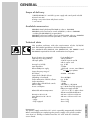
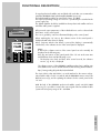
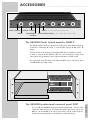
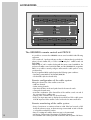
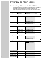
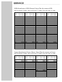
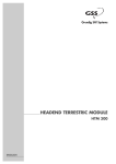
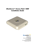
PGT 8
FESSIONAL
PROFESSIONAL
19 ” UNIT
PR
Grundig SAT Systems
CONTENTS
3
________________________________________________________________________
General
Scope of delivery
Available accessories
Technical data
4
At a Glance
Components and connectors
The control panel
6
Functional Description
The PROFESSIONAL 19 ” unit PGT 8
8
Equipping the 19” Unit
Operation with twin LNBs
Installing and connecting satellite boxes
9
Installation into Rack Systems
Installation
10
Operation in Rack Systems
Aeration, safety
11
Accessories
GRUNDIG GaAs hydrid amplifier PAMP 4
GRUNDIG professional universal panel PUP 1
GRUNDIG professional remote control unit PRCU 8
GRUNDIG professional satellite control unit PSCU 6000
14
Overview of GRUNDIG PROFI Boxes
15
Connection Example
Service (at the end of this user manual)
Channel/frequency tables
2
GENERAL
____________________________________________________________________________
Scope of delivery
1
4
4
1
PROFESSIONAL 19 ” unit PGT 8, power supply and control panel included
Prestole nuts M 6
fixing screws M 6 x16mm with plastic washers
user manual
Available accessories
GRUNDIG GaAs hybrid amplifier PAMP 4, order no. GAH4600
GRUNDIG professional remote control unit PRCU 8, order no. GAH4400
– including the GRUNDIG PC program PRCU
GRUNDIG professional satellite control unit PSCU 6000, order no. GAH4500
GRUNDIG professional universal panel PUP 1, order no. GAH7600.
Technical data
This product conforms with the requirements of the 73/23/EC
and 89/336/EC guidelines of the European Council.
The standards EN 50083-2, EN 50083-2/A1, EN 50083-1 and
EN 60065 required for the CE certification are kept to.
Passage loss (9-fold):
Input impedance:
Remote LNB power supply:
Output frequency range of
RF collector:
Output level of the RF collector
(depending on box fitted):
Output attenuation of the RF collector:
Output impedance:
Setting range of the RF level controls:
Mains voltage:
Power consumption:
Admissible ambient temperature:
Dimensions W x H x D:
Inner dimensions W x H x D:
Weight:
– empty
– fully euqipped
for 8 satellite boxes
950–2150 MHz
2 SAT IF inputs A and B
with 9 outputs each
typ. 16 dB
75 Ohm
+18V/total current max.500mA
ј for both input splitters
48 MHz ... 865 MHz
about 80 dBµV
typ. 18 dB
75 Ohm
– 20 dB
220 –240 V~; 50/60 Hz
typ. 120 W when fully equipped,
LNB power supply included
– 10 °C to + 50 °C; without humidification and dehumidification
482 mm x 356 mm x 254 mm
448 mm x 356 mm x 251 mm
about 11 kg
about 19 kg
Important!
The power supply unit of the 19” unit is especially magnetically shielded.
When exchanging or replacing the power supply unit, please make
sure that it is always installed into the 19” unit with the shielded
cover fitted.
ENGLISH
Plug-in locations (not equipped):
Input frequency range (SAT IF):
SAT input splitter:
3
AT A GLANCE
________________________________________________________________
BE–Remote
V . 21
PROFESSIONAL
19
18
17
18 V
max. 250 mA
1
2 3 4 5 6
7 8
9
LNC-Versorgung
INPUT
OUTPUT
8
1
2 3 4 5 6
7 8
9
20
950 - 2150 MHz
18 V
max. 250 mA
8
PGT 8
16
GAH 3100
220-240V~ 50/60Hz
Made in Germany
7
6
1
2
3
4
5
6
7
8
1
2
2
15
14
3
C107
L104
C107
L104
BU102
BU103
BU104
BU105
BU106
BU107
BU108
BU109
13
12Vј1A
24Vј0,1A
18Vј0,3A
18Vј0,3A
12
4
1
11
2
2
5
4
6
7
8
9
10
AT A GLANCE ___________________________________________________________________________
Components and Connectors
1
2
3
4
5
6
7
8
9
ßI
ß?
ß`
ßQ
ßW
ßE
Fixing screws for the satellite boxes.
Fixing holes of the 19 ” unit.
Plug-in locations for 8 satellite boxes, or for 7 satellite boxes and one
professional hybrid amplifier PAMP 4.
8 level controls for the satellite boxes’ output signal;
setting range: 0 dB to --20 dB.
SAT input splitter (F-sockets): 2 inputs A and B,
9 outputs per input (F-sockets), passage loss: typ. 16 dB.
Fixing holes, left, for one satellite box.
Fixing holes, right, for the professional hybrid amplifier PAMP 4.
Two spare screws for the fixation of the satellite boxes.
Type plate with pinning of the input splitter.
Power supply connector; accessible from the bottom.
Opening for a ground terminal: make the ground connection of the unit’s
frame according to DIN EN 50083/1, VDE 0855, Part 1.
Three openings for feed-through elements, e.g. IEC or F feed-through
sleeves.
Two plugs for the LNB supply voltage
(+18 V/ max. 500 mA ј ) for both LNBs.
RF socket of the output collector. This output socket is located on the back
of the 19 ” unit.
25-pin connector for the connection of a second 19 ” unit if the two 19 ” units
are to be controlled via one control panel only.
Control panel with illuminated display; behind it the power supply unit.
The control panel
ßR
The buttons on the control panel
» MULTI « (multi-function):
In the »OUTPUT« menu: output channel display of the boxes.
In the »AUDIO« menu: display of the main sound carrier and the sound
sub-carriers.
»MODE«:
Select: to next menu item.
Reset: back to access menu.
»VIDEO«: direct access to the »VIDEO« (video amplitude) menu.
»AUDIO«:direct access to the »AUDIO« (select audio frequency ) menu.
» ľ ı « (cursor functions):
select settings; move the cursor in the display ( _ ) to the left or right.
» + / – «: change settings.
LED (orange), illuminated during operation.
Display contrast control.
2-line LC display, illuminated.
9-pin Sub-D socket »RS-232« (cf. page 7 ).
Serial interface, input socket for software update.
ENGLISH
ßT
ßZ
ßU
´I
»M« (memory): save settings.
5
FUNCTIONAL DESCRIPTION
___________________________
The PROFESSIONAL 19 ” unit PGT 8
This 19 ” unit is the basic unit of a modular system for the reception and conversion of analog satellite broadcasts (radio and TV), digital satellite broadcasts
(radio and DVB TV = Digital Video Broadcasting), and terrestrial radio and TV
broadcasts.
It is provided for the installation of medium-sized and large broad-band cable
systems.
Important!
With this 19“ unit, only the signals of GRUNDIG PROFESSIONAL satellite boxes
can be processed.
An overview of the PROFI satelllite boxes which can be fitted into this basic unit
is to be found on the page 14 of this user manual.
As this 19“ unit is a modular system, it is possible to equip it with up to 8 satellite
boxes which are fitted into its plug-in locations.
Depending on the satellite boxes fitted, up to 16 analog/digital TV broadcasts,
or 16 signals from external audio/video sources, or 32 FM broadcasts can be
processed.
1
2
3
4
5
6
7
After connecting the 19“ unit to the mains voltage, all boxes are supplied with the
required operating voltages by a switched-mode power supply unit via the plugin connectors on the contact rail.
The central control panel is connected via I2 C bus lines (SDA, SCL) with the
boxes.
8
C107
L104
C107
L104
BU102
BU103
BU104
BU105
BU106
BU107
BU108
BU109
12Vј1A
24Vј0,1A
18Vј0,3A
18Vј0,3A
The passive input splitter provides highest flexibility when selecting signals with
horizontal or vertical polarization.
The professional satellite boxes are connected to the two inputs A and B of the
input splitter.
The two inputs can be operated from a remote voltage supply, that is, the LNBs
can be supplied with an operating voltage of +18 V and a total current of max.
500mA ј. Each of the two inputs A and B has nine outputs.
All RF output signals of the boxes are unified in the RF output collector, and then
passed on to the RF »OUTPUT« socket of the 19“ unit. The RF output level of
about 80 dBµV depends on the boxes fitted.
Note:
The RF »OUTPUT« socket is located on the back of the 19 ” unit (see figure
opposite).
At the factory, the output level controls of the 19“ unit are set to maximum output
level for the boxes.
Please adjust the output level of the individual boxes with the associated level
controls on the front panel of the 19“ unit to the following values:
For analog TV broadcasts to about 70 to 80 dBµV.
For digital TV broadcasts (64 QAM) about 6 to 10 dB lower than for analog TV
broadcasts.
For FM radio broadcasts about 10 dB lower than for analog TV broadcasts.
6
FUNCTIONAL DESCRIPTION _____________________________
If several professional satellite units are linked with each other, we recommend to
install the GRUNDIG GaAs hybrid amplifier PAMP 4 (accessory).
The hybrid amplifier enables an output level of max. 115 dBµV.
The required operating voltage of +24 V ј is provided by the switched-mode
power supply unit.
The hybrid amplifier should be installed into that professional satellite unit from
which the cable system is supplied.
V . 21
PROFESSIONAL
All input and output parameters of the individual boxes can be selected with
the buttons on the control panel.
The user is guided by a two-line illuminated display on the control panel.
When switching the 19“ unit on, the software version of the control panel is
briefly indicated in the 2-line LC display.
About 5 minutes after the last button is pressed, the display is automatically
switched off, or the software version of the control panel is displayed.
Note:
If desired, the software version of the control panel can also manually be
displayed in the following way:
Press any two buttons on the control panel of the 19“ unit at the same time
and hold them down until the following occurs:
– The display turns dark, and then, after several seconds, the software
version, e.g. V.21, is displayed.
The software version of the GRUNDIG satellite products basic satellite units
and satellite boxes can be donwnloaded from the following Internet address:
http://www.grundig.de/produkte/sat/mehrt.html
The 9-pin Sub-D socket »RS-232« is a serial interface for the remote configuration with the help of a PC or notebook and the GRUNDIG remote control unit
PRCU 8 (accessory), and for updating the software for the control panel of the
19“ unit.
With the help of the GRUNDIG professional satellite control unit PSCU 6000
(accessory), it is possible to monitor the output signal of the broad-band cable
system in the frequency range of 47 – 862 MHz.
ENGLISH
BE–Remote
7
EQUIPPING THE 19 ” UNIT
_____________________________
Operation with twin LNBs
In order to adjust the vertical polarization when twin LNBs are connected, it is
necessary to disconnect the voltage supply plug (LNB voltage: +18 V/total current
max.500 mA ј ) of the RF input concerned (A or B) on the chassis board of the
19“ unit (see Fig. opposite).
C107
L104
C107
L104
BU109
12Vј1A
24Vј0,1A
18Vј0,3A
18Vј0,3A
2 x LNB supply voltage
(via the SAT inputs A and B)
Installing and connecting satellite boxes
Attention!
Before installing or replacing the hybrid amplifier, a professional satellite box, or the power supply unit, it is absolutely
necessary to disconnect the power supply plug of the 19“ unit
from the wall outlet.
The power supply unit of the 19” unit is especially magnetically
shielded.
When exchanging or replacing the power supply unit, please
make sure that it is always installed into the 19” unit with the
shielded cover fitted.
1 Install and connect the professional satellite boxes in the 19“ unit according to
the instructions given in their user manuals.
08
BU109
12Vј1A
24Vј0,1A
18Vј0,3A
18Vј0,3A
Note:
If the hybrid amplifier PAMP 4 (accessory) is to be installed intead of a
satellite box in the plug-in location 8 of the19“ unit, it is necessary to disassemble beforehand the respective axle carrier with the associated axle for
the output level control (see Fig. opposite).
2 Install the hybrid amplifier according to the instructions given in its user
manual into the 19“ unit. When this is done, screw the fixing screws into
the right fixing holes in the holding frame.
Connect the hybrid amplifier.
For installing the hybrid amplifier, disassemble the axle support and axle.
8
INSTALLATION INTO RACK SYSTEMS
__
Installation
The 19“ unit has been designed for installation into 19“ rack systems.
448
25
4
Installation material supplied:
4 Prestole nuts M 6
4 fixing screws M 6 x16 mm
3
4
5
6
BU105
BU106
BU107
7
8
C107
L104
C107
L104
BU102
BU103
BU104
BU108
BU109
12Vј1A
24Vј0,1A
18Vј0,3A
18Vј0,3A
482
88 HU
HE
2
37,7
Precondition:
The rack system is completely assembled, the support elements for placing
the 19“ unit are already installed.
The total installation height of a 19“ unit is 8 HU (= height units, see Fig.
opposite). 8 height units correspond to about 356 mm.
1 Fit the four Prestole nuts accurately into the frame of the rack system (see Fig.
opposite).
1
2
3
4
5
6
BU105
BU106
BU107
7
2 Insert the 16“ unit into the rack system then fix it with the enclosed screws
(see Fig. opposite).
8
C107
L104
C107
L104
BU102
BU103
BU104
BU108
BU109
12Vј1A
24Vј0,1A
18Vј0,3A
18Vј0,3A
Important!
It is absolutely necessary to make sure that the fixation in the rack system is
able to carry the high weight of the 19“ unit(s).
Before putting the rack system into operation, ground it according to the
regulations DIN EN 50083/1, VDE 0855, Part 1.
3 Connect the mains plug of the 19 ” unit with a wall outlet (220-240 V~,
50/60 Hz).
Note:
The 19“ unit is only completely separated from the mains
voltage by pulling the power supply plug.
4 Set up the satellite boxes and the hybrid amplifier according to the instructions given in their user manuals.
ENGLISH
279,4
1
9
OPERATION IN RACK SYSTEMS
________________
Aeration, safety
Attention!
When installing the 19“ unit into a rack system, it is absolutely
necessary to make sure that the ambient and operating temperatures do neither fall below nor exceed the admissible
range (-10 ° C to +50 ° C) specified by the manufacturer.
°
25
20°
15
°
>50 °
°
35
30°
1
2
3
4
5
6
BU105
BU106
BU107
7
A circular aeration, for example by means of a ventilator, is to be ensured
inside the rack system.
8
In addition, it is necessary to permanently control by means of thermo elements
the ambient and operating temperature of max. 50°C specified by the
manufacturer.
C107
L104
C107
L104
BU102
BU103
BU104
BU108
PROFESSIONAL
SATELLITE UNIT
PGT 8
BU109
1
12Vј1A
24Vј0,1A
18Vј0,3A
18Vј0,3A
2
3
6
7
4
MODEM
MOBILE PHONE
CONTROLUNIT 1-4
Telefon
RS 232 / RS485
SERVICE
Schalter
123456
DATA
1 2 3 4 5 6
ON
DIP
PRCU 8
PE
GND
+U
UB
POWER
CONTROLUNIT 5-8
5
1
2
3
4
5
6
7
8
C107
C107
L104
1
BU103
2
BU104
3
BU105
BU106
BU107
4
5
6
BU105
BU106
BU107
BU108
7
BU109
12Vј1A
24Vј0,1A
18Vј0,3A
18Vј0,3A
8
C107
L104
C107
L104
BU102
1
BU103
2
BU104
3
4
5
6
BU108
7
BU109
12Vј1A
24Vј0,1A
18Vј0,3A
18Vј0,3A
C107
C107
L104
10
BU103
BU104
BU105
BU106
BU107
BU108
Note:
As circuit-breaker at temperatures above 50°C in rack systems, we recommend, for example, the safety temperature limiter with reclose inhibition ATHf70 of Jumo.
This can be purchased from the RS-Components company under:
– Tel.: + + 49 (0) 6105/401 234
– Order number: 357-7935
Never expose the 19“ unit to any moisture.
The 19“ unit is designed for operation in a dry room.
Always make sure that the 19“ unit is not exposed to dripping or splashing
water.
8
L104
BU102
PC
If the ambient and operating temperature inside the rack system exceeds 50°C
max., the thermoswitch of the rack system must automatically disconnect the rack
system from the power supply.
8
L104
BU102
When using a GSM modem (e.g. a mobile telephone), the antenna must be
installed outside the rack system.
BU109
12Vј1A
24Vј0,1A
18Vј0,3A
18Vј0,3A
Note:
The Figure opposite shows a rack system equipped with four GRUNDIG
19 ” units PGT 8 and the GRUNDIG professional universal panel PUP 1
(accessory).
ACCESSORIES
EQUALIZATION
CONTROL
INPUTS ––––– 1 ––––– 2 ––––– 3 ––––– 4
LEVEL CONTROL INPUTS ––––– 1 ––––– 2 ––––– 3 ––––– 4
The GRUNDIG GaAs hybrid amplifier PAMP 4
This hybrid amplifier has been designed according to the latest GaAs technology.
It comprises 4 Interstage RF inputs, 1 measuring RF output (–30 dB), and 1 RF
output.
The level of each of the 4 inputs can be adjusted with the associated level control.
In order to compensate the different cable loss over the frequency range of the
cable system, the equalization can be adjusted with the associated control.
The output level at the RF output of the hybrid amplifer can be reduced by about
– 20 dB with the associated control.
1
2
3
4
MODEM
MOBILE PHONE
CONTROLUNIT 1-4
SERVICE
DATA
POWER
CONTROLUNIT 5-8
5
6
7
8
PC
The GRUNDIG professional universal panel PUP1
If you install the GRUNDIG professional universal panel PUP 1 into the rack
system, the external accessory, for example the professional remote control unit
PRCU 8, can be installed in an easy-to-access place, and all control leads, the
modem, the connecting leads, etc. can be kept in a well-ordered way.
ENGLISH
OUTPUT
MEASUR. OUTPUT
PRCU 8
LEVEL CONTROL
________________________________________________________________
11
ACCESSORIES ___________________________________________________________________________
1
2
3
4
MODEM
MOBILE PHONE
CONTROLUNIT 1-4
SERVICE
PRCU 8
DATA
POWER
CONTROLUNIT 5-8
5
6
7
8
PC
The GRUNDIG remote control unit PRCU 8
It is possible to connect to the GRUNDIG remote control unit PRCU 8 the following
equipment:
1 PC or notebook, 1 analogue industry modem or 1 GSM modem (e.g mobile telephone), 8 basic satellite units, or 7 basic satellite units plus 1 satellite control unit
PSCU 6000.
With the help of a PC or notebook along with the remote control unit PRCU 8, the
professional satellite control unit PSCU 6000, and the GRUNDIG PC programme
PRCU, it is possible to remotely configure and monitor the cable system in a very
convenient way.
The PC programme PRCU supplied requires the following system conditions:
– Operating system Windows 95/98/ME/2000/XP.
– Serial interface (Sub-D socket RS-232).
Remote configuration of the cable system
Editing the channel list of the satellite control unit:
– Add new channels.
– Delete existing channels.
– Enter the modulation mode and symbol rate for the manual search.
– Change the channel name.
– Automatic combination of the channel lists of the satellite control unit and of
the connected basic satellite units.
– Display of the current RF level of a selected channel.
– Entry of an input attenuation to display the actual RF level of the cable system
if the RF input level of the satellite control unit had to be attenuated before.
Remote monitoring of the cable system
12
– Entry of a minimum or maximum tolerance in dB. If the level exceeds or falls
below this tolerance range, an alarm message is transmitted as SMS or Telefax
to a layed down telephone number.
– Entry of a waiting time until the alarm message is to be transmitted.
– Monitoring of the activation/deactivation of individual channels.
– Documentation of the entire system with channel lists and setup data of all boxes.
ACCESSORIES ___________________________________________________________________________
VIDEO
AUDIO
DC IN
RS-232
MEASURING INPUT
START/SEARCH
LED (green)
The GRUNDIG satellite control unit PSCU 6000
The professional satellite control unit PSCU 6000 is used for controlling (monitoring) the output signal of a wideband cable system in the frequency range of
47 – 862 MHz.
The following parameters are controlled:
– Analog TV channels: RF level and synchronization pulse.
– Digital TV channels: RF level, BER (Bit Error Rate).
– FM radio programmes: RF level.
The channel search
After starting the channel search, an info channel about the channel assignment of
the cable system, including the station names which are determined with the help of
the RDS or VPS data, is processed and injected into the cable sytem.
The channel search starts with the analog TV channels in ascending channel
order:
channels C2 ... C4, special channels S2 ... S10, channels C5 ... C12, special
channels S11 ... S41, and finally the channels C21 ... C69.
When the search for analog channels is completed, digital TV channels in the
frequency range of 306.00 MHz to 858.00 MHz are searched in steps of
8 MHz.
The search finally scans the frequency range of 87.5 MHz to 108 MHz in steps of
50 kHz for FM radio programmes.
With the help of a PC or a notebook, the GRUNDIG professional remote control unit PRCU 8, and the GRUNDIG PC programme PRCU, it is very convenient to set up the configuration of the professional boxes.
ENGLISH
MEASURING OUTPUT
13
OVERVIEW OF PROFI BOXES
________________________
Overview of the profi boxes for the 19 ” unit PGT 8
Programming of the boxes is to be found in the user manual of the box concerned. The
following tables list the currently available boxes with the most important data.
Detailed channel/frequency assignments are to be found at the end of this user manaul..
Box type
Input range
of the boxes
Output range
of the boxes
Channel
norm
For satellite twin TV reception
PSAP 1000
950-2150 MHz
Modulator A: C2-C4,
Modulator B: S3-S24, C5-C12,
48.25 MHz-327.25 MHz
CCIR
PSAP 3000
950-2150 MHz
C5-C12, S3-S24
119.25 MHz-327.25 MHz
CCIR
PSAP 4000
950-2150 MHz
S21-S41
303.25 MHz-463.25 MHz
CCIR
PSAP 5000
950-2150 MHz
C21-C69
471.25 MHz-855.25 MHz
CCIR
For terrestrial twin TV reception
PTAP 1000
C2-C12, S2-S41, C21-C69
Modulator A: C2-C4,
CCIR
Modulator B: S3-S24, C5-C12,
48.25 MHz-327.25 MHz
PTAP 3000
C2-C12, S2-S41, C21-C69
48.25-855.25 MHz
C5-C12, S3-S24
119.25 MHz-327.25 MHz
CCIR
PTAP 4000
C2-C12, S2-S41, C21-C69
48.25-855.25 MHz
S21-S41
303.25 MHz-463.25 MHz
CCIR
PTAP 5000
C2-C12, S2-S41, C21-C69
48.25-855.25 MHz
C21-C69
471.25 MHz-855.25 MHz
CCIR
For digital satellite twin reception (QPSK-QAM)
PSDQ 4000/4001
950-2150 MHz
S21-S41
306.00 MHz-466.00 MHz
QAM/TSM
PSDQ 5000/5001
950-2150 MHz
C21-C69
474.00 MHz-858.00 MHz
QAM/TSM
For digital satellite twin reception (QPSK-PAL) with 1 Common Interface
PSDP 1200
950-2150 MHz
Modulator A: C2-C4,
CCIR
Modulator B: S3-S24, C5-C12,
48.25 MHz-327.25 MHz
PSDP 3200
950-2150 MHz
C5-C12, S3-S24
119.25 MHz-327.25 MHz
CCIR
PSDP 4200
950-2150 MHz
S21-S41
303.25 MHz-463.25 MHz
CCIR
PSDP 5200
950-2150 MHz
C21-C69
471.25 MHz-855.25 MHz
CCIR
For FM radio reception
14
PSRF 2000
950-2150 MHz
87.5-108 MHz
FM
PTTF 2000
(4-fold FM converter)
UKW 87.5-108 MHz
UKW 87.5-108 MHz
FM
PTAF 2000
(FM broadband amplifier)
87.5-108 MHz
87.5-108 MHz
FM
CONNECTION EXAMPLE
1
2
3
4
5
6
7
__________________________________________________
8
4 x 1:1 cable RS-232
C107
L104
C107
L104
BU102
BU103
BU104
BU105
BU106
BU107
BU108
BU109
12Vј1A
24Vј0,1A
18Vј0,3A
18Vј0,3A
RF output
1
2
3
4
5
6
7
8
RS-232
RS-232
C107
L104
C107
L104
BU102
BU103
BU104
BU105
BU106
BU107
BU108
BU109
12Vј1A
24Vј0,1A
18Vј0,3A
18Vј0,3A
Remote configuration
with GSM modem, or . . .
Measurement input
PSCU 6000
RF output
1
2
3
4
5
6
7
8
RS-232
C107
L104
C107
L104
BU102
BU103
BU104
BU105
BU106
BU107
BU108
BU109
12Vј1A
24Vј0,1A
18Vј0,3A
18Vј0,3A
. . . Analogue modem
GN
D
PE
+U
UB
RS 232 / RS485
Telefon
Schalter
123456
1 2 3 4 5 6
ON
DIP
RF output
1
2
3
4
5
6
7
8
RS-232
C107
L104
C107
L104
BU103
BU104
BU105
BU106
BU107
BU108
BU109
12Vј1A
24Vј0,1A
18Vј0,3A
18Vј0,3A
RF output
1
2
3
4
MODEM
MOBILE PHONE
CONTROLUNIT 1-4
SERVICE
DATA
PRCU 8
BU102
POWER
CONTROLUNIT 5-8
5
6
7
8
PC
Notebook
or
PC
1:1 cable RS-232
Output PAMP 4
to cable system
Subject to technical modifications and errors.
Configuration
– on site –
15
SERVICE
________________________________________________________________________________
CCIR-Kanalraster/CCIR Channel Steps/Pas de canaux CCIR
Bild-/Ton-Abstand: 5,5 MHz / Video-audio distance: 5.5 MHz / Ecart vidéo/audio: 5,5 MHz
Kanal
Freq. BT in MHz
Kanal
Freq. BT in MHz
Kanal
Freq. BT in MHz
Kanal
Freq. BT in MHz
Chann.
Frequ. in MHz
Chann.
Frequ. in MHz
Chann.
Frequ. in MHz
Chann.
Frequ. in MHz
Canal
Fréqu. en MHz
Canal
Fréqu. en MHz
Canal
Fréqu. en MHz
Canal
Fréqu. en MHz
C 12
C 13
C 14
S 12
S 13
S 14
S 15
S 16
S 17
S 18
S 19
S 10
C 15
C 16
C 17
C 18
C 19
C 10
C 11
C 12
S 11
S 12
S 13
S 14
S 15
48,25
55,25
62,25
112,25
119,25
126,25
133,25
140,25
147,25
154,25
161,25
168,25
175,25
182,25
189,25
196,25
203,25
210,25
217,25
224,25
231,25
238,25
245,25
252,25
259,25
S 16
S 17
S 18
S 19
S 20
S 21
S 22
S 23
S 24
S 25
S 26
S 27
S 28
S 29
S 30
S 31
S 32
S 33
S 34
S 35
S 36
S 37
S 38
S 39
S 40
266,25
273,25
280,25
287,25
294,25
303,25
311,25
319,25
327,25
335,25
343,25
351,25
359,25
367,25
375,25
383,25
391,25
399,25
407,25
415,25
423,25
431,25
439,25
447,25
455,25
S 41
C 21
C 22
C 23
C 24
C 25
C 26
C 27
C 28
C 29
C 30
C 31
C 32
C 33
C 34
C 35
C 36
C 37
C 38
C 39
C 40
C 41
C 42
C 43
C 44
463,25
471,25
479,25
487,25
495,25
503,25
511,25
519,25
527,25
535,25
543,25
551,25
559,25
567,25
575,25
583,25
591,25
599,25
607,25
615,25
623,25
631,25
639,25
647,25
655,25
C 45
C 46
C 47
C 48
C 49
C 50
C 51
C 52
C 53
C 54
C 55
C 56
C 57
C 58
C 59
C 60
C 61
C 62
C 63
C 64
C 65
C 66
C 67
C 68
C 69
663,25
671,25
679,25
687,25
695,25
703,25
711,25
719,25
727,25
735,25
743,25
751,25
759,25
767,25
775,25
783,25
791,25
799,25
807,25
815,25
823,25
831,25
839,25
847,25
855,25
France-Kanalraster/France Chann. Steps/Pas de canaux en France
Bild-/Ton-Abstand: 6,5 MHz / Video-audio distance: 6.5 MHz / Ecart vidéo/audio: 6,5 MHz
Kanal
Freq. BT in MHz
Kanal
Freq. BT in MHz
Kanal
Freq. BT in MHz
Kanal
Freq. BT in MHz
Chann.
Frequ. in MHz
Chann.
Frequ. in MHz
Chann.
Frequ. in MHz
Chann.
Frequ. in MHz
Canal
Fréqu. en MHz
Canal
Fréqu. en MHz
Canal
Fréqu. en MHz
Canal
Fréqu. en MHz
C 21
C 22
C 23
C 24
C 25
C 26
C 27
C 28
C 29
C 30
C 31
C 32
C 33
471,25
479,25
487,25
495,25
503,25
511,25
519,25
527,25
535,25
543,25
551,25
559,25
567,25
C 34
C 35
C 36
C 37
C 38
C 39
C 40
C 41
C 42
C 43
C 44
C 45
C 46
575,25
583,25
591,25
599,25
607,25
615,25
623,25
631,25
639,25
647,25
655,25
663,25
671,25
C 47
C 48
C 49
C 50
C 51
C 52
C 53
C 54
C 55
C 56
C 57
C 58
C 59
679,25
687,25
695,25
703,25
711,25
719,25
727,25
735,25
743,25
751,25
759,25
767,25
775,25
C 60
C 61
C 62
C 63
C 64
C 65
C 66
C 67
C 68
C 69
783,25
791,25
799,25
807,25
815,25
823,25
831,25
839,25
847,25
855,25
SERVICE _____________________________________________________________________________________
OIRT-Kanalraster/OIRT Channel Steps/Pas de canaux OIRT
Bild-/Ton-Abstand: 6,5 MHz / Video-audio distance: 6.5 MHz / Ecart vidéo/audio: 6,5 MHz
Kanal
Freq. BT in MHz
Kanal
Freq. BT in MHz
Kanal
Freq. BT in MHz
Kanal
Freq. BT in MHz
Chann.
Frequ. in MHz
Chann.
Frequ. in MHz
Chann.
Frequ. in MHz
Chann.
Frequ. in MHz
Canal
Fréqu. en MHz
Canal
Fréqu. en MHz
Canal
Fréqu. en MHz
Canal
Fréqu. en MHz
R 11
R 12
R 13
R 14
R 15
s 11
s 12
s 13
s 14
s 15
s 16
s 17
s 18
R 16
R 17
R 18
R 19
R 10
R 11
R 12
s 19
s 10
s 11
s 12
s 13
49,75
59,25
77,25
85,25
93,25
111,25
119,25
127,25
135,25
143,25
151,25
159,25
167,25
175,25
183,25
191,25
199,25
207,25
215,25
223,25
231,25
239,25
247,25
255,25
263,25
s
s
s
s
s
s
s
s
s
s
s
s
s
s
s
s
s
s
s
s
s
s
s
s
s
14
15
16
17
18
19
20
21
22
23
24
25
26
27
28
29
30
31
32
33
34
35
36
37
38
271,25
279,25
287,25
295,25
303,25
311,25
319,25
327,25
335,25
343,25
351,25
359,25
367,25
375,25
383,25
391,25
399,25
407,25
415,25
423,25
431,25
439,25
447,25
455,25
463,25
C 21
C 22
C 23
C 24
C 25
C 26
C 27
C 28
C 29
C 30
C 31
C 32
C 33
C 34
C 35
C 36
C 37
C 38
C 39
C 40
C 41
C 42
C 43
C 44
C 45
471,25
479,25
487,25
495,25
503,25
511,25
519,25
527,25
535,25
543,25
551,25
559,25
567,25
575,25
583,25
591,25
599,25
607,25
615,25
623,25
631,25
639,25
647,25
655,25
663,25
C 46
C 47
C 48
C 49
C 50
C 51
C 52
C 53
C 54
C 55
C 56
C 57
C 58
C 59
C 60
C 61
C 62
C 63
C 64
C 65
C 66
C 67
C 68
C 69
671,25
679,25
687,25
695,25
703,25
711,25
719,25
727,25
735,25
743,25
751,25
759,25
767,25
775,25
783,25
791,25
799,25
807,25
815,25
823,25
831,25
839,25
847,25
855,25
GB-Kanalraster/GB Channel Steps/Pas de canaux en GB
Bild-/Ton-Abstand: 6,0 MHz / Video-audio distance: 6.0 MHz / Ecart vidéo/audio: 6,0 MHz
Kanal
Freq. BT in MHz
Kanal
Freq. BT in MHz
Kanal
Freq. BT in MHz
Kanal
Freq. BT in MHz
Chann.
Frequ. in MHz
Chann.
Frequ. in MHz
Chann.
Frequ. in MHz
Chann.
Frequ. in MHz
Canal
Fréqu. en MHz
Canal
Fréqu. en MHz
Canal
Fréqu. en MHz
Canal
Fréqu. en MHz
A
B
C
D
E
F
G
H
I
J
C 21
C 22
C 23
C 24
C 25
45,75
53,75
61,75
175,25
183,25
191,25
199,25
207,25
215,25
223,25
471,25
479,25
487,25
495,25
503,25
C 26
C 27
C 28
C 29
C 30
C 31
C 32
C 33
C 34
C 35
C 36
C 37
C 38
C 39
C 40
511,25
519,25
527,25
535,25
543,25
551,25
559,25
567,25
575,25
583,25
591,25
599,25
607,25
615,25
623,25
C 41
C 42
C 43
C 44
C 45
C 46
C 47
C 48
C 49
C 50
C 51
C 52
C 53
C 54
C 55
631,25
639,25
647,25
655,25
663,25
671,25
679,25
687,25
695,25
703,25
711,25
719,25
727,25
735,25
743,25
C 56
C 57
C 58
C 59
C 60
C 61
C 62
C 63
C 64
C 65
C 66
C 67
C 68
C 69
751,25
759,25
767,25
775,25
783,25
791,25
799,25
807,25
815,25
823,25
831,25
839,25
847,25
855,25
SERVICE _____________________________________________________________________________________
China-Kanalraster/China Channel Steps/Pas de canaux en China
Bild-/Ton-Abstand: 6,5 MHz / Video-audio distance: 6.5 MHz / Ecart vidéo/audio: 6,5 MHz
Kanal
Freq. BT in MHz
Kanal
Freq. BT in MHz
Kanal
Freq. BT in MHz
Kanal
Freq. BT in MHz
Chann.
Frequ. in MHz
Chann.
Frequ. in MHz
Chann.
Frequ. in MHz
Chann.
Frequ. in MHz
Canal
Fréqu. en MHz
Canal
Fréqu. en MHz
Canal
Fréqu. en MHz
Canal
Fréqu. en MHz
D 11
49,75 Z 14
272,25
D 13
471,25
D 38
711,25
D 12
57,75 Z 15
280,25
D 14
479,25
D 39
719,25
D 13
65,75 Z 16
288,25
D 15
487,25
D 40
727,25
D 14
77,25 Z 17
296,25
D 16
495,25
D 41
735,25
D 15
85,25 Z 18
304,25
D 17
503,25
D 42
743,25
Z 11
112,25 Z 19
312,25
D 18
511,25
D 43
751,25
Z 12
120,25 Z 20
320,25
D 19
519,25
D 44
759,25
Z 13
128,25 Z 21
328,25
D 20
527,25
D 45
767,25
Z 14
136,25 Z 22
336,25
D 21
535,25
D 46
775,25
Z 15
144,25 Z 23
344,25
D 22
543,25
D 47
783,25
Z 16
152,25 Z 24
352,25
D 23
551,25
D 48
791,25
Z 17
160,25 Z 25
360,25
D 24
559,25
D 49
799,25
D 16
168,25 Z 26
368,25
D 25
607,25
D 50
807,25
D 17
176,25 Z 27
376,25
D 26
615,25
D 51
815,25
D 18
184,25 Z 28
384,25
D 27
623,25
D 52
823,25
D 19
192,25 Z 29
392,25
D 28
631,25
D 53
831,25
D 10
200,25 Z 30
400,25
D 29
639,25
D 54
839,25
D 11
208,25 Z 31
408,25
D 30
647,25
D 55
847,25
D 12
216,25 Z 32
416,25
D 31
655,25
D 56
855,25
Z 18
224,25 Z 33
424,25
D 32
663,25
D 57
863,25
Z 19
232,25 Z 34
432,25
D 33
671,25
Z 10
240,25 Z 35
440,25
D 34
679,25
Z 11
248,25 Z 36
448,25
D 35
687,25
Z 12
256,25 Z 37
456,25
D 36
695,25
Z 13
264,25 Z 38
464,25
D 37
703,25
SERVICE _____________________________________________________________________________________
USA-Kanalraster/USA Channel Steps/Pas de canaux en E. U. A.
Bild-/Ton-Abstand: 4,5 MHz / Video-audio distance: 4.5 MHz / Ecart vidéo/audio: 4,5 MHz
Kanal
Freq. BT in MHz
Kanal
Freq. BT in MHz
Kanal
Freq. BT in MHz
Kanal
Freq. BT in MHz
Chann.
Frequ. in MHz
Chann.
Frequ. in MHz
Chann.
Frequ. in MHz
Chann.
Frequ. in MHz
Canal
Fréqu. en MHz
Canal
Fréqu. en MHz
Canal
Fréqu. en MHz
Canal
Fréqu. en MHz
c 12
c 13
c 14
c 15
c 16
A
B
C
D
E
F
G
H
I
c 17
c 18
c 19
c 10
c 11
c 12
c 13
J
K
L
M
N
O
55,25
61,25
67,25
77,25
83,25
121,25
127,25
133,25
139,25
145,25
151,25
157,25
163,25
169,25
175,25
181,25
187,25
193,25
199,25
205,25
211,25
217,25
223,25
229,25
235,25
241,25
247,25
P
Q
R
S
T
U
V
W
c 14
c 15
c 16
c 17
c 18
c 19
c 20
c 21
c 22
c 23
c 24
c 25
c 26
c 27
c 28
c 29
c 30
c 31
c 32
253,25
259,25
265,25
271,25
277,25
283,25
289,25
295,25
471,25
477,25
483,25
489,25
495,25
501,25
507,25
513,25
519,25
525,25
531,25
537,25
543,25
549,25
555,25
561,25
567,25
573,25
579,25
c 33
c 34
c 35
c 36
c 37
c 38
c 39
c 40
c 41
c 42
c 43
c 44
c 45
c 46
c 47
c 48
c 49
c 50
c 51
c 52
c 53
c 54
c 55
c 56
c 57
c 58
c 59
585,25
591,25
597,25
603,25
609,25
615,25
621,25
627,25
633,25
639,25
645,25
651,25
657,25
663,25
669,25
675,25
681,25
687,25
693,25
699,25
705,25
711,25
717,25
723,25
729,25
735,25
741,25
c 60
c 61
c 62
c 63
c 64
c 65
c 66
c 67
c 68
c 69
c 70
c 71
c 72
c 73
c 74
c 75
c 76
c 77
c 78
c 79
c 80
c 81
c 82
c 83
747,25
753,25
759,25
765,25
771,25
777,25
783,25
789,25
795,25
801,25
807,25
813,25
819,25
825,25
831,25
837,25
843,25
849,25
855,25
861,25
867,25
873,25
879,25
885,25
GSS Grundig SAT Systems GmbH • Beuthener Str. 43
•
D-90471 Nürnberg
•
http://www.gss.tv