
1
R
INTRODUCTION
BASIC OPERATIONS
REMOTE CONTROL UNIT
FERNBEDIENUNGSEINHEIT
COMMANDE A DISTANCE
RM-P2580
APPLIED OPERATIONS
CONNECTIONS
INSTRUCTIONS
BEDIENUNGSANLEITUNG
MANUEL D'INSTRUCTIONS
(A)
MENU SCREEN SETUPS
OTHER
REMOTE
UNIT
RM-P2000
REMOTECONTROL
CONTROL
UNIT
RM-P2580
CAMERA
CAMERA
SETUP
SETUP
MENU
MENU
POSITION
POSITION
POWER
POWER
ALARM
ALARM
SET
SET
AUTO
AUTO
F-1
F-1
F-2
F-2
F-3
F-3
KEY LOCK
KEY LOCK
LENS
LENS
CAMERA/POSITION
CAMERA/POSITION
CLOSE
CLOSE
NEAR
NEAR
WIDE
WIDE
IRIS
IRIS
FOCUS
FOCUS
AF
AF
ZOOM
ZOOM
PAN/TILT
PAN/TILT
11
22
33
CAMERA
CAMERA
POSIPOSITION
TION
OPEN
OPEN
44
55
66
HOME
OPTION
1
FUNCOPTION
TION
2
FAR
FAR
77
88
99
AUTO
AUTO
PAN
PAN
PRESET
AUTO
SEQ
PATROL
TELE
TELE
CLEAR
CLEAR
00
ENTER
ENTER
SPEED
SPEED
/ALL
/HOME
LWT0111-001A
Untitled-2
3
03.4.22, 11:12 AM
SAFETY PRECAUTIONS
WARNING:
TO PREVENT FIRE OR SHOCK HAZARD, DO
NOT EXPOSE THIS APPLIANCE TO RAIN OR
MOISTURE.
Changes or modifications not approved by JVC could void
the user's authority to operate the equipment.
This unit is designed for professional use only.
IMPORTANT
The wires in this mains lead are coloured in accordance
with the following code:
GREEN - AND - YELLOW:
EARTH
BLUE:
NEUTRAL
BROWN:
LIVE
As the colours of the wires in the mains lead of this apparatus may not correspond with the coloured markings identifying the terminals in your plug. proceed as follows.
The wire which is coloured GREEN-AND-YELLOW must
be connected to the terminal in the plug which is marked
with the letter E or by the safety earth symbol
or coloured GREEN or GREEN-AND -YELLOW. The wire which
is coloured BLUE must be connected to the terminal which
is marked with the letter N or which is coloured BLACK.
The wire which is coloured BROWN must be connected
to the terminal which is marked with the letter L or coloured
RED.
WARNING–THIS APPARATUS
MUST BE EARTHED
E-2
RM-P2580E-E
2
03.4.22, 10:20 AM
1. INTRODUCTION
Thank you for purchasing the JVC RM-P2580.
These instructions are for the RM-P2580E.
CONTENTS
1. INTRODUCTION
● CONTENTS .......................................................................................................................................... 3
● FEATURES ........................................................................................................................................... 4
● ACCESSORIES ................................................................................................................................... 4
● PRECAUTIONS FOR PROPER OPERATION ..................................................................................... 4
● CONTROLS, CONNECTORS AND INDICATORS ............................................................................... 5
2. BASIC OPERATIONS
● CAMERA SELECTION ....................................................................................................................... 10
● POSITION SELECTION ..................................................................................................................... 11
● MANUAL OPERATION ....................................................................................................................... 12
● AUTO SEQUENCE OPERATION ....................................................................................................... 13
● AUTO PAN OPERATION .................................................................................................................... 14
● AUTO PATROL OPERATION .............................................................................................................. 15
● KEY LOCK (PREVENTION OF OPERATION MISTAKE) ................................................................... 16
3. APPLIED OPERATIONS
● ALARM OPERATION ......................................................................................................................... 17
● DATA OUTPUT ................................................................................................................................... 18
● CAMERA SWITCHING OPERATION ................................................................................................. 18
4. CONNECTIONS
● BASIC SYSTEM (A MODE) ............................................................................................................... 19
● APPLIED SYSTEM (B MODE) ........................................................................................................... 21
● REAR PANEL CONNECTORS .......................................................................................................... 23
5. MENU SCREEN SETUPS
● FLOW OF MENUS ............................................................................................................................. 25
● MENU OPERATION ........................................................................................................................... 26
● SETUP SCREEN (MAIN MENU)
POSITION SETUP SCREEN .......................................................................................................... 27
CAMERA SCREEN ......................................................................................................................... 28
CONTROL UNIT SCREEN ............................................................................................................. 28
OPTION SCREEN ..................................................................................................................... 29
DATA I/O SCREEN .................................................................................................................... 30
ALARM SCREEN ...................................................................................................................... 32
AUTO SEQUENCE SCREEN .................................................................................................... 32
6. OTHER
● TROUBLESHOOTING ........................................................................................................................ 33
● SPECIFICATIONS .............................................................................................................................. 34
E-3
RM-P2580E-E
3
03.4.22, 10:20 AM
1. INTRODUCTION
FEATURES
Presetting of up to 100 positions (including the home positions) each, for up to 8 combination cameras.
Built-in PAN, TILT and ZOOM control for up to 8 cameras.
RS-485 connection system enables cascaded connection of cameras.
Built-in sequential switcher.
Alarm input terminals.
Data I/O terminals for interlocked operation with external peripherals.
ACCESSORIES
R
INTRODUCTION
BASIC OPERATIONS
REMOTE CONTROL UNIT
APPLIED OPERATIONS
FERNBEDIENUNGSEINHEIT
COMMANDE A DISTANCE
CONNECTIONS
RM-P2580
INSTRUCTIONS
BEDIENUNGSANLEITUNG
MANUEL D'INSTRUCTIONS
MENU SCREEN SETUPS
OTHER
REMOTE
RM-P2000
UNIT
UNIT
CONTROL
REMOTECONTROL
RM-P2580
SETUP
SETUP
MENU
SET
SET
AUTO
AUTO
FOCUS
FOCUS
AF
AF
ZOOM
ZOOM
00
/ALL
/HOME
66
55
88
77
CLEAR
CLEAR
33
22
11
44
OPEN
OPEN
FAR
FAR
TELE
TELE
99
CAMERA
CAMERA
HOME
OPTION
1
AUTO
AUTO
PAN
PAN
F-1
F-1
F-2
F-2
F-3
F-3
PAN/TILT
PAN/TILT
CAMERA/POSITION
CAMERA/POSITION
LENS
SPEED
SPEED
IRIS
IRIS
CLOSE
CLOSE
NEAR
NEAR
WIDE
WIDE
POSITION
POSITION
CAMERA
CAMERA
POWER
POWER
ALARM
ALARM
KEY LOCK
KEY LOCK
POSIPOSITION
TION
FUNCOPTION
TION
2
PRESET
AUTO
SEQ
PATROL
ENTER
ENTER
SC96859-001
Power cord (2 m)
Ferrite Core
Instructions (this manual)
PRECAUTIONS FOR PROPER OPERATION
Do not install the unit in a place subject to direct sunlight,
excessive moisture, dust, or vibrations where ventilation is
poor.
Be careful of strong radio waves and magnetism:
If the unit is near a source of strong magnetism, such as a
radio or TV transmission antenna, power transformer or
motor, the video signal may be subject to interference.
Always use the power cord provided with or specified for
this unit.
CLEAN EXTERIOR
● Wipe gently with a soft cloth.
● Put cloth in diluted mild soap and wring it well to wipe off
heavy dirt. Then wipe again with a dry cloth.
To save energy, be sure to turn off the system when not in
use.
Precautions for the PRESET SEQUENCE and AUTO PAN Operations
The life-span of the PRESET SEQUENCE and AUTO PAN
functions is dependent on which camera model is used in
combination with this unit.
When using the TK-C655 and TK-C676 cameras, the guaranteed zoom lens operation count is 200,000 times. If the
zoom lens operation is used often, the life-span of the PRESET SEQUENCE and AUTO PAN functions may be much
less than expected.
(Example) Assuming that a ZOOM operation is performed
every minute and the camera is used 24 hours
a day:
200,000 x 2 (times) ÷ 60 (minutes) ÷ 24 (hours) = 277 (days)
Total operations count
Daily operating hours
For other camera models, please refer to the Handling &
Installation Instructions manuals of the camera in use.
E-4
RM-P2580E-E
4
03.4.22, 10:20 AM
1. INTRODUCTION
CONTROLS, CONNECTORS AND INDICATORS
[Control Panel]
1 2 3 45 6
7
REMOTE CONTROL UNIT RM-P2580
CAMERA
SETUP
MENU
POSITION
POWER
ALARM
SET
AUTO
F-1
F-2
F-3
KEY LOCK
LENS
CAMERA/POSITION
1
2
3
CAMERA
POSITION
OPEN
4
5
6
OPTION
1
OPTION
2
FAR
7
8
9
AUTO
PAN
AUTO
PATROL
TELE
CLEAR
0
ENTER
SPEED
CLOSE
NEAR
WIDE
IRIS
FOCUS
AF
ZOOM
PAN/TILT
/HOME
1 [MENU] button (with an indicator)
When this button is pressed, the MONITOR OUTPUT 1
‚ on the rear panel outputs a menu screen and the indicator with this button lights up.
REF. : “MENU SCREEN SETUP” on page 25.
2 [SET] button
● While a normal screen is displayed (i.e. when a menu
screen is not displayed), pressing and holding this button
for more than 3 seconds generates a short beep, lights up
the KEY LOCK indicator 5 and then puts the unit to the
KEY LOCK status.
In the KEY LOCK status, all buttons as well as the PAN/
TILT control lever # on the control panel are inactive.
To release the KEY LOCK status, press and hold the SET
button again for more than 3 seconds.
● While a menu screen is displayed, this button is used to
display a menu in a lower hierarchy level or to enter a setting.
REF. : “MENU SCREEN SETUP” on page 25.
4 [POWER] indicator
This indicator lights up when the POWER switch fi on the
rear panel is set to ON.
5 [KEY LOCK] indicator
This indicator lights up when the unit is in the KEY LOCK
status.
REF. : “2 [SET] button” for the KEY LOCK status setting.
6 [CAMERA] display
Shows the camera number of the camera signals output
from the MONITOR OUTPUT 1 connector ‚ .
REF. : “CAMERA SELECTION” on page 10.
7 [POSITION] display
Shows the position number of the camera signals output
from the MONITOR OUTPUT 1 connector ‚ .
REF. : “POSITION SELECTION” on page 11.
3 [ALARM] indicator
This indicator blinks when an alarm signal is input.
REF. : “ALARM OPERATION” on page 17.
E-5
RM-P2580E-E
5
03.4.22, 10:20 AM
1. INTRODUCTION
CONTROLS, CONNECTORS AND INDICATORS (Continued)
8
REMOTE CONTROL UNIT RM-P2580
CAMERA
SETUP
MENU
POSITION
POWER
WER
ALARM
SET
AUTO
F-1
F-2
F-3
KEY LOCK
9
0
LENS
‹
CAMERA/POSITION
1
2
3
CAMERA
POSITION
OPEN
4
5
6
OPTION
1
OPTION
2
FAR
7
8
9
AUTO
PAN
AUTO
PATROL
TELE
CLEAR
0
ENTER
SPEED
¤
⁄
CLOSE
NEAR
)
WIDE
IRIS
FOCUS
AF
ZOOM
PAN/TILT
!
@
#
/HOME
( * &^ % $
8 [AUTO] button
! [POSITION] button
When this button is pressed, the unit enters the AUTO SEQUENCE mode, in which the indicator lights up and the
MONITOR OUTPUT 1 connector ‚ on the rear panel output the camera video signals according to automatic switching.
REF. : “AUTO SEQUENCE OPERATION” on page 13.
9 [F1, F2, F3] Function buttons
These buttons are not used for the present. Do not touch
them.
0 [CAMERA] button
Press when selecting a camera.
To select a camera, use the following buttons:
CAMERA button 0 → Numeric key buttons * →
ENTER button &.
REF. : “CAMERA SELECTION” on page 10.
Press when selecting one of the position numbers preset
for the camera.
To select a position, use the following buttons:
POSITION button ! → Numeric key buttons * → ENTER button &.
REF. : “POSITION SELECTION” on page 11.
@ [OPTION 1, 2]
These buttons are not used for the present. Do not touch
them.
# [PAN/TILT] control lever
Operate the lever to pan (swing horizontally) or tilt (swing
vertically) the rotary turret of a camera.
8(Up) : Tilt the lever in this direction to tilt the rotary
turret upward.
9(Down) : Tilt the lever in this direction to tilt the rotary
turret downward.
:(Right) : Tilt the lever in this direction to pan the rotary
turret toward the right.
;(Left) : Tilt the lever in this direction to pan the rotary
turret toward the left.
REF. : “MANUAL OPERATION” on page 12.
While a menu screen is displayed, this lever is used to
select or to set an item.
REF. : “MENU OPERATION METHOD” on page 26.
E-6
RM-P2580E-E
6
03.4.22, 10:20 AM
1. INTRODUCTION
CONTROLS, CONNECTORS AND INDICATORS (Continued)
$ [AUTO PATROL] button
⁄ [FOCUS NEAR, FAR] FOCUS control buttons
Press this button to switch the camera positions automatically in a preset order and at preset time intervals.
POSITION
The POSITION display becomes as shown on the left
during AUTO PATROL.
The AUTO PATROL function can be set on a per-camera
basis.
REF. : “AUTO PATROL OPERATION” on page 15.
% [–, +] Negative and positive buttons
Press button to decrease or increase the camera or position number.
^ [AUTO PAN] button
Press this button to rotate or swing a camera between preset positions at a preset time interval.
● Press and hold to control the FOCUS operation of the camera lens.
NEAR: Brings a near object in focus.
FAR : Brings a distant object in focus.
● AF (AUTO FOCUS)
When the NEAR and FAR buttons are simultaneously
pressed and held for about 1 second, a short beep is generated and the object is automatically brought into focus.
NOTE
If the camera being selected does not incorporate the
AUTO FOCUS function, this function is not available
even when the short beep is generated. Be sure to use
this function while observing the monitor screen.
¤ [IRIS CLOSE, OPEN] Iris control button.
Press and hold to control the lens iris.
CLOSE : Closes the lens iris.
OPEN : Opens the lens iris.
‹ [SPEED] Speed button and indicators
POSITION
The POSITION display becomes as shown on the left
during AUTO PAN.
Press to set the speed of the ZOOM and FOCUS control
operations.
: Low speed
: Medium speed
: High speed
REF. : “AUTO PAN OPERATION” on page 14.
& [ENTER] button
Press to enter a figure input using the numeric key buttons
*.
* [1 to 0/HOME] Numeric key buttons
Each press of the button changes the operation speed.
NOTE
When the power is turned on, the operation speed is
medium.
Use these buttons to choose a camera or position number.
( [CLEAR] button
Press to clear an input figure before it is entered by pressing the ENTER button.
) [ZOOM WIDE, TELE] ZOOM control buttons
Press and hold to control the ZOOM operation of the camera lens.
WIDE: Zooms out and widens the image.
TELE: Zooms in and narrows the image.
E-7
RM-P2580E-E
7
03.4.22, 10:20 AM
1. INTRODUCTION
CONTROLS, CONNECTORS AND INDICATORS (Continued)
[Rear Panel]
fl
‡
TO CAMERA
RX TX
TX
RX+ RXRX
TX+ TX-
COM
1
2
3
4
5
6
7
8
DATA I / O
UNIT
CAMERA
COM 9/1 10/2 11/3 12/4 13/5 14/6 15/7 16/8 COM AUTO ALARM COM SW COM
°
·
SERIAL-1
SERIAL-2
POWER
fi
OFF
ON
1
2
3
4
VIDEO INPUT
5
6
7
8
AC`INPUT
MONITOR MONITOR
OUTPUT OUTPUT
2
1
›
‚
1 2 3 4 5 6 7 8
1
ON
2
3
¢
› [AC`INPUT] AC power input connector
Connect to a conventional 100 to 240V AC power supply
using the provided power cord.
fi [POWER] switch
Turns the power of the unit ON and OFF. When this switch
is set to ON, the POWER indicator 4 on the front panel
lights up.
4
5
VIDEO OUTPUT
6
£
7
8
¡
™
‚ [MONITOR OUTPUT 1] Video signal output connector 1
Outputs the video signal selected with this unit.
Connect to the video monitor, etc.
This connector also outputs the video signal, which carries the on screen menu.
¡ [MONITOR OUTPUT 2] Video signal output connector 2
fl
[TO CAMERA] Camera control signal connectors
Connection terminals for use in controlling the cameras.
The control communications use the multi-drop, full-duplex
communication system (RS-485).
REF. :“REAR PANEL CONNECTORS (TO CAMERA)” on
page 23.
‡ [DATA I/O] Data signal input/output terminals
Connection terminals for use by the alarm input/output and
select output signals.
Connect the CAMERA SW terminal to a time-lapse VCR.
REF. : “REAR PANEL CONNECTORS (DATA I/O)” on
page 24.
° [SERIAL-1] External extension connector 1
(D-sub 9-pin male connector)
Use this connector when connecting an external component such as an alarm unit.
REF. :“REAR PANEL CONNECTORS (SERIAL-1, -2)” on
page 23.
Contact your JVC sales agent for details.
· [SERIAL-2] External extension connector 2
(D-sub 9-pin male connector)
These buttons are not used for the present. Do not touch
them.
Connect to a time-lapse VCR, etc.
The camera video signal output from this connector is
switched according to the switching signal input at the
CAMERA SW IN terminal ‡.
When this unit is operated in the B mode ( REF. : Page 21):
This connector outputs the same signal as the MONITOR
OUTPUT 1 connector ‚.
™ [VIDEO INPUT] Video signal input connectors
These connectors input the video signals from the cameras.
When this unit is operated in the B mode, apply the output
signal from a frame switcher to the VIDEO INPUT 1 connector.
REF. :“BASIC SYSTEM” on page 19, “APPLIED SYSTEM”
on page 21.
£ [VIDEO OUTPUT] Video signal output connectors
Each of these connectors outputs the video signal corresponding to the VIDEO INPUT connector ™ above it.
Connect these connectors to a video device such as a
monitor.
¢ DIP switch
Used to switch the system mode or the standard applied
to the SERIAL-1 and -2 connectors.
REF. :“REAR PANEL CONNECTORS (DIP SWITCH)” on
page 23.
E-8
RM-P2580E-E
8
03.4.22, 10:20 AM
2. BASIC OPERATIONS
Manual Operation
Camera Selection
Position Selection
( REF. :Page 10)
Switching to the selected camera video.
1
CAMERA
Switching the camera to the selected video position.
8
Pan/Tilt Operation
( REF.
( REF. : Page 11)
ENTER
: Page 12)
1
POSITION
Lens Operation
0
ENTER
/HOME
( REF. : Page 12)
PAN/TILT
CLOSE
(TILT) Tilts the camera up and down,
(PAN) Pans the camera in the left and
right directions.
NEAR
WIDE
IRIS
OPEN
FOCUS
FAR
AF
Operation of the Camera IRIS
(Brightness), FOCUS (focusing) and ZOOM (screen size).
TELE
ZOOM
Automatic Operation
Auto Sequence
( REF. : Page 13)
The scene captured by cameras 1 to 8 is automatically switched in a preset time interval.
Camera 1
scene
AUTO
Auto Panning (
Camera 2
scene
Camera 8
scene
Auto Patrol (
REF. : Page 14)
The camera moves automatically and slowly between 2 points
in a horizontal direction.
REF. : Page 15)
Moves the camera through many positions in a high-speed
manner.
AUTO
PATROL
AUTO
PAN
High-speed
Slowly
rt
Sta tion
i
s
o
p
e
n
e
sc
Sto
p
pos
i
sce tion
ne
Posit
on
siti
ion
Po
2
1
High-speed
Pos
itio
High-speed
4
n
High-speed
n
Positio
3
E-9
RM-P2580E-E
9
03.4.22, 10:20 AM
2. BASIC OPERATIONS
CAMERA SELECTION
Selecting a Desired Camera
CAMERA display
1.
2.
Press the CAMERA button so that the indicator lights up.
3.
Press the ENTER button to enter the input camera number.
The video of the selected camera will be output from the
MONITOR OUTPUT connectors on the rear panel.
At this time, the period in the CAMERA display disappears
and the POSITION display shows the camera operation
details (position, fixed camera, AUTO PATROL, AUTO
PAN, etc.).
POSITION display
REMOTE CONTROL UNIT RM-P2580
CAMERA
SETUP
MENU
POSITION
POWER
PO
WER
ALARM
SET
AUTO
F-1
F-2
F-3
KEY LOCK
LENS
CAMERA/POSITION
CLOSE
NEAR
WIDE
IRIS
FOCUS
AF
ZOOM
PAN/TILT
1
2
3
CAMERA
POSITION
OPEN
4
5
6
OPTION
1
OPTION
2
FAR
7
8
9
AUTO
PAN
AUTO
PATROL
TELE
CLEAR
0
ENTER
SPEED
CAMERA
button
Numeric key
buttons
NOTE
● “Camera video” is one of the video signals input to
the VIDEO INPUT connector of this unit or to the
switcher, etc.
/HOME
CLEAR button
Input the camera number using the numeric keys (0 to 9).
The input figure is shown in the
CAMERA
CAMERA display together with
a period after it. (Example: When
“8” is input)
To clear the input figure, press
the CLEAR button.
Period
+ button
- button
4.
ENTER button
Camera operation details
POSITION
POSITION
Position display
(Example with the
home position)
To view the video of the next camera number, press the +
button. To view the video of the previous camera number,
press the – button.
NOTES
● When no camera is connected to a camera number,
the camera number is skipped.
● Be sure to set each camera ID to the same number
as the corresponding VIDEO INPUT connector. Erroneous settings may cause operational difficulties.
AUTO PATROL
( REF. : Page 15)
POSITION
POSITION
Fixed camera display
AUTO PAN
( REF. : Page 14)
E-10
RM-P2580E-E
10
03.4.22, 10:20 AM
2. BASIC OPERATIONS
POSITION SELECTION
Selecting a Desired Preset Position (
REF. : Page 27 for the position presetting.)
1.
2.
CAMERA display
POSITION display
REMOTE CONTROL UNIT RM-P2580
CAMERA
SETUP
MENU
POSITION
POWER
WER
ALARM
SET
AUTO
F-1
F-2
Press the POSITION button so that the indicator lights up.
Input the position number using the numeric keys (0 to 9).
The input figure is shown in the POSITION display together with a period after it.
(Example: When “48” is input)
To clear the input figure, press the CLEAR button.
F-3
KEY LOCK
POSITION
LENS
CAMERA/POSITION
CLOSE
NEAR
WIDE
IRIS
2
3
CAMERA
POSITION
OPEN
4
5
6
OPTION
1
OPTION
2
FAR
7
8
9
AUTO
PAN
AUTO
PATROL
TELE
CLEAR
0
ENTER
FOCUS
AF
ZOOM
PAN/TILT
1
SPEED
POSITION
button
Numeric key
buttons
Period
3.
/HOME
CLEAR button
+ button
- button
NOTE
When a position number that has not been preset is
selected, the POSITION display shows the selected
position number but the video is not switched to that
position, etc.
ENTER button
4.
Setting All Cameras to the Home Positions (
CAMERA display
1.
2.
POSITION display
MENU
POSITION
Press the CAMERA button so that the indicator lights up.
Press the HOME button. The CAMERA display shows “A”
and POSITION display shows “H0”.
CAMERA
POWER
ALARM
SET
To view the video of the next recorded position number,
press the + button. To view the video of the previous recorded position number, press the – button.
REF. : Page 27 for the home position presetting.)
REMOTE CONTROL UNIT RM-P2580
CAMERA
SETUP
Press the ENTER button to enter the input position number.
The video of the selected position will be output from the
MONITOR OUTPUT connectors on the rear panel.
At this time, the period in the POSITION display disappears.
AUTO
F-1
F-2
POSITION
F-3
KEY LOCK
LENS
CAMERA/POSITION
1
2
3
CAMERA
POSITION
OPEN
4
5
6
OPTION
1
OPTION
2
FAR
7
8
9
AUTO
PAN
AUTO
PATROL
TELE
CLEAR
0
ENTER
SPEED
CLOSE
NEAR
WIDE
IRIS
FOCUS
AF
ZOOM
PAN/TILT
CAMERA
button
3.
Press the ENTER button to move all the cameras into
their home positions.
When the cameras have moved to the home positions,
the CAMERA display shows the camera number that was
selected before the HOME button was pressed.
/HOME
HOME
button
E-11
RM-P2580E-E
11
03.4.22, 10:20 AM
2. BASIC OPERATIONS
MANUAL OPERATION
The manual operation allows you to PAN or TILT the selected camera and to control its lens.
NOTES
● Manual operation is not available in the AUTO
SEQUENCE or AUTO PATROL modes.
● Only the lever tilting operation is available in the AUTO
PAN mode.
REMOTE CONTROL UNIT RM-P2580
CAMERA
SETUP
MENU
POSITION
POWER
ALARM
SET
AUTO
F-1
F-2
F-3
KEY LOCK
LENS
CAMERA/POSITION
IRIS
CLOSE
NEAR
WIDE
FOCUS
AF
ZOOM
PAN/TILT
1
2
3
CAMERA
POSITION
OPEN
4
5
6
OPTION
1
OPTION
2
FAR
7
8
9
AUTO
PAN
AUTO
PATROL
TELE
CLEAR
0
ENTER
SPEED
/HOME
Lens operation
PAN/TILT control lever
Operating the PAN/TILT Control Lever
Up
Upper left
Upper right
Low speed
PAN/TILT
Variable in
max. 8 steps
Left
Right
Lower left
High speed
● The rotary turret of the camera rotates according to the direction in which the PAN/TILT lever is tilted.
● The speed of rotation depends on the angle of tilt of the
control lever. The greater the tilt, the faster the speed.
The speed at each step value can be changed according
to the tilt angle.
REF. : “P/T SPEED” on page 29 for how to change the lever
sensitivity.
Lower right
Down
Operation method
Speed
REMOTE CONTROL UNIT RM-P2580
Operating the Lens
CAMERA
SETUP
MENU
ALARM
SET
KEY LOCK
LENS
SPEED buttons
SPEED
IRIS control buttons
CLOSE
FOCUS control buttons
NEAR
ZOOM control buttons
WIDE
POSITION
POWER
IRIS
FOCUS
AF
ZOOM
OPEN
FAR
TELE
AUTO
F-1
F-2
● IRIS
To adjust the video image brightness, press and hold one of
the IRIS control buttons until the desired brightness is obtained.
CLOSE : Closes the lens iris.
OPEN : Opens the lens iris.
PAN/TILT
The CAMERA/POSITION
iris operation continues as long as the button
is being
pressed.
1
2
3
CLEAR
0
ENTER
CAMERA
POSI-
TION
● FOCUS
To adjust the focus, press and hold one of the FOCUS conOPTION
OPTION
4 trol buttons
5
6 the desired
until
focus
is obtained.
1
2
NEAR : Brings a near object into focus.
FAR
: Brings a far object
into
AUTO
AUTOfocus.
7
8
9
PAN
PATROL
The focus operation continues
for as long as the button is
being pressed.
/HOME
● ZOOM
To adjust the video image size, press and hold one of the
ZOOM control buttons until the desired size is obtained.
WIDE: Zooms out and widens the image.
TELE: Zooms in and narrows the image.
The zoom operation continues for as long as the button is
being pressed.
The movement speeds of zoom and focus are variable with
SPEED button.
REF. : “SPEED button” on the page 7.
E-12
RM-P2580E-E
12
03.4.22, 10:20 AM
F-3
2. BASIC OPERATIONS
AUTO SEQUENCE OPERATION
Operation with the Basic System (
REF. : Page 32 for the switching interval setting.)
When the AUTO button is pressed, the AUTO indicator lights up and the MONITOR OUTPUT connectors output the camera
images, switching them in order of camera numbers at constant intervals.
(Example) When using cameras 1 to 6
Camera 1
Camera 2
Camera 3
Camera 6
Camera 5
Camera 4
1.
Lights up.
AUTO button
REMOTE CONTROL UNIT RM-P2580
CAMERA
SETUP
MENU
POSITION
POWER
SET
ALARM
AUTO
F-1
F-2
F-3
KEY LOCK
CAMERA display
POSITION display
Press the AUTO button.
The LED indicator lights up and the AUTO SEQUENCE
operation starts.
The CAMERA display shows the camera number of the
video being output from the MONITOR OUTPUT 1 connector.
The POSITION display shows the camera operation details. ( REF. : Page 10)
NOTES
● During the AUTO SEQUENCE operation, the camera
selection, manual selection, AUTO PAN operation and
AUTO PATROL operation are not available.
● When the auto mode AUTO SEQUENCE operation is
switched from ON to OFF, the MONITOR OUTPUT connectors output the video at the moment of the ON-OFF
switching.
● In the case of Applied System (B Mode), the video from
the MONITOR OUTPUT is displayed in either auto sequence or in multi-split screen depending on the setting
of the connected frame switcher.
2.
To stop the AUTO SEQUENCE operation, press the AUTO
button once again.
E-13
RM-P2580E-E
13
03.4.22, 10:20 AM
2. BASIC OPERATIONS
AUTO PAN OPERATION
The AUTO PAN operation consists of low-speed horizontal movement of a camera between preset positions
at a constant time interval.
Automatic panning is set between 2 points.
This function can be set on individual cameras.
SET button
1.
POSITION display
REMOTE CONTROL UNIT RM-P2580
CAMERA
SETUP
MENU
NOTE
During the AUTO PAN operation, the PAN/TILT control
lever can be operated only in the TILT direction ( ).
POSITION
POWER
PO
WER
ALARM
SET
AUTO
F-1
F-2
F-3
KEY LOCK
LENS
CAMERA/POSITION
CLOSE
NEAR
WIDE
IRIS
FOCUS
AF
ZOOM
PAN/TILT
1
2
3
CAMERA
POSITION
OPEN
4
5
6
OPTION
1
OPTION
2
FAR
7
8
9
AUTO
PAN
AUTO
PATROL
TELE
CLEAR
0
ENTER
SPEED
/HOME
AUTO PAN
button
PAN/TILT
control lever
Press the AUTO PAN button. The LED indicator lights up
and the AUTO PAN operation starts.
The POSITION display shows “A” at this time.
2.
To stop the AUTO PAN operation, press the AUTO PAN
button again.
NOTES
● The AUTO PAN operation also stops when a preset
position is selected or the AUTO PATROL operation
is started.
REF. : “POSITION SELECTION” on Page 11 and
“AUTO PATROL OPERATION” on page 15.
● The AUTO PAN operation is set on the CAMERA
SCREEN ( REF. : Page 28). Open the camera menu
screen to perform the setting.
As the rest of the setting procedure is variable depending on the camera models, please refer to the
Instruction manual of the connected camera.
E-14
RM-P2580E-E
14
03.4.22, 10:20 AM
2. BASIC OPERATIONS
AUTO PATROL OPERATION
The AUTO PATROL operation consists of high-speed camera movement between multiple pre-set positions,
in a sequence and at time intervals set by the user.
This function can be set on individual cameras.
POSITION display
1.
Press the AUTO PATROL button. The LED indicator lights
up and the AUTO PATROL operation starts.
The POSITION display shows “AP” at this time.
NOTE
During the AUTO PATROL operation, the manual
operation is not available.
2.
To stop the AUTO PATROL operation, press the AUTO
PATROL button again.
REMOTE CONTROL UNIT RM-P2580
CAMERA
SETUP
MENU
POSITION
POWER
ALARM
SET
AUTO
F-1
F-2
F-3
KEY LOCK
LENS
CAMERA/POSITION
CLOSE
NEAR
WIDE
IRIS
FOCUS
AF
ZOOM
PAN/TILT
1
2
3
CAMERA
POSITION
OPEN
4
5
6
OPTION
1
OPTION
2
FAR
7
8
9
AUTO
PAN
AUTO
PATROL
TELE
CLEAR
0
ENTER
SPEED
/HOME
AUTO PATROL button
NOTES
● The AUTO PATROL operation also stops when a preset position is selected or the AUTO PAN operation
is started.
REF. : [POSITION SELECTION] on Page 11 and
[AUTO PAN OPERATION] on page 14.
● The AUTO PAN operation is set on the CAMERA
SCREEN ( REF. : Page 28). Open the camera menu
screen to perform the setting.
As the rest of the setting procedure is variable depending on the camera models, please refer to the
instruction manual of the connected cameras.
E-15
RM-P2580E-E
15
03.4.22, 10:20 AM
2. BASIC OPERATIONS
KEY LOCK (PREVENTION OF OPERATION MISTAKE)
The KEY LOCK function helps prevent operational mistakes by inhibiting the functions of all the buttons and
the joystick on the control panel.
KEY LOCK
SET button indicator
1.
Press and hold the SET button for more than 3 seconds
to put the unit into KEY LOCK status. The KEY LOCK
indicator lights up, and all the buttons and the joystick on
the control panel become inactive.
2.
To cancel KEY LOCK, press and hold the SET button for
3 seconds or more, again.
The KEY LOCK indicator goes off and the KEY LOCK
status is canceled.
REMOTE CONTROL UNIT RM-P2580
CAMERA
SETUP
MENU
POSITION
POWER
PO
WER
ALARM
SET
AUTO
F-1
F-2
KEY LOCK
LENS
CAMERA/POSITION
CLOSE
NEAR
WIDE
IRIS
FOCUS
AF
ZOOM
PAN/TILT
1
2
3
CAMERA
POSITION
OPEN
4
5
6
OPTION
1
OPTION
2
FAR
7
8
9
AUTO
PAN
AUTO
PATROL
CLEAR
0
ENTER
SPEED
TELE
F-3
NOTE
●Even if the power is turned OFF, the KEY LOCK status remains on.
/HOME
E-16
RM-P2580E-E
16
03.4.22, 10:20 AM
3. APPLIED OPERATIONS
ALARM OPERATION
Alarm input signals can be applied to the DATA I/O terminals on the rear panel. The unit functions in either the
ALARM PRIORITY mode or the MANUAL PRIORITY mode when an alarm signal is input. ( REF. : “CONTROL
UNIT SCREEN” on page 28 and “PRIORITY item of ALARM SCREEN” on page 32.)
REMOTE CONTROL UNIT RM-P2580
CAMERA
SETUP
MENU
POSITION
DATA I/O terminals
POWER
ALARM
SET
AUTO
F-1
F-2
F-3
KEY LOCK
TO CAMERA
RX+ RX- TX+ TX-
COM
1
2
3
4
5
6
7
8
DATA I / O
UNIT
CAMERA
COM 9/1 10/2 11/3 12/4 13/5 14/6 15/7 16/8 COM AUTO ALARM COM SW COM
SERIAL-1
SERIAL-2
POWER
LENS
CLOSE
CAMERA/POSITION
PAN/TILT
SPEED
1
2
3
CAMERA
POSITION
IRIS
4
5
6
OPTION
1
OPTION
2
AUTO
PAN
AUTO
PATROL
OPEN
OFF
ON
WIDE
FOCUS
AF
ZOOM
FAR
7
TELE
CLEAR
8
9
0
ENTER
2
3
4
1
2
3
4
6
7
6
7
8
AC`INPUT
MONITOR MONITOR
OUTPUT OUTPUT
2
1
1 2 3 4 5 6 7 8
ON
NEAR
1
VIDEO INPUT
5
5
VIDEO OUTPUT
8
/HOME
Alarm Operation Modes
When an alarm signal is received, this unit performs the following operations.
<Alarm priority mode>
● The video is switched to the camera position from which the alarm signal is received.
● An alarm signal will automatically override and cancel the operation of either AUTO PATROL or AUTO SEQUENCE. (AUTO
SEQUENCE: In A mode only.)
● The preset alarm title is displayed in the preset size.
● The ALARM indicator blinks and the buzzer sounds. ( REF. : “BUZZER TIME” on page 32 for the setting method.)
● The CAMERA display indicates the number ID of the camera which has given the alarm signal.
● The UNIT ALARM output is turned ON.
<Manual priority mode>
● When an alarm signal is received during manual operation (except during the AUTO PAN, AUTO PATROL and AUTO SEQUENCE operations), the alarm operation does not start.
● When an alarm signal is received from a camera other than the camera being controlled manually, the alarm operation starts
but, unlike in the alarm priority mode, the buzzer does not sound and the camera in question is not automatically selected.
<Example when Alarm 1 and Alarm 2 are input during AUTO SEQUENCE in the A Mode>
Alarm input 1
Alarm input 1
Alarm input 2
Alarm input 2
ALARM TIME
Camera 1 alarm time
ALARM TIME
Camera 2 alarm time
UNIT ALARM
output duration
CAMERA3
MONITOR OUTPUT 1
CAMERA
CAMERA
CAMERA2
CAMERA3
Set in item "TIME" in the AUTO SEQUENCE screen.
CAMERA2 CAMERA3 CAMERA4
MONITOR OUTPUT 2
CAMERA
CAMERA
CAMERA4 CAMERA5 CAMERA6 CAMERA7
Time
Time period of switching by CAMERA SW.
*Encircled number shows the alarm condition.
• In B mode, the MONITOR OUTPUT 2 connector outputs the same video as the MONITOR OUTPUT 1 connector.
For B Mode connection. REF. : [Applied System (B Mode)] on page 21.
B Mode output signal REF. : [B Mode] on page 22.
• While the MENU screen is displayed, the alarm signal is not accepted.
E-17
RM-P2580E-E
17
03.4.22, 10:20 AM
3. APPLIED OPERATIONS
ALARM OPERATION (Continued)
Clearing the alarm
The alarm operation can be cleared in two ways:
<The alarm operation stops automatically when specified time has elapsed>
When the time period specified in the ALARM TIME item in the ALARM screen has elapsed, the alarm operation stops automatically.
● The ALARM indicator turns off.
● The buzzer sound stops.
● The AUTO SEQUENCE mode returns to its situation before the alarm input. (A mode only)
● The camera which received the alarm signal returns to its setting before the alarm input. (AUTO PAN, AUTO PATROL or home
position)
● The alarm title display clears.
● The UNIT ALARM maintains the MAKE position until the alarm conditions for all the cameras have been cleared.
To set the alarm time REF. : [CONTROL UNIT SCREEN] on page 28 and [ALARM SCREEN: ALARM TIME] on page 32.
NOTE
When the ALARM TIME is set to SERIES, the alarm condition continues until the preset position, of the camera to which the
alarm signal was input, is selected.
<Stopping the alarm operation manually>
When the alarm signal is received by the camera currently being selected, the alarm operation can be stopped by pressing the ENTER
button. If the alarm signal is received by different camera, select that camera and press the ENTER button to stop the alarm operation.
● The ALARM indicator turns off.
● The buzzer sound stops.
● The alarm title display clears.
● The UNIT ALARM maintains the MAKE position until the alarm conditions for all the cameras have been cleared.
DATA OUTPUT
Three terminals, AUTO, UNIT ALARM and SELECT OUT / ALARM are provided at the Data Output terminal.
● AUTO terminal
Signals are output when the AUTO SEQUENCE starts.
● UNIT ALARM terminal
Signals are continuously output during an ALARM occurrence.
● SELECT OUT / ALARM terminal
When a particular camera or camera position is selected by using a combination of the numeric keypad and the CAMERA,
POSITION buttons, the corresponding command signal is output via one of the DATA I/O terminals on the rear panel.
REF. : See “DATA I/O SCREEN” on page 30, 31 for the assignment of each terminal.
DATA I/O terminals
For details of signal types to be output from each terminal;
REF. : Page 20 for the A Mode, and page 22 for the B Mode.
TO CAMERA
RX+ RX- TX+ TX-
COM
1
2
3
4
5
6
7
8
DATA I / O
UNIT
CAMERA
COM 9/1 10/2 11/3 12/4 13/5 14/6 15/7 16/8 COM AUTO ALARM COM SW COM
SERIAL-1
SERIAL-2
POWER
ON
OFF
1
2
3
4
1
2
3
4
VIDEO INPUT
5
6
7
8
6
7
8
AC`INPUT
MONITOR MONITOR
OUTPUT OUTPUT
1
2
1 2 3 4 5 6 7 8
ON
5
VIDEO OUTPUT
CAMERA SWITCHING OPERATION
By means of a CAM SW signal from a Time Lapse VCR which is connected to the CAMERA SW terminals, the video signal from
MONITOR OUTPUT 2 can be selected to feed the Time Lapse VCR.
● When switching the video signal with the CAM SW, be sure to set the CAMERA SELECTION item to ENABLE. Otherwise the
video signal will not be switched correctly.
REF. : “OPTION SCREEN: CAMERA SELECTION” on page 29.
● Setting alterations are necessary according to which time-lapse VCR is connected.
REF. : “CONTROL UNIT SCREEN” on page 28 and “DATA I/O screen: CAM SWITCH Item” on page 30
Set the CAM SWITCH to LOW when a time-lapse VCR of JVC is connected.
NOTE
To switch the Alarm signal correctly by the CAM SW signal, set it in the following manner:
● Make sure that video signals are input to VIDEO INPUT 1.
● Make sure that the recording hours for the time-lapse VCR are set for 24 hours or more.
● Make sure the CAMERA SELECTION item is set to ENABLE for VIDEO INPUT 1.
E-18
RM-P2580E-E
18
03.4.22, 10:21 AM
4. CONNECTIONS
BASIC SYSTEM (A MODE)
This system accepts video signals from the cameras via the VIDEO INPUT connectors.
Up to 8 cameras can be connected in this system.
Setting Procedure
CAMERA 1
1.
Connect all the equipment.
(All the cameras must be synchronized).
2.
Set the system mode selection to A Mode, and set
the rear DIP Switch1 to "OFF".
3.
To set a camera ( REF. : Instructions Manual of
the camera being used)
· Match the ID with the VIDEO INPUT number.
· Set to MULTIDROP and DUPLEX
4.
5.
Preset positions ( REF. : page 27)
6.
Operational setting values can be changed as required.
· P/T SPEED: 8 STEPS ( REF. : page 29)
· AUTO SEQUENCE SCREEN TIME: 2 SEC ( REF.
: page 32)
7.
Check the ALARM INPUT time set value.
· DATA I/O screen: 16 ALM IN or 8 ALM IN ( REF.
: page 30)
· ALARM screen ( REF. : page 32)
8.
When setting the ALARM INPUT TIME, be sure to
perform the settings for each of the terminals.
·TERMINAL item ( REF. : page 31)
AC24V
ID:1
CAMERA 1
AC24V
ID:2
CAMERA 1
AC24V
ID:3
TO CAMERA : CABLE
The use of 0.65
4-conductor twisted
pair cables is recommended.
CAMERA
SW
TO
CAMERA
TO CAMERA
TX
RX+ RX
RX
RX- TX
TX+ TX-
COM
1
2
3
4
5
6
7
8
COM
DATA I / O
UNIT
CAMERA
COM 9/1 10/2 11/3 12/4 13/5 14/6 15/7 16/8 COM AUTO ALARM COM SW COM
SERIAL-1
SERIAL-2
POWER
OFF
ON
RM-P2580
To change the setting values of the system in use
· CAMERA SELECTION: AUTO ( REF. : page 29)
· CAM SWITCH: LOW ( REF. : page 30)
1
AC
2
3
4
VIDEO INPUT
5
6
7
MONITOR
OUTPUT 2
8
MONITOR MONITOR
OUTPUT OUTPUT
1
2
INPUT
1 2 3 4 5 6 7 8
ON
1
2
3
4
5
VIDEO OUTPUT
6
7
8
MONITOR
OUTPUT 1
Set Pin 1 to "OFF" for A Mode.
VIDEO
IN
Camera 1
video
Camera 3
video
Camera 5
video
Camera 7
video
CAM SW
OUT
REC
REC
STOP
REC
CHECK
EJECT
OPERATE
OPERATE
TIMELAPSE VCR
Camera 2
video
Camera 4
video
Camera 6
video
Camera 8
video
V.IN
MASTER MONITOR
E-19
RM-P2580E-E
19
03.4.22, 10:21 AM
4. CONNECTIONS
A MODE
●
●
●
●
●
●
The master monitor displays the video signal from the selected camera.
Use the CAMERA SW input to switch the video signal and record it on the VCR.
The preset operation, manual operation, AUTO PAN operation and AUTO PATROL operation are available for each camera.
When fixed cameras are used, only the video signal can be switched.
The alarm operation is available using the DATA I/O terminals.
Alarms with up to 100 positions per camera can be handled via the SERIAL-1 connector.
In the A mode, in which the camera signals are input directly to the VIDEO INPUT connectors on the rear panel, the DATA I/O
terminals outputs as shown in the following table :
Condition
Signals
—
The MAKE signal is output for between 500 ms and 1000 ms duration
in the following cases.
● Power OFF ➝ ON.
● AUTO SEQUENCE (AUTO button OFF → ON)
● When an AUTO SEQUENCE operation which has been interrupted
by an alarm input resumes.
When 8 SEL OUT is set
• I/O 1 to 8 correspond to
cameras 1 to 8.
The MAKE signal is output for between 500 ms and 1000 ms duration
from the terminal corresponding to the camera number in the following cases.
● When AUTO SEQUENCE is turned OFF, the MAKE signal is output
to the Camera No. terminal corresponding to the camera displayed
on the camera indication.
● With AUTO SEQUENCE set to OFF, each time when the camera is
selected, the MAKE signal is output to the Camera No. terminal
corresponding to the camera selected.
● If an Alarm is input when AUTO SEQUENCE is activated, the MAKE
signal is output to the Camera No. terminal corresponding to the
camera to which the Alarm signal is input.
● If the PRIORITY item is set to ALARM, when there is an Alarm input
while AUTO SEQUENCE is OFF, the MAKE signal is output to the
Camera No. terminal corresponding to the camera to which the Alarm
signal is input.
When 8 ALM OUT is set
• I/O 1 to 8 corresponds to
cameras 1 to 8.
The MAKE signal is output for between 500 ms and 1000 ms duration
in the following cases.
● The main signal is output at the terminal corresponding to the number
of the camera which sent the alarm signal.
UNIT ALARM
—
The MAKE signal is output continuously throughout the alarm period.
CAMERA SW
—
The MONITOR OUTPUT 2 signal will be as follows, depending on the
setting of the "CAM SWITCH".
Terminal Name
AUTO
I/O 1 to 8
(I/O 9/ to 16/8)
OFF : Same video signal as MONITOR OUTPUT 1, regardless of
the CAMERA SW terminal.
LOW : The camera’s video signal is switched at the next VD after the
falling signal from the time-lapse VCR is received.
HIGH : The camera video is switched at the next VD after the raising
signal from the time-lapse VCR is received.
E-20
RM-P2580E-E
20
03.4.22, 10:21 AM
4. CONNECTIONS
APPLIED SYSTEM (B MODE)
This system accepts the connection of up to 16 cameras.
The video is recorded by means of a switcher, etc.
Read the "Instruction Manual" for each piece of equipment to be
connected before performing the connection.
Contact your JVC sales agent for the switcher, etc. details.
CAMERA 1
Setting Procedure
1.
Connect all the equipment.
(All of the cameras must be synchronized)
2.
Set the system mode selection to B Mode, and set
the rear DIP Switch1 to "ON".
3.
To set a camera ( REF. : Instruction Manual of the
camera being used)
· Match the ID with the VIDEO INPUT number.
· Set to MULTIDROP and DUPLEX
4.
5.
Preset positions ( REF. : page 27)
AC24V
Operational setting values can be changed as required.
· P/T SPEED: 8 STEPS ( REF. : page 29)
ID:1
CAMERA 2
AC24V
ID:2
CAMERA 3
AC24V
ID:3
MONITOR
1
2
3
4 5 6 7 8
V. OUT
SWITCHER, etc
V. OUT
VCR
OUTPUT
VIDEO INPUT 1
TO
CAMERA
TO CAMERA
RX+ RX
RX
RX- TX
TX+ TX
TX-
COM
1
2
3
4
5
6
7
8
DATA I / O
UNIT
CAMERA
COM 9/1 10/2 11/3 12/4 13/5 14/6 15/7 16/8 COM AUTO ALARM COM SW COM
VIDEO
IN
SERIAL-1
SERIAL-2
REC
POWER
OFF
ON
REC
1
2
3
4
VIDEO INPUT
5
6
7
V.IN
STOP
REC
CHECK
EJECT
OPERATE
OPERATE
8
AC`INPUT
MONITOR MONITOR
OUTPUT OUTPUT
1
2
1 2 3 4 5 6 7 8
ON
Set Pin 1 to "ON" for B Mode.
1
2
3
4
5
VIDEO OUTPUT
RM-P2580
6
7
TIMELAPSE VCR
8
MONITOR
OUTPUT 1
V.IN
MASTER MONITOR
E-21
RM-P2580E-E
21
03.4.22, 10:21 AM
4. CONNECTIONS
B MODE
●
●
●
●
●
The monitor displays the video that is switched by the switcher,etc.
The master monitor displays either a multi-split screen or the menu screen.
The preset operation, manual operation, AUTO PAN operation and AUTO PATROL operation are individually available for each camera.
Alarm operation with up to 16 alarm inputs is available by using the DATA I/O terminals.
Alarms with up to 100 positions per camera can be handled via the SERIAL-1 connector.
NOTES
● MANUAL operation of cameras and the menu operation are available even in the auto mode.
● As the frame switcher control signal is not output, the information in the CAMERA display does not change.
In B mode in which camera signals are switched by a switcher,etc. the DATA I/O outputs are as shown in the following table :
Terminal Name
Condition
Signals
—
The MAKE signal is output for between 500 ms and 1000 ms duration
in the following cases.
● Power OFF ➝ ON.
● AUTO SEQUENCE (AUTO button OFF → ON)
When 8 SEL OUT is set
• I/O 1 to 8 correspond to
cameras 1 to 8.
When 16 SEL OUT is set
• I/O 1 to 16 correspond to
cameras 1 to 16.
The MAKE signal is output for between 500 ms and 1000 ms duration
in the following cases.
● When the AUTO button is turned OFF from ON status, the MAKE
signal is output to the Camera No. terminal corresponding to the
camera which outputs the signal to MONITOR OUTPUT.
● Each time when the camera is selected while the AUTO button is
OFF, the MAKE signal is output to the Camera No. terminal corresponding to the camera selected.
● With the PRIORITY item set to ALARM, when there is an Alarm
input while the AUTO button is OFF, the MAKE signal is output to
the Camera No. terminal corresponding to the camera to which the
Alarm signal is input.
8ALM OUT
• I/O 1 to 8 correspond to
cameras 1 to 8.
16ALM OUT
• I/O 1 to 16 correspond to
cameras 1 to 16.
The main signal is output at the terminal corresponding to the number
of the camera which sent the alarm signal.
UNIT ALARM
—
The MAKE signal is output continuously throughout the alarm period.
CAMERA SW
—
The “CAM SWITCH” is permanently OFF. The MONITOR OUTPUT 2
connector always outputs the same video as the MONITOR OUTPUT
1 connector.
AUTO
I/O 1 to 8
E-22
RM-P2580E-E
22
03.4.22, 10:21 AM
4. CONNECTIONS
REAR PANEL CONNECTORS
TO CAMERA
Connection to control the camera. (The RM-P2580 is compatible with a TK-C675B camera.)
Communication is carried out by MULTIDROP FULL DUPLEX (RS-485, FULL DUPLEX).
RM-P2580
RX+ RX- TX+ TX-
R
R
T
T
X
X
X
X
+
–
+
–
CAMERA 1
A
B
C
D
A T X
B T X
C R X
D R X
Hold.
+
–
+
–
CAMERA 2
A T X
B T X
C R X
D R X
Attach or remove each cable by pushing
down and holding each terminal connector,
as shown above.
+
–
+
–
SERIAL-1, -2
The electrical standards applied to the SERIAL-1 and SERIAL2 connectors can be switched between RS-232C and RS-422A
using pins 7 and 8 of the rear panel DIP switch.
Connect a switcher, etc.
(D-sub 9-pin, male connectors)
5
1
DIP SW
Set
Connector
OFF
ON
9
6
7
8
SERIAL-1
SERIAL-2
RS-232C
RS-232C
RS-422A
RS-422A
Signals when the RS-422A is set
Signals when the RS-232C is set
Pin No.
1
2
3
4
5
6
7
8
9
Signal Name
Pin No.
NC
RXD (Data input)
TXD (Data output)
DTR (Control output)
GND
Internally connected.
DSR (Control input)
RTS (Control input)
CTS (Control output)
Internally connected
via a driver.
NC
1
2
3
4
5
6
7
8
9
Signal Name
NC
RXD- (Data input)
TXD- (Data output)
NC
Internally connected.
GND
NC
TXD+ (Data output)
RXD+ (Data input)
NC
NOTE
Communication speed is 9600 bps.
DIP Switch
Set the mode and select the electrical standard for the SERIAL connector.
1 2 3 4 5 6 7 8
Pin No.
1
2
|
5
6
7
8
ON
Description
OFF
ON
System mode selection
Cannot be used.
(Ensure that they are set to OFF.)
A mode
SERIAL-1 protocol selection
SERIAL-1 electrical standard selection
SERIAL-2 electrical standard selection
ALARM protocol JCCP protocol
RS-232C
RS-422A
RS-232C
RS-422A
B mode
(Default: All OFF)
*Please consult your nearest JVC-authorized service agent for details of the protocol.
E-23
RM-P2580E-E
23
03.4.22, 10:21 AM
4. CONNECTIONS
REAR PANEL CONNECTORS (Continued)
DATA I/O
REF. : “DATA I/O SCREEN” on page 30 for the input/output signal switching.
COM
1
2
3
4
5
6
7
8
DATA I / O
UNIT
CAMERA
COM 9/1 10/2 11/3 12/4 13/5 14/6 15/7 16/8 COM AUTO ALARM COM SW COM
HOLD
ALARM INPUTS 1 to 16
TTL level (Make/Break), input duration 70 ms or more.
REF. : “CONTROL UNIT SCREEN” on page 28 and
“POLARITY item of DATA I/O SCREEN (INPUT
ASSIGNMENT SCREEN)” on page 31 for the Make/
Break switching.
ALARM/SELECT OUTPUTS 1 to 16
Alarm or selection output.
Open-collector output of a LOW pulse for between 500 ms
and 1000 ms.
Max. voltage 30 V, current 30 mA.
UNIT ALARM
Open-collector, LOW output during the alarm time period.
Maximum voltage, 30 V, current 30 mA.
CAM SW
● Connect to the CAM SW OUT (camera switching signal
output) terminal of the time-lapse VCR. Time-lapse recording is not available if this connection is not made.
● Set “polarity” according to the VCR to be used. When
using a JVC time-lapse VCR, set to “LOW”.
REF. : “CONTROL UNIT SCREEN” on page 28 and “CAM
SWITCH item of DATA I/O SCREEN” on page 30.
Installing the Ferrite Core (ACCESSORY)
Install a ferrite core on cables connected to the DATA I/O terminals and to the TO CAMERA terminals as shown in the diagram on the left. Keep the ferrite core as close as possible to
the remote control unit.
E-24
RM-P2580E-E
24
03.4.22, 10:21 AM
5. MENU SCREEN SETUPS
FLOW OF MENUS
For details of each screen, please refer to the reference pages 26 to 28.
SET UP screen
POSITION SETUP
POSITION SETUP screen ( REF. : Page 27)
CAMERA
CAMERA screen ( REF. : Page 28)
CONTROL UNIT screen ( REF. : Page 28)
OPTION screen ( REF. : Page 29)
MAX CAMERA (Displayed at B Mode only)
P/T SPEED
SERIAL-2 (Displayed at B Mode only)
CAMERA SELECTION (Displayed at A Mode only)
CAMERA SELECTION screen ( REF. : Page 29)
FACTORY SETTING
FACTORY SETTING screen ( REF. : Page 29)
DATA I/O screen ( REF. : Page 30)
CAM SWITCH (Displayed at A Mode only)
I/O
INPUT ASSIGNMENT
INPUT ASSIGNMENT screen ( REF. : Page 31)
TERMINAL
CAMERA
POSITION
ALARM TEXT
POLARITY
ALARM screen ( REF. : Page 32)
PRIORITY
ALARM TIME
BUZZER TIME
AUTO SEQUENCE screen ( REF. : Page 32)
(Displayed at A Mode only)
E-25
RM-P2580E-E
25
03.4.22, 10:21 AM
5. MENU SCREEN SETUPS
MENU OPERATION
SET button
PAN/TILT
control lever
MENU button
1.
2.
Set the POWER switch on the rear panel to “ON”.
3.
Select a menu item by moving the cursor (>) using the
PAN/TILT control lever.
• Tilt the lever upwards (8) to move the cursor upwards.
• Tilt the lever downwards (9) to move the cursor downwards.
4.
Press the SET button to display the sub-menu of the menu
item selected.
REMOTE CONTROL UNIT RM-P2580
CAMERA
SETUP
MENU
POSITION
POWER
PO
WER
ALARM
SET
AUTO
F-1
F-2
KEY LOCK
LENS
CAMERA/POSITION
CLOSE
NEAR
WIDE
IRIS
FOCUS
AF
ZOOM
PAN/TILT
1
2
3
CAMERA
POSITION
OPEN
4
5
6
OPTION
1
OPTION
2
FAR
7
8
9
AUTO
PAN
AUTO
PATROL
TELE
CLEAR
0
ENTER
SPEED
F-3
/HOME
Press and hold the MENU button for about 3 seconds.
The LED indicator lights up and the MONITOR OUTPUT
1 connector on the rear panel outputs the SETUP screen
signal.
NOTE
The items which have “..” at the end have the sub-menus
under them.
Cursor Item
Sub-menu available
SETUP
POSITION SETUP..
CAMERA..
CONTROL UNIT..
SETUP screen (Main menu)
OPTION
P/T SPEED
8STEP
CAMERA SELECTION..
FACTORY SETTING..
Example of sub-menu screen
(Displayed at A Mode Only)
Change marking
5.
6.
As in step 3, select the desired item in the sub-menu.
Change the value of the selected item using the PAN/TILT
control lever.
• Tilt the lever towards the left (;) to decrease the value.
• Tilt the lever toward the right (:) to increase the value.
When the value of an item is changed, the marking (✽)
appears as shown on the left.
NOTE
For details off the sub-menu setting procedure, see subsequent pages.
7.
After changing the items as required, press te MENU button to return to the normal video display screen.
NOTES : While the menu screen is being displayed :
● The functions of AUTO SEQUENCE, AUTO PAN and
AUTO PAN cease to operate.
● The alarm functions are disabled.
● The CAMERA SW is disabled.
● Remaining in operation are camera select, preset (home)
position select, data output and manual control.
OPTION
P/T SPEED
8STEP
CAMERA SELECTION..
FACTORY SETTING..
Example of sub-menu screen after change
(Displayed at A Mode Only)
E-26
RM-P2580E-E
26
03.4.22, 10:21 AM
5. MENU SCREEN SETUPS
POSITION SETUP SCREEN
This screen is used to preset, correct or delete the camera positions.
No position can be selected unless it has been preset.
Up to 100 positions including the home position can be preset. (The number of positions that can be registered varies
depending on the camera model. Up to 64 positions can be registered for the TK-C675B and up to 100 positions can be registered
for the TK-C676/TK-C655.)
Presetting and Correcting Camera Positions
MENU button
CAMERA button
SET button
POSITION button
REMOTE CONTROL UNIT RM-P2580
CAMERA
SETUP
MENU
POSITION
POWER
ALARM
SET
AUTO
F-1
F-2
1.
Press and hold the MENU button for about 3 seconds to
display the SETUP screen.
2.
Select POSITION SETUP and press the SET button.
“– POSITION SETUP MODE –” with the currently selected
Camera No. and the Position No. are displayed. ("C01 P05" shows the Camera 1, Position 5.)
3.
Select a camera number.
CAMERA button ➝ Numeric keys ➝ ENTER button
4.
Select the position number to be preset.
POSITION button ➝ Numeric keys ➝ ENTER button
In this case, the camera screen shifts to the pre-registered POSITION.
5.
Set the image angle.
Set it using the PAN/TILT control lever and the IRIS, ZOOM
and FOCUS control buttons.
6.
Press the SET button for about 1 second.
A short beep indicates that the position has been memorised.
“Invalid operation” is displayed when using the camera
which the position can not be preset, such as fixed camera.
7.
To preset other positions, repeat steps 4 to 6.
Up to 100 positions including the home position can be
preset.
F-3
KEY LOCK
LENS
CAMERA/POSITION
CLOSE
NEAR
WIDE
IRIS
FOCUS
AF
ZOOM
PAN/TILT
1
2
3
CAMERA
POSITION
OPEN
4
5
6
OPTION
1
OPTION
2
FAR
7
8
9
AUTO
PAN
AUTO
PATROL
TELE
CLEAR
0
ENTER
SPEED
/HOME
Lens operation buttons ENTER button
Numeric keypad
PAN/TILT control lever
SETUP
POSITION SETUP..
CAMERA..
CONTROL UNIT..
– POSITION SETUP MODE –
C01-P05
Clearing a Camera Position
POSITION display
REMOTE CONTROL UNIT RM-P2580
CAMERA
SETUP
MENU
POSITION
POWER
ALARM
SET
AUTO
F-1
F-2
F-3
Select the camera ID number and the position number in the
same way as presetting or correcting a position.
(Steps 1 to 4 of “Presetting and Correcting Camera Positions”)
KEY LOCK
1.
LENS
CAMERA/POSITION
1
2
3
OPEN
4
5
6
OPTION
1
OPTION
2
FAR
7
8
9
AUTO
PAN
AUTO
PATROL
TELE
CLEAR
0
ENTER
SPEED
CLOSE
NEAR
WIDE
IRIS
FOCUS
AF
ZOOM
PAN/TILT
CAMERA
POSITION
Press and hold the CLEAR button for about 1 second.
A short beep is generated and the position is cleared.
NOTE:
Home position is not clearable.
/HOME
CLEAR button
E-27
RM-P2580E-E
27
03.4.22, 10:21 AM
5. MENU SCREEN SETUPS
CAMERA SCREEN
To set up the connected cameras, please refer to the instruction manuals of the individual cameras.
Use the following procedure to display the menu.
MENU button
SET button
1.
Press and hold the MENU button for about 3 seconds to
display the SETUP screen.
2.
Select CAMERA and press the SET button.
The menu screen for the connected cameras is displayed.
REMOTE CONTROL UNIT RM-P2580
CAMERA
SETUP
MENU
POSITION
POWER
ALARM
SET
AUTO
F-1
F-2
F-3
KEY LOCK
2.
LENS
CAMERA/POSITION
SPEED
IRIS
CLOSE
NEAR
WIDE
OPEN
FOCUS
1
2
3
CAMERA
POSITION
4
5
6
OPTION
1
OPTION
2
8
9
AUTO
PAN
AUTO
PATROL
0
ENTER
FAR
7
TELE
CLEAR
AF
ZOOM
PAN/TILT
SETUP
POSITION SETUP..
CAMERA..
CONTROL UNIT..
/HOME
CONTROL UNIT SCREEN
This screen is used to set the functions of the remote control unit.
MENU button
SET button
REMOTE CONTROL UNIT RM-P2580
CAMERA
SETUP
MENU
POSITION
POWER
PO
WER
ALARM
SET
AUTO
F-1
F-2
1.
Press and hold the MENU button for about 3 seconds to
display the SETUP screen.
2.
Select CONTROL UNIT and press the SET button.
The CONTROL UNIT screen is displayed.
3.
Select an item in the CONTROL UNIT screen using the
PAN/TILT control lever.
Pressing the SET button displays a sub-menu at a lower
hierarchical level.
Pressing the MENU button displays a menu at a higher
hierarchical level.
F-3
KEY LOCK
LENS
CAMERA/POSITION
CLOSE
NEAR
WIDE
IRIS
FOCUS
AF
ZOOM
PAN/TILT
1
2
3
CAMERA
POSITION
OPEN
4
5
6
OPTION
1
OPTION
2
FAR
7
8
9
AUTO
PAN
AUTO
PATROL
TELE
CLEAR
0
ENTER
SPEED
/HOME
Sub-menu details
2.
3.
SETUP
POSITION SETUP..
CAMERA..
CONTROL UNIT..
CONTROL UNIT
OPTION..
DATA I/O..
ALARM..
AUTO SEQUENCE..
OPTION : Used for settings related to the remote control
system.
REF. : Page 29.
DATA I/O : Used for settings related to the DATA I/O terminals on the rear panel.
REF. : Page 30.
ALARM : Used for settings related to the ALARM.
REF. : Page 32.
AUTO SEQUENCE : Used for settings related to the
(Displayed in A mode only) AUTO SEQUENCE operation which
is activated by pressing the AUTO
button.
REF. : Page 32.
E-28
RM-P2580E-E
28
03.4.22, 10:21 AM
5. MENU SCREEN SETUPS
OPTION SCREEN
Item
Default
Options
Function
MAX CAMERA
(Displayed at B
Mode only)
Sets the maximum number of connected cameras.
Sets the number of cameras to be displayed in the CAMERA
SELECTION screen.
1, 2,... 15, 16
16
P/T SPEED
Sets the number of speed steps to be varied according to the
tilting angle during manual operation of the PAN/TILT control
lever.
2 STEPS, Slow
4 STEPS,
6 STEPS,
8 STEPS Fast
8 STEPS
SERIAL-2
(Displayed at B
Mode only)
Function not available Make sure that it is set to “OFF”.
OFF,
A,
B
OFF
CAMERA
SELECTION
(Displayed at A
Mode Only)
Sets to disable or enable the camera selection of each camera.
AUTO
: The sync signal of each camera connected is
checked in turn and the camera can be selected if it
is connected correctly.
ENABLE : Camera selection is possible even if the corresponding camera is not connected. A blue screen is displayed when a camera input is selected without a
camera being connected.
DISABLE : Camera selection is disabled.
AUTO,
ENABLE,
DISABLE
AUTO
CAMERA
CAMERA
CAMERA
CAMERA
CAMERA
CAMERA
CAMERA
CAMERA
CAMERA
NOTE:
Make sure to set to ENABLE when switching the video
signal of the unit with the CAM SW signal from a time lapse
VTR. Even if it is set to AUTO, the video signal will not be
switched.
FACTORY
SETTING
Resets all values to the factory-set defaults.
CANCEL : Reset to the factory-set defaults does not occur
but return to the OPTION screen occurs.
EXECUTE : When the SET button is pressed, the “NOW EXECUTING” is displayed and the values are reset
to the factory-set defaults. At this time “TURN
POWER OFF” is displayed, be sure to then turn
the power off and then to ON again in order to
restart.
CANCEL,
EXECUTE
SELECTION
1
AUTO
2
AUTO
3
AUTO
4
AUTO
5
AUTO
6
AUTO
7
AUTO
8
AUTO
CANCEL
FACTORY SETTING
CANCEL
EXECUTE
NOTE:
The POSITION setting is not returned to the default value.
E-29
RM-P2580E-E
29
03.4.22, 10:21 AM
5. MENU SCREEN SETUPS
DATA I/O SCREEN
Default
Options
Item
Function
CAM SWITCH
• Not displayed during the B mode
operation.
Set according to the tape of time-lapse VCR connected.
OFF : The CAM SW input signal from the time-lapse VCR is
not accepted.
LOW : The camera video is switched at the negative going (L)
of the CAM SW signal.
Set to “LOW” when using a JVC time-lapse VCR.
HIGH : The camera video is switched at the positive going (H)
of the CAM SW signal.
OFF,
LOW,
HIGH
LOW
I/O
Set according to the input/output signals received through the
rear panel DATA I/O terminals.
16ALM IN
: Sets all of the 16 channels as alarm input
terminals.
8ALM OUT/8 ALM IN : Sets terminals 1 to 8 as the alarm output
terminals and terminals 9 to 16 as the alarm
input terminals.
8SEL OUT/8 ALM IN : Sets terminals 1 to 8 as the selection output terminals and terminals 9 to 16 as the
alarm input terminals.
8SEL OUT/8 ALM OUT: Sets terminals 1 to 8 as the selection output terminals and terminals 9 to 16 as the
alarm output terminals.
16SEL OUT
: Sets all of terminals 1 to 16 as the selection output terminals.
16ALM OUT
: Sets all of terminals 1 to 16 as the alarm
output terminals.
16 ALM IN,
8 ALM OUT
/ 8 ALM IN,
8 SEL OUT/ 8 ALM
IN,
8 SEL OUT/ 8 ALM
OUT,
16 SEL OUT,
16 ALM OUT
16ALM IN
DATA I/O
CAM SWITCH LOW
I/O
16ALM IN
INPUT ASSIGNMENT..
NOTE
• When changing the set value, be sure to turn the power
from OFF → ON in order to register the reset values.
INPUT
ASSIGNMENT
Set the assignment of the DATA I/O to be used as the input
mode.
REF. : Page 31.
NOTE:
When the I/O item above is selected to any of the following
items, the INPUT ASSIGNMENT screen will not appear.
• 8 SEL OUT/8 ALM OUT
• 16 SEL
• 16 ALM OUT
INPUT ASSIGNMENT
TERMINAL
1
CAMERA
POSITION
ALARM TEXT
POLARITY
E-30
RM-P2580E-E
30
03.4.22, 10:21 AM
IGNORE
HOME
NONE
MAKE
5. MENU SCREEN SETUPS
DATA I/O SCREEN (INPUT ASSIGNMENT SCREEN)
Item
TERMINAL
Function
Default
Options
Specifies the DATA I/O terminal number on which the
subsequent settings will be performed.
1 to 16
(9 to 16)
1
(9)
NOTES
●Each one of terminals 1 to 15 can be set when item I/O is
set to “16ALM IN”.
●Each one of terminals 9 to 16 can be set when item I/O is
set to “8 ALM OUT/8ALM IN” or “8 SEL OUT/8 ALM IN”.
CAMERA
Sets the camera number corresponding to each DATA I/O
terminal.
IGNORE : No correspondence.
1 to 16 : Set the camera number according to the terminal
number.
IGNORE,
1 to 16
IGNORE
POSITION
Sets the position number corresponding to each DATA I/O
terminal.
HOME,
1 to 99
HOME
ALARM
TEXT
Sets the characters to be sent through the MONITOR
OUTPUT connectors in case of alarm.
(NONE), alarm,
ALARM, A,
TROUBLE, OPEN
DOOR,
WARNING, CALL,
ABNORMAL,
SENSOR,
INVADER,
(EDIT 1)–(EDIT 10)
(NONE)
POLARITY
Sets the polarity of the alarm input.
MAKE : Alarm signal is output at the make connection.
BREAK : Alarm signal is output at the break connection.
MAKE,
BREAK
MAKE
E-31
RM-P2580E-E
31
03.4.22, 10:21 AM
5. MENU SCREEN SETUPS
ALARM SCREEN
Item
Function
Options
Default
ALARM
Sets whether an alarm input is accepted during manual operation.
ALARM : Alarm input is accepted even during manual operation.
MANUAL : Alarm input is not accepted during manual operation.
ALARM,
MANUAL
ALARM TIME
Sets how long the alarm operation will continue after an alarm
input.
5, 6, 7, 8, 9, 10, 15,
20, 25, 30, 60,
SERIES
15 SEC
BUZZER TIME
Sets the buzzer sound generated upon an alarm input.
1 SEC to 5 SEC : The buzzer sounds for 1 to 5 seconds.
SERIES
: The buzzer sound continues throughout the
alarm operation.
NONE
: The buzzer remains silent.
1, 2, 3, 4, 5 SEC,
SERIES,
NONE
1 SEC
PRIORITY
ALARM
PRIORITY
ALARM
ALARM TIME 15SEC
BUZZER TIME 1SEC
AUTO SEQUENCE SCREEN
● This setting is possible only in the A mode.
Item
TIME
Function
Sets the camera switching time period during the AUTO
SEQUENCE operation.
Options
1 to 10 SEC,
15 SEC,
20 SEC,
30 SEC,
60 SEC
Default
2 SEC
– AUTO SEQUENCE –
TIME
2SEC
E-32
RM-P2580E-E
32
03.4.22, 10:21 AM
6. OTHER
TROUBLESHOOTING
Symptom
Ref. Page
Check
Video is not displayed.
• Is the power supply connected properly to all off the cameras?
• Are the cameras connected properly to the VIDEO INPUT connectors?
Pages 21, 22
The cameras cannot be
initialized.
• Are the camera heads compatible with this unit?
—
The cameras point in arbitrary directions after initialization.
• Preset their home positions.
Page 27
None of the remote control
function operate.
• Are the cameras connected properly to the TO CAMERA connectors?
• Are the DIP switches on the cameras set properly? ( REF. : Instruction
manuals of the cameras in use.)
• Is the unit in the KEY LOCK status?
Pages 21, 22
• Are the cameras connected properly to the TO CAMERA connectors?
• Are the DIP switches of the cameras set properly? ( REF. : Instruction
manuals of the cameras in use.)
• Is the unit in the KEY LOCK status?
Pages 21, 22
The video signal from a
camera does not appear
when the camera is selected.
• Are the camera IDs set to match correctly the VIDEO INPUT connector
numbers?
• Is MAX CAMERA set to match the number of connected cameras?
• Is CAMERA SELECTION set to a position other than DISABLE?
Page 29
The camera does not
move to the position selected.
• Have positions been preset?
Page 27
The speed of camera
movement when using the
PAN/TILT control is too
slow.
• Is P/T SPEED set as required?
Page 29
Alarm operation does not
occur when an alarm signal is input.
• Is the terminal (one of the DATA I/O terminals) where the alarm signal is
input properly set and connected?
Item “I/O” on page
30.
The alarm text is not displayed and/or buzzer does
not sound when an alarm
signal is input.
• Are items ALARM TEXT and BUZZER TIME set to NONE?
Page 32
The PAN/TILT or lens controls cannot be operated
manually.
Page 15
Page 15
Page 29
If the problem still cannot be solved after following the above checks, please consult your nearest authorised JVC service
agent.
E-33
RM-P2580E-E
33
03.4.22, 10:21 AM
6. OTHER
SPECIFICATIONS
Video lines
Applicable cameras
: TK-C675B, TK-C676,
TK-C655, TK-C1460B,
TK-C1480B, TK-C1481B,
TK-C553
Max. number of connected cameras : 8 (A mode), 16(B mode)
Max. cable length
: 1.2 km
Control terminals
: Push terminals (RS-485)
9600 bps.
Number of inputs
: 8 (BNC)
Level
: Composite, 1 V(p-p)
Number of outputs
: 2 (BNC)
Other
Supply voltage
: 100 V – 240 V`
Max. number of DATA I/O terminals : 16
Power consumption
: Approx. 65 mA – 40 mA
Max. number of alarm inputs/outputs : 16
Ambient temperatures
: (Operating) -10˚C to 50˚C
(Recommended) 0˚C to 40˚C
Mass
: Approx. 1.5 kn
Number of UNIT ALARM outputs : 1 line (open-collector)
Number of AUTO outputs
: 1 line (open-collector)
Number of CAM SW circuits
:1
SERIAL-1 communication port
: RS-232C or RS-422A,
9600 bps, D-sub connector (9-pin)
SERIAL-2 communication port
: RS-232C or RS-422A,
9600 bps, D-sub connector (9-pin)
External Dimensions (Unit: mm)
240
ON
2
1
3
4
5
VIDEO OUTPUT
6
8
7
1 2 3 4 5 6 7 8
AC
MONITOR MONITOR
OUTPUT OUTPUT
1
2
INPUT
1
ON
2
3
4
VIDEO INPUT
5
6
8
7
OFF
POWER
RX+ RX- TX+ TX-
COM
1
2
3
4
5
6
7
8
TO CAMERA
SERIAL-1
DATA I / O
UNIT
CAMERA
COM 9/1 10/2 11/3 12/4 13/5 14/6 15/7 16/8 COM AUTO ALARM COM SW COM
SERIAL-2
73
3
REMOTE CONTROL UNIT RM-P2580
CAMERA
SETUP
MENU
POSITION
POWER
WER
ALARM
SET
AUTO
F-1
F-2
F-3
KEY LOCK
3
CAMERA
POSITION
NEAR
OPEN
4
5
6
OPTION
1
OPTION
2
FOCUS
AF
FAR
7
8
9
AUTO
PAN
AUTO
PATROL
ZOOM
TELE
CLEAR
0
ENTER
/HOME
26
WIDE
IRIS
300
53
(75)
• Design and specifications are subject to change without notice.
E-34
RM-P2580E-E
34
03.4.22, 10:21 AM
203
2
150
1
SPEED
CLOSE
PAN/TILT
202
CAMERA/POSITION
75.5
LENS
R
EINFÜHRUNG
GRUNDBETRIEB
ANWENDBARER
BETRIEB
FERNBEDIENUNGSEINHEIT
ANSCHLÜSSE
RM-P2580
MENÜANZEIGENEINSTELUNGEN
BEDIENUNGSANLEITUNG
(A)
ANDERE
G-1
RM-P2580E-G
1
03.4.22, 10:23 AM
ACHTUNG:
SCHÜTZEN SIE DIESES GERÄT VOR NÄSSE
UND FEUCHTIGKEIT, DAMIT ES NICHT IN
BRAND GERÄT UND KEIN KURZSCHLUSS
ENTSTEHT.
Änderungen oder Umbauten an diesem Gerät ohne
Zustimmung der Firma JVC können zum Erlöschen der
Betriebserlaubnis für dieses Gerät führen.
Dieses Gerät ist ausschließlich für professionelle
Anwendungen vorgesehen.
G-2
RM-P2580E-G
2
03.4.22, 10:23 AM
1. EINFÜHRUNG
Vielen Dank für lhre Wahl der JVC RM-P2580.
Diese Anleitungen gelten für die RM-P2580E.
INHALT
1. EINFÜHRUNG
●
●
●
●
●
INHALT ................................................................................................................................................. 3
BESONDERHEITEN ............................................................................................................................ 4
ZUBEHÖR ........................................................................................................................................... 4
VORSICHTSMASSNAHMEN FÜR KORREKTEN BETRIEB .............................................................. 4
REGLER, ANSCHLÜSSE UND ANZEIGEN ........................................................................................ 5
2. GRUNDBETRIEB
●
●
●
●
●
●
●
KAMERAWAHL .................................................................................................................................. 10
POSITIONSWAHL ............................................................................................................................. 11
MANUELLER BETRIEB ..................................................................................................................... 12
AUTOMATISCHER FOLGEBETRIEB ................................................................................................ 13
AUTOMATISCHER SCHWENKBETRIEB .......................................................................................... 14
AUTOMATISCHER RUNDSCHWENKBETRIEB ................................................................................ 15
TASTENVERRIEGELUNG (VERMEIDUNG VON BEDIENFEHLERN) ............................................. 16
3. ANWENDBARER BETRIEB
● ALARMBETRIEB ............................................................................................................................... 17
● DATENAUSGABE .............................................................................................................................. 18
● KAMERAUMSCHALTBETRIEB ......................................................................................................... 18
4. ANSCHLÜSSE
● GRUNDSYSTEM (A MODUS) ........................................................................................................... 19
● ANWENDBARES SYSTEM (B MODUS) ........................................................................................... 21
● RÜCKSEITIGE ANSCHLÜSSE ......................................................................................................... 23
5. MENÜANZEIGEN-EINSTELUNGEN
● MENÜFLUSS ..................................................................................................................................... 25
● MENÜBETRIEB ................................................................................................................................. 26
● SETUP-ANZEIGE (HAUPTMENÜ)
POSITION SETUP-ANZEIGE .......................................................................................................... 27
CAMERA-ANZEIGE ........................................................................................................................ 28
CONTROL UNIT-ANZEIGE ............................................................................................................. 28
OPTION-ANZEIGE .................................................................................................................... 29
DATA I/O-ANZEIGE .................................................................................................................... 30
ALARM-ANZEIGE ...................................................................................................................... 32
AUTO SEQUENCE-ANZEIGE ................................................................................................... 32
6. ANDERE
● FEHLERSUCHE ................................................................................................................................ 33
● SPEZIFIKATIONEN ........................................................................................................................... 34
G-3
RM-P2580E-G
3
03.4.22, 10:24 AM
1. EINFÜHRUNG
BESONDERHEITEN
Voreinstellung für bis zu 100 Positionen (einschließlich Ausgangsposition) durch Steuerung von bis zu 8 voreinstellbaren Kameras.
Eingebaute Schwenk-, Neigungs- und Zoom-Steuerung für bis zu 8 Kameras.
RS-485 Anschlußsystem ermöglicht Kaskadenanschluß von Kameras.
Eingebauter Folgeumschalter.
Alarmeingangsanschlüsse.
Daten-E/A-Anschlüsse für verriegelten Betrieb mit externen Peripheriegeräten.
ZUBEHÖR
R
INTRODUCTION
BASIC OPERATIONS
REMOTE CONTROL UNIT
APPLIED OPERATIONS
FERNBEDIENUNGSEINHEIT
COMMANDE A DISTANCE
CONNECTIONS
RM-P2580
INSTRUCTIONS
BEDIENUNGSANLEITUNG
MANUEL D'INSTRUCTIONS
MENU SCREEN SETUPS
OTHER
REMOTE
RM-P2000
UNIT
UNIT
CONTROL
REMOTECONTROL
RM-P2580
SETUP
SETUP
MENU
SET
SET
AUTO
AUTO
FOCUS
FOCUS
AF
AF
ZOOM
ZOOM
00
/ALL
/HOME
CAMERA
CAMERA
66
55
88
77
CLEAR
CLEAR
33
22
11
44
OPEN
OPEN
FAR
FAR
TELE
TELE
99
HOME
OPTION
1
AUTO
AUTO
PAN
PAN
F-1
F-1
F-2
F-2
F-3
F-3
PAN/TILT
PAN/TILT
CAMERA/POSITION
CAMERA/POSITION
LENS
SPEED
SPEED
IRIS
IRIS
CLOSE
CLOSE
NEAR
NEAR
WIDE
WIDE
POSITION
POSITION
CAMERA
CAMERA
POWER
POWER
ALARM
ALARM
KEY LOCK
KEY LOCK
POSIPOSITION
TION
FUNCOPTION
TION
2
PRESET
AUTO
SEQ
PATROL
ENTER
ENTER
SC96859-001
Netzkabel (2 m)
Ferritkern
Bedienungsanleitung (diese Anleitung)
VORSICHTSMASSNAHMEN FÜR KORREKTEN BETRIEB
Das Gerät nicht an einem Ort installieren, der direktem
Sonnenlicht,hoher Feuchtigkeit, Staub oder Erschütterungen
ausgesetzt ist oder der schlecht belüftet ist.
Starke Radiowellen und Magnetismus beachten:
Befindet sich das Gerät in Nähe starker
Magnetismusquellen,wie z.B. einer Radiooder Fernsehantenne, Netztransformators oder eines
Motors,dann könnte das Videosignal gestört werden.
Immer das mitgelieferte Netzkabel oder das für dieses Gerät
erforderliche Kabel benutzen.
REINIGEN SIE DAS GEHÄUSE
● Verwenden Sie hierzu ein weiches fusselfreies Tuch.
● Bei starker Verschmutzung ein mit mildem Seifenwasser
befeuchtetes Tuch verwenden.
Anschließend trockenreiben.
Schalten Sie zum Einsparen von Energie das System aus,
wenn es nicht verwendet wird.
Vorsichtsmaßnahmen für PRESET SEQUENCE und AUTO PAN Betrieb
Die Dauer der PRESET SEQUENCE- sowie AUTO PANFunktionen hängt vom Kameramodell ab, das in Kombination
mit diesem Gerät verwendet wird.
Bei Verwendung von Kameramodell TK-C656 oder TK-C676
erhöht sich die garantierte Zoomobjektivbetriebszählung auf
das ca. 200.000fache. Falls die Zoomfunktion häufig
eingesetzt wird, kann sich die Dauer der PRESET SEQUENCE- und AUTO PAN-Funktionen allerdings wesentlich
verkürzen.
(Beispiel) Bei minütigem ZOOM-Betrieb und täglichen
Kamerabetrieb von 24 Stunden:
200,000 × 2 ÷ 60 (Minuten) ÷ 24 (Stunden) = 277 (Tage)
Gesamtbetriebszählung
Tägliche Betriebsstunden
Für andere Kameramodelle siehe die Bedienungs- &
Installierungsanleitungen für die verwendete Kamera.
G-4
RM-P2580E-G
4
03.4.22, 10:24 AM
1. EINFÜHRUNG
REGLER, ANSCHLÜSSE UND ANZEIGEN
[Steuertafel]
1 2 3 45 6
7
REMOTE CONTROL UNIT RM-P2580
CAMERA
SETUP
MENU
POSITION
POWER
ALARM
SET
AUTO
F-1
F-2
F-3
KEY LOCK
LENS
CAMERA/POSITION
1
2
3
CAMERA
POSITION
OPEN
4
5
6
OPTION
1
OPTION
2
FAR
7
8
9
AUTO
PAN
AUTO
PATROL
TELE
CLEAR
0
ENTER
SPEED
CLOSE
NEAR
WIDE
IRIS
FOCUS
AF
ZOOM
PAN/TILT
/HOME
1 [MENU]-Taste (mit Anzeige)
Bei Betätigung dieser Taste wird über den MONITOR OUTPUT 1 ‚ Ausgang an der Rückseite eine Menü-Anzeige
ausgegeben und die Anzeige dieser Taste leuchtet auf.
Siehe : "MENÜANZEIGEN-EINSTELLUNG" auf Seite 25.
2 [SET]-Taste
● Während eine normale Anzeige angezeigt wird (d.h.
wenn keine Menüanzeige eingestellt ist) wird durch
Betätigung dieser Taste für mehr als 3 Sekunden ein
kurzer Piepton erzeugt.Dann leuchtet die KEY LOCK
Anzeige 5 auf und das Gerät wird auf Tastenverriegelung
(KEY LOCK) eingestellt.
Beim KEY LOCK Status sind alle Tasten sowie der
Schwenk/Neigung-Steuerhebel (PAN/TILT) # der
Steuertafel gesperrt.
Für Aufhebung des KEY LOCK Status die SET-Taste
erneut für mehr als 3 Sekunden betätigen.
● Während eine Menüanzeige eingestelt ist, kann mittels
dieser Taste ein Menü der unteren Hierarchieebene
eingestellt oder eine Einstellung eingegeben werden.
Siehe : "MENÜANZEIGEN-EINSTELLUNG" auf Seite
25.
4 [POWER]-Anzeige (Netzanzeige)
Diese Anzeige leuchtet auf, wenn der rückseitige
Netzschalter fi (POWER) auf ON eingestellt wird.
5 [KEY LOCK]-Anzeige
Diese Anzeige leuchtet auf, wenn das Gerät auf den KEY
LOCK Status (Tastenverriegelung) eingestellt ist.
Siehe : “2 (SET)-Taste " für Einstellung des KEY LOCK
Status.
6 [CAMERA]-Anzeige
Zeigt die Kameranummer der Kamerasignale an, die von
den MONITOR OUTPUT 1 Ausgangsanschluß ‚
ausgegeben werden.
Siehe : "KAMERAWAHL" auf Seite 10.
7 [POSITION]-Anzeige
Zeigt die Positionnummer der Kamerasignale an, die von
den MONITOR OUTPUT 1Ausgangsanschluß ‚
ausgegeben werden.
Siehe : "POSITIONSWAHL" auf Seite 11.
3 [ALARM]-Anzeige
Diese Anzeige blinkt bei Eingabe eines Alarmsignals.
Siehe : "ALARMBETRIEB" auf Seite 17.
G-5
RM-P2580E-G
5
03.4.22, 10:24 AM
1. EINFÜHRUNG
REGLER, ANSCHLÜSSE UND ANZEIGEN (Fortsetzung)
8
REMOTE CONTROL UNIT RM-P2580
CAMERA
SETUP
MENU
POSITION
POWER
WER
ALARM
SET
AUTO
F-1
F-2
F-3
KEY LOCK
9
0
LENS
‹
CAMERA/POSITION
1
2
3
CAMERA
POSITION
OPEN
4
5
6
OPTION
1
OPTION
2
FAR
7
8
9
AUTO
PAN
AUTO
PATROL
TELE
CLEAR
0
ENTER
SPEED
¤
⁄
CLOSE
NEAR
)
WIDE
IRIS
FOCUS
AF
ZOOM
PAN/TILT
!
@
#
/HOME
( * &^ % $
8 [AUTO]-Taste
! [POSITION]-Taste
Bei Betätigung dieser Taste wird das Gerät auf den AUTO
SEQUENCE Betrieb (Automatischer Folgebetrieb)
eingestellt.Dann leuchtet die Anzeige auf und über den
MONITOR OUTPUT 1 Ausgangsanschluß ‚ an der
Rückseite werden die Kameravideosignale entsprechend
der automatischen Umschaltung ausgegeben.
Siehe : "AUTOMATISCHER FOLGEBETRIEB" auf Seite
13.
9 [F1, F2, F3] Funktionstasten
Diese Taste sind derzeitig nicht wirksam.Diese Tasten
sollten nicht betätigt werden.
0 [CAMERA]-Taste
Für Kamerawahl betätigen.
Für Kamerawahl folgende Tasten verwenden:
CAMERA-Taste 0 → Numerische Tasten * → ENTERTaste &
Siehe : "KAMERAWAHL" auf Seite 10.
Für Wahl einer der Positionsnummern betätigen, die für
die Kamera voreingestellt wurden.
Für die Positionswahl folgende Tasten verwenden:
POSITION-Taste ! → Numerische Tasten * → ENTERTaste &
Siehe : "POSITIONSWAHL" auf Seite 11.
@ [OPTION 1, 2]
Diese Taste sind derzeitig nicht wirksam.Diese Tasten
sollten nicht betätigt werden.
# [PAN/TILT]-Steuerhebel
Für Schwenk (horizontaler Schwenk) oder Neigung
(vertikaler Schwenk) des Drehrevolvers der Kamera diesen
Hebel bedienen.
8(Aufwärts): Für Aufwärtsschwenk des Drehrevolvers
diesen Hebel in diese Richtung bewegen.
9(Abwärts) : Für Abwärtsschwenk des Drehrevolvers
diesen Hebel in diese Richtung bewegen.
:(Rechts) : Für Rechtsschwenk des Drehrevolvers
diesen Hebel in diese Richtung bewegen.
;(Links)
: Für Linksschwenk des Drehrevolvers diesen
Hebel in diese Richtung bewegen.
Siehe : “MANUELLER BETRIEB” auf Seite 12.
Während eine Menüanzeige eingestellt ist,wird dieser
Hebel für Wahl oder Einstellung eines Postens verwendet.
Siehe : “MENUBETRIEBSVERFAHREN” auf Seite 26.
G-6
RM-P2580E-G
6
03.4.22, 10:24 AM
1. EINFÜHRUNG
REGLER, ANSCHLÜSSE UND ANZEIGEN (Fortsetzung)
$ [AUTO PATROL]-Taste
⁄ [FOCUS NEAR, FAR] Scharfeinstellungstasten
Diese Taste betätigen, um die Kamerapositionen
automatisch in der voreingestellten Reihenfolge und zu den
voreingestellten Zeitabständen umzuschalten.
POSITION
Während AUTO PATROLBetrieb ist die Einstellung
der POSITION-Anzeige
wie links gezeigt.
Die AUTO PATROL-Funktion kann kameraweise eingestellt
werden.
Siehe : “AUTOMATISCHER RUNDSCHWENKBETRIEB”
auf Seite 15.
% [–, +] Minus- und Plus-Tasten
Für Erhöhung oder Verringerung der Kamera- oder
Positionsnummer jeweils eine der Tasten betätigen.
^ [AUTO PAN]-Taste
Diese Taste betätigen, um die Kamera zwischen
voreingestellten Positionen zu den voreingestellten
Zeitabständen hin- und her zu bewegen oder zu
schwenken.
POSITION
Während AUTO PANBetrieb ist die Einstellung
der POSITION-Anzeige
wie links gezeigt.
Siehe : AUTOMATISCHER SCHWENKBETRIEB auf
Seite 14.
& [ENTER]-Taste
Für Zifferneingabe mittels den numerischen Tasten
betätigen * .
● Für Steuerung des Scharfeinstellbetrieb des
Kameraobjektivs betätigen und gedrückt halten.
NEAR: Stellt ein nahes Aufnahmeobjekt scharf ein.
FAR : Stellt ein entferntes Aufnahemobjekt scharf ein.
● AF (AUTOMATISCHE SCHARFEINSTELLUNG)
Wenn die NEAR- und FAR-Tasten gleichzeitig betätigt
und für ca. 1 Sekunde gedrückt gehalten werden,dann
wird ein kurzer Piepton erzeugt und das Aufnahmeobjekt
wird automatisch scharf eingestellt.
HINWEIS
Wenn die gewählte Kamera keine automatische
Scharfeinstellung (AUTO FOCUS) besitzt, kann diese
Funktion nicht angewendet werden,auch wen der kurze
Piepton ertönt.Diese Funktion bei Beobachtung der
Monitorbildschirms anwenden.
¤ [IRIS CLOSE, OPEN] Blendensteuerungstasten
Für Steuerung der Objektivblende betätigen und gedrückt
halten.
CLOSE: Schließung der Objektivblende.
OPEN : Öffnung der Objektivblende.
‹ [SPEED] Geschwindigkeitstaste und -anzeigen.
Betätigen, um die Geschwindigkeit für den
Steuerungebetrieb von ZOOM und FOCUS einszustellen.
: Langsame
Geschwindigkeit
: Mittlere
Geschwindigkeit
: Hohe
Geschwindigkeit
Jedesmal bei Betätigung der Taste ändert sich die
Betriebsgeschwindigkeit.
HINWEIS
Bei Einschaltung ist die mittlere Geschwindigkeit
eingestellt.
* [1 bis 10/HOME] Numerische Tasten
Diese Tasten für Wahl der Kamera- oder Positionsnummern
verwenden.
( [CLEAR]-Taste
Für Löschung einer Eingabeziffer betätigen,bevor sie durch
Betätigung der ENTER-Taste eingegeben wird.
) [ZOOM WIDE,TELE] ZOOM-Steuertasten
Für Steuerung des ZOOM-Betriebs der Kamera betätigen
und gedrückt halten.
WIDE: Steuerung des ZOOM-Betriebs für
Weitwinkelobjektiv.
TELE: Steuerung des ZOOM-Betriebs für Teleobjektiv.
G-7
RM-P2580E-G
7
03.4.22, 10:24 AM
1. EINFÜHRUNG
REGLER, ANSCHLÜSSE UND ANZEIGEN (Fortsetzung)
[Rückseite]
fl
‡
TO CAMERA
RX TX
TX
RX+ RXRX
TX+ TX-
COM
1
2
3
4
5
6
7
8
DATA I / O
UNIT
CAMERA
COM 9/1 10/2 11/3 12/4 13/5 14/6 15/7 16/8 COM AUTO ALARM COM SW COM
°
·
SERIAL-1
SERIAL-2
POWER
fi
OFF
ON
1
2
3
4
VIDEO INPUT
5
6
7
8
AC`INPUT
MONITOR MONITOR
OUTPUT OUTPUT
2
1
›
1
ON
2
3
¢
› [AC`INPUT] Netzeinganganschluß
Mittels dem mitgeliefertem Netzkabel an eine 100 – 240 V
Netzversorgung anschließen.
fi [POWER]-Schalter (Netzschalter)
Für Ein- und Auschaltung des Geräts.Wenn dieser Schalter
auf ON eingestellt wird, leuchtet die POWER-Anzeige 4
an der Fronttafel auf.
fl
‚
1 2 3 4 5 6 7 8
[TO CAMERA] Kamerasteuersignal-Anschlüsse
Anschlüsse für Steuerung der Kameras.Für den
Steuerungsdatenaustausch wird der Mehrpunkt-DuplexDatenaustausch (RS-485) angewendet.
Siehe : "RÜCKSEITIGE ANSCHLÜSSE (TO CAMERA)"
auf Seite 23.
‡ [DATA I/O] Datensignal-Eingang/Ausganganschlüsse
Anschlüsse für Anwendung bei Alarmeingang/ausgang und
Einstellausgangssignale.
Die CAMERA SW-Anschlüsse an einen ZeitrafferVideorekorder anschließen.
Siehe : "RÜCKSEITIGE ANSCHLÜSSE (DATA I/O)" auf
Seite 24.
° [SERIAL-1] Externer Erweiterungsanschluß 1
(D-sub, 9poliger Stecker)
Bei Anschluß einer externen Komponente,wie z.B. einer
Alarmeinheit, diesen Anschluß verwenden.
Siehe : "RÜCKSEITIGE ANSCHLÜSSE (SERIAL-1,-2)"
auf Seite 23.
Wenden Sie sich bitte für Einzelheiten an Ihren
JVC Händler.
· [SERIAL-2] Externer Erweiterungsanschluß 2
(D-sub, 9poliger Stecker)
Diese Taste sind derzeitig nicht wirksam.Diese Tasten
sollten nicht betätigt werden.
4
5
VIDEO OUTPUT
6
7
8
¡
™
£
‚ [MONITOR OUTPUT 1] VideosignalAusganganschluß 1
Ausgabe des Videosignals, das mit diesem Gerät
eingestellt wurde.
An einen Videomonitor,usw. anschließen.
Über diesen Anschluß wird ebenfalls das Videosignal
ausgegeben,mit dem das Bildschirmmenü übertragen wird.
¡ [MONITOR OUTPUT 2] VideosignalAusganganschluß 2
An einen Zeitraffer-Videorekorder,usw. anschließen.
Die Kameravideosignalausgabe von diesem Anschluß wird
entsprechend der Schaltsignaleingabe beim CAMERA SW
IN-Anschluß ‡ umgeschaltet.
Wenn diese Gerät für den B-Modus betrieben wird
( Siehe : “ANWENDBARES SYSTEM (B MODUS)” auf
Seite 21): Über diesen Anschluß werden die
gleichen Signale ausgegeben wie über den
MONITOR OUTPUT 1 -Anschluß ‚ .
™ [VIDEO INPUT] Videosignal-Einganganschlüsse
Über diese Anschlüsse werden die Videosignale von den
Kameras eingegeben.
Wenn dieses Gerät für den B-Modus betrieben wird,das
Ausgangssignal von einem Bildumschalter dem VIDEO
INPUT 1-Anschluß zuführen.
Siehe : "GRUNDSYSTEM (A MODUS)" auf Seite 19.
"ANWENDBARES SYSTEM (B MODUS)” auf
Seite 21.
£ [VIDEO OUTPUT] VideosignalAusgangsanschlüsse
Jeder dieser Anschlüsse gibt jeweils das Videosignal aus,
das dem darüber befindlichen VIDEO INPUT-Anschluß ™
entspricht.Diese Anschlüsse an ein Videogerät, wie z.B.
einem Monitor, anschließen.
¢ DIP-Schalter
Für Umschaltung des Systembetriebs oder des für die
SERIAL-1 und -2 Anschlüsse angewendeten Standards.
Siehe : "RÜCKSEITIGE ANSCHLÜSSE (DIPSCHALTER" auf Seite 23.
G-8
RM-P2580E-G
8
03.4.22, 10:24 AM
2. GRUNDBETRIEB
Manueller Betrieb
Kamerawahl ( Siehe : Seite 10)
Umschaltung auf das eingestellte Kameravideo.
CAMERA
1
8
Positionswahl ( Siehe : Seite 11)
Umschaltung der Kamera zur gewählten Videoposition.
ENTER
Schwenk/Neigungsbetrieb ( Siehe : Seite 12 )
1
POSITION
0
ENTER
/HOME
Objektivbetrieb ( Siehe : Seite 12)
PAN/TILT
CLOSE
(TILT) Auf- und Abwärtsneigung der
Kamera.
(PAN) Schwenk der Kamera nach
links und rechts.
NEAR
WIDE
IRIS
OPEN
FOCUS
FAR
AF
Betrieb der Kamerablende
(Helligkeit), Fokussierung
(Scharfeinstellung) und des
Zooms (Bildschirmgröße).
TELE
ZOOM
Automatischer Betrieb
Automatischer Folgebetrieb ( Siehe : Seite 13)
Die von den Kameras 1 bis 8 aufgenommenen Bilder werden automatisch innerhalb eines voreingestellten Zeitabstands umgeschaltet.
Bild der
Kamera 1
AUTO
Bild der
Kamera 2
Bild der
Kamera 8
Automatisches Schwenkbetrieb
Automatischer Rundschwenkbetrieb
( Siehe : Seite 14)
Die Kamera bewegt sich automatisch langsam zwischen 2
Punkten in horizontaler Richtung.
( Siehe : Seite 15)
Bewegung der Kamera über mehrere Positionen mit hoher
Geschwindigkeit
AUTO
PAN
AUTO
PATROL
langsam
Bild
n
der positio
t
r
Sta
Hohe
Geschwindigkeit
Bild
der
Sto
ppo
sitio
n
Posit
n
itio
Pos
ion
2
1
Hohe
Geschwindigkeit
Pos
itio
4
n
Hohe
Geschwindigkeit
Hohe
Geschwindigkeit
n
Positio
3
G-9
RM-P2580E-G
9
03.4.22, 10:24 AM
2. GRUNDBETRIEB
KAMERAWAHL
Wahl einer gewünschten Kamera
1.
Damit die Anzeige aufleuchtet, die CAMERA-Taste
betätigen.
CAMERA-Anzeige
2.
Mittels den numerischen Tasten
CAMERA
( 0 bis 9) die Kameranummer
eingeben. Die eingegebene
Ziffer wird gefolgt von einem
Punkt in der CAMERA-Anzeige
angezeigt. (Beispiel: Bei
Punkt
Eingabe von "8".)
Für Löschung der eingegebenen Ziffer die CLEAR-Taste
betätigen.
3.
Für Eingabe der eingestellten Kameranummer die ENTER-Taste betätigen.Dann wird das Videosignal von der
eingestellten Kamera über die MONITOR OUTPUTAnschlüsse an der Rückseite ausgegegeben.
Dann erlischt gleichzeitig der Punkt in der CAMERAAnzeige und in der POSITION-Anzeige werden die
Einzelheiten des Kamerabetriebs angezeigt
(Position,stationäre Kamera,AUTO PATROL,AUTO
PAN,usw.).
POSITION-Anzeige
REMOTE CONTROL UNIT RM-P2580
CAMERA
SETUP
MENU
POSITION
POWER
PO
WER
ALARM
SET
AUTO
F-1
F-2
F-3
KEY LOCK
LENS
CAMERA/POSITION
CLOSE
NEAR
WIDE
IRIS
FOCUS
AF
ZOOM
PAN/TILT
1
2
3
CAMERA
POSITION
OPEN
4
5
6
OPTION
1
OPTION
2
FAR
7
8
9
AUTO
PAN
AUTO
PATROL
TELE
CLEAR
0
ENTER
SPEED
CAMERATaste
Numerische
Tasten
/HOME
CLEAR-Taste
+Taste
- Taste
HINWEIS
● "Kameravideo" ist eines der Videosignale, das in den
VIDEO INPUT-Anschluß dieses Geräts oder beim
Schalter, usw. eingegeben wird.
ENTER-Taste
Einzelheiten des Kamerabetriebs
4.
POSITION
POSITION
Positionsanzeige
(Beispiel für
Ausgangsposition)
AUTO PATROL
( Siehe : Seite15)
POSITION
POSITION
Anzeige für
stationäre Kamera
Um das Video der nächsten Kamera zu sehen, die + Taste
betätigen.Um das Video der vorherigen Kameranummer
zu sehen, die - Taste betätigen.
HINWEISE
● Wenn für die jeweilige Kameranummer keine Kamera
angeschlossen ist,wird die Kameranummer
übersprungen.
● Darauf achten, daß die einzelnen Kamerakennziffern
auf die gleichen Nummern eingestellt werden, wie
die entsprechenden VIDEO INPUT-Anschlüsse.
Falsche Einstellungen könnten Betriebsstörungen
verursachen.
AUTO PAN
( Siehe : Seite 14)
G-10
RM-P2580E-G
10
03.4.22, 10:24 AM
2. GRUNDBETRIEB
POSITIONSWAHL
Einstellung einer gewünschten Voreinstellposition ( Siehe : Seite 27 für POSITIONEINSTELLANZEIGE.)
CAMERA-Anzeige
POSITION-Anzeige
1.
Damit die Anzeige aufleuchtet, die POSITION-Taste
betätigen.
2.
Mittels den numerischen Tasten (0 bis 9) die
Positionnummer eingeben. Die Eingabeziffer wird in der
POSITION-Anzeige gefolgt von einem Punkt angezeigt.
(Beispiel: Bei Eingabe von "48".)
Für Löschung der Eingabeziffer die CLEAR-Taste
betätigen.
REMOTE CONTROL UNIT RM-P2580
CAMERA
SETUP
MENU
POSITION
POWER
PO
WER
ALARM
SET
AUTO
F-1
F-2
F-3
KEY LOCK
POSITION
LENS
CAMERA/POSITION
CLOSE
NEAR
WIDE
IRIS
FOCUS
AF
ZOOM
PAN/TILT
1
2
3
CAMERA
POSITION
OPEN
4
5
6
OPTION
1
OPTION
2
FAR
7
8
9
AUTO
PAN
AUTO
PATROL
TELE
CLEAR
0
ENTER
SPEED
POSITIONTaste
Numerische
Tasten
Für Eingabe der Positionnummer die ENTER-Taste
betätigen.Dann wird das Videosignal der gewählten Position über die rückseitigen MONITOR OUTPUT-Anschlüsse
ausgegeben.
Gleichzeitig erlischt der Punkt in der POSITION-Anzeige.
HINWEIS
Wenn eine Positionnummer gewählt wurde, die nicht
voreingestellt worden ist,dann wird in der POSITION.Anzeige die gewählte Positionnummer angezeigt,
jedoch wird das Videosignal nicht für diese Position
umgeschaltet.
4.
Um das Video der nächsten aufgenommeuen
Positionnummer zu sehen, die + Taste betätigen. Um das
Video der vorherigen aufgenommeuen Positionnummer
zu sehen, die - Taste betätigen.
/HOME
CLEAR-Taste
- Taste
Punkt
3.
+Taste
ENTER-Taste
Einstellung aller Kameras auf die Ausgangspositionen
( Siehe : Seite 27 für Voreinstellung der Kamerapositionen.)
CAMERA-Anzeige
1.
Damit die Anzeige aufleuchtet, die CAMERA-Taste
betätigen.
2.
Die HOME-Taste betätigen.In der CAMERA- Anzeige wird
dann “A” und in der POSITION-Anzeige “H0” angzeigt.
POSITION-Anzeige
REMOTE CONTROL UNIT RM-P2580
CAMERA
SETUP
MENU
CAMERA
POSITION
POWER
PO
WER
ALARM
SET
AUTO
F-1
F-2
POSITION
F-3
KEY LOCK
LENS
CAMERA/POSITION
1
2
3
CAMERA
POSITION
OPEN
4
5
6
OPTION
1
OPTION
2
FAR
7
8
9
AUTO
PAN
AUTO
PATROL
TELE
CLEAR
0
ENTER
SPEED
CLOSE
NEAR
WIDE
IRIS
FOCUS
AF
ZOOM
PAN/TILT
CAMERATaste
/HOME
3.
Um alle Kameras zu deren Ausgangspositionen zu
bewegen, die ENTER-Taste betätigen.
Wenn die Kameras zu den Ausgangspositionen bewegt
worden sind,dann wird in der CAMERA-Anzeige die
Kameranummer angzeigt, die vor Betätigung der HOMETaste eingestellt wurde.
HOMETaste
G-11
RM-P2580E-G
11
03.4.22, 10:24 AM
2. GRUNDBETRIEB
MANUELLER BETRIEB
Mittels manuellem Betrieb kann die eingestellte Kamera geschwenkt (PAN) und geneigt (TILT) sowie deren Objektiv gesteuert
werden.
HINWEISE
● Bei AUTO SEQUENCE oder AUTO PATROL ist manueller
Betrieb nicht möglich.
● Bei AUTO PAN kann nur Neigungsbetrieb mit dem Hebel
ausgeführt werden.
REMOTE CONTROL UNIT RM-P2580
CAMERA
SETUP
MENU
POSITION
POWER
PO
WER
ALARM
SET
AUTO
F-1
F-2
F-3
KEY LOCK
LENS
CAMERA/POSITION
CLOSE
NEAR
WIDE
IRIS
FOCUS
AF
ZOOM
PAN/TILT
1
2
3
CAMERA
POSITION
OPEN
4
5
6
OPTION
1
OPTION
2
FAR
7
8
9
AUTO
PAN
AUTO
PATROL
TELE
CLEAR
0
ENTER
SPEED
/HOME
Objektivbetrieb
PAN/TILT-Steuerhebel
Bedienung des PAN/TILT-Steuerhebels
Oben
Oben links
Oben rechts
Niedrige
Geschwindigkeit
Variabel in
max. 8 Schritten
PAN/TILT
Links
Rechts
Hohe
Geschwindigkeit
Unten links
Unten rechts
Unten
Bedienverfahren
● Der Drehrevolver der Kameras dreht sich in die Richtung,
die der Bedienrichtung des PAN/TILT-Steuerhebels
entspricht.
● Die Drehgeschwindigkeit hängt vom Neigungswinkels des
Steuerhebels ab. Je größer die Neigung, desto schneller
die Geschwindigkeit.
Die Geschwindigkeit bei jedem Schrittwer t kann
entsprechend des Neigungswinkels geändert werden.
Siehe : "P/T SPEED" auf Seite 29 für Änderung der
Hebelempfindlichkeit.
Geschwindigkeit
REMOTE CONTROL UNIT RM-P2580
Objektivbetrieb
CAMERA
SETUP
MENU
ALARM
SET
KEY LOCK
LENS
SPEED-Tasten
CLOSE
FOCUS-Steuertasten
NEAR
ZOOM-Steuertasten
WIDE
IRIS
FOCUS
AF
ZOOM
AUTO
F-1
F-2
● IRIS (Blende)
Für Abstimmung der Videobildhelligkeit, eine der IRISSteuertasten betätigen und gedrückt halten, bis die
gewünschte Helligkeit erzielt ist.
CLOSE : Schließung der Objektivblende.
OPEN : Öffnung der Objektivblende.
Solange
die Taste betätigt wird, wird der Blendenbetrieb
CAMERA/POSITION
PAN/TILT
fortgesetzt.
CAMERA
POSI1● FOCUS
2 (Scharfeinstellung)
3
TION
SPEED
IRIS-Steuertasten
POSITION
POWER
OPEN
4
FAR
7
TELE
CLEAR
Für die Scharfeinstellung, eine der FOCUS-Steuertasten
betätigen und gedrückt halten,bis die gewünschte
OPTION
5
6
Scharfeinstellung
erzielt
ist. OPTION
1
2
NEAR : Scharfeinstellung eines nahen Aufnahmeobjekts.
FAR : Scharfeinstellung
eines
entfernten Aufnahmeobjekts.
AUTO
AUTO
8 die9Taste betätigt
PAN
PATROL
Solange
wird,
wird die Scharfeinstellung
fortgesetzt.
0
ENTER
● ZOOM
/HOME
Für Einstellung der Videobildgröße,eine der ZOOMSteuertasten betätigen und gedrückt halten,bis die
gewünschte Größe erzielt ist.
WIDE : Steuert den ZOOM-Betrieb für Weitwinkel.
TELE : Steuert den ZOOM-Betrieb für Telewinkel.
Solange die Taste betätigt wird, wird der Zoombetrieb
fortgesetzt.
Die Bewegungsgeschwindigkeiten für Zoom und
Scharfeinstellung können mit der SPEED-Taste variiert
werden.
Siehe : "SPEED-Taste " auf Seite 7.
G-12
RM-P2580E-G
12
03.4.22, 10:24 AM
F-3
2. GRUNDBETRIEB
AUTOMATISCHER FOLGEBETRIEB
Betrieb mit dem Grundsystem ( Siehe : Seite 32 für Schaltabstandeinstellung.)
Wenn die AUTO-Taste betätigt wird, leuchtet die AUTO-Anzeige auf und die Kamerabilder werden über die MONITOR OUTPUTAnschlüsse ausgegeben, wobei sie in konstanten Zeitabständen in Reihenfolge der Kameranummern umgeschaltet werden.
(Beispiel) Wenn die Kameras 1 bis 6 verwendet werden.
Kamera 1
Kamera 2
Kamera 3
Kamera 6
Kamera 5
Kamera 4
1.
Leuchtet auf.
AUTO-Taste
REMOTE CONTROL UNIT RM-P2580
CAMERA
SETUP
MENU
POSITION
POWER
PO
WER
SET
ALARM
AUTO
F-1
F-2
F-3
KEY LOCK
CAMERA-Anzeige
POSITION-Anzeige
Die AUTO-Taste betätigen.
Dann leuchtet die LED-Anzeige auf und der AUTO SEQUENCE-Betrieb beginnt.
In der CAMERA-Anzeige wird die Kameranummer des
Videosignals angezeigt,das über den MONITOR OUTPUT
1-Anschluß ausgegeben wird.
In der POSITION-Anzeige werden die Einzelheiten des
Kamerabetriebs angezeigt. ( Siehe : Seite 10)
HINWEISE
● Während AUTO SEQUENCE-Betrieb können
Kamerawahl, manuelle Einstellung, AUTO PAN-Betrieb
sowie AUTO PATROL-Betrieb nicht ausgeführt werden.
● Wenn die automatische Betriebsart AUTO SEQUENCE
von ON (EIN) auf OFF (AUS) geschaltet wird, dann geben
die MONITOR OUTPUT-Anschlüsse das Videosignal zum
Zeitpunkt der EIN-AUS-Schaltung aus.
● Beim anwendbaren System (B Modus) wird das
Videosignal vom MONITOR OUTPUT-Anschluß entweder
als automatischer Folgebetrieb oder als mehrfach
unterteilter Bildschirm angzeigt,abhängig von der
Einstellung des angeschlossenen Bildumschalters.
2.
Für Stop des AUTO SEQUENCE-Betriebs erneut die
AUTO-Taste betätigen.
G-13
RM-P2580E-G
13
03.4.22, 10:24 AM
2. GRUNDBETRIEB
AUTOMATISCHER SCHWENKBETRIEB
Der AUTO PAN-Betrieb umfaßt eine langsame Hin- und Herbewegung oder Schwenkung der Kamera zwischen
voreingestellten Positionen in konstanten Zeitabständen.
Die automatische Schwenkung wird zwischen 2 Punkten eingestellt.
Diese Funktion kann kameraweise eingestellt werden.
SET-Taste
1.
POSITION-Anzeige
REMOTE CONTROL UNIT RM-P2580
CAMERA
SETUP
MENU
HINWEIS
Während AUTO PAN-Betrieb kann der PAN/TILTSteuerhebel nur in der TILT-Richtung ( ) bedient
werden.
POSITION
POWER
PO
WER
ALARM
SET
AUTO
F-1
F-2
F-3
KEY LOCK
LENS
CAMERA/POSITION
CLOSE
NEAR
WIDE
IRIS
FOCUS
AF
ZOOM
PAN/TILT
1
2
3
CAMERA
POSITION
OPEN
4
5
6
OPTION
1
OPTION
2
FAR
7
8
9
AUTO
PAN
AUTO
PATROL
TELE
CLEAR
0
ENTER
SPEED
Die AUTO PAN-Taste betätigen. Dann leuchtet die LEDAnzeige auf und der AUTO PAN-Betrieb beginnt.
Gleichzeitig wird in der POSITION-Anzeige “A” angezeigt.
2.
/HOME
AUTO PANTaste
PAN/TILTSteuerhebel
Für Stop des AUTO PAN-Betriebs erneut die AUTO PANTaste betätigen.
HINWEISE
● Der AUTO PAN-Betrieb stoppt ebenfalls, wenn eine
voreingestellte Position gewählt wird oder der AUTO
PATROL-Betrieb beginnt.
Siehe : "POSITIONSWAHL" auf Seite 11 und
"AUTOMATISCHER RUNDSCHWENKBETRIEB" auf
Seite 15.
● Der AUTO PAN-Betrieb wird bei CAMERA-Anzeige
eingestellt. (Siche: Seite 28) Für die Einstellung die
Kamera-Menüanzeige öffnen.
Da die restliche Einstellung entsprechend des
Kameramodells unterschiedlich ist, siehe die jeweilige
Bedienungsanleitung der angeschlossenen Kamera.
G-14
RM-P2580E-G
14
03.4.22, 10:24 AM
2. GRUNDBETRIEB
AUTOMATISCHER RUNDSCHWENKBETRIEB
Der AUTO PATROL-Betrieb umfaßt eine schnelle Kamerabewegung zwischen mehreren voreingestellten
Positionen,innerhalb einer Sequenz und Zeitabständen, die vom Anwender eingestellt wurden.
Diese Funktion kann getrennt für einzelne Kameras eingestellt werden.
1.
POSITIO-Anzeige
REMOTE CONTROL UNIT RM-P2580
CAMERA
SETUP
MENU
POSITION
POWER
ALARM
SET
AUTO
F-1
F-2
HINWEIS
Während AUTO PATROL-Betrieb ist ein manueller
Betrieb nicht möglich.
F-3
KEY LOCK
LENS
CAMERA/POSITION
NEAR
WIDE
IRIS
FOCUS
AF
ZOOM
PAN/TILT
1
2
3
CAMERA
POSITION
OPEN
4
5
6
OPTION
1
OPTION
2
FAR
7
8
9
AUTO
PAN
AUTO
PATROL
TELE
CLEAR
0
ENTER
SPEED
CLOSE
Die AUTO PATROL-Taste betätigen.Dann leuchtet die
LED-Anzeige auf und der AUTO PATROL-Betrieb beginnt.
In der POSITION-Anzeige wird gleichzeitig “AP” angezeigt.
/HOME
AUTO PATROL-Taste
2.
Für Stop des AUTO PATROL-Betriebs erneut die AUTO
PATROL-Taste betätigen.
HINWEISE
● Der AUTO PATROL-Betrieb stoppt ebenfalls, wenn
eine voreingestellte Position gewählt wird oder der
AUTO PAN-Betrieb beginnt.
Siehe : “POSITIONSWAHL” auf Seite 11 und
(AUTOMATISCHER SCHWENKBETRIEB) auf Seite
14.
● Der AUTO PAN-Betrieb wird bei CAMERA-ANZEIGE
eingestellt. (Siehe: Seite 28) Für die Einstellung die
Kamera-Menüanzeige öffnen.
Da die restliche Einstellung jeweils abhängig vom
Kameramodell unterschiedlich ist, siehe die
Bedienungsanleitung der angeschlossenen Kamera.
G-15
RM-P2580E-G
15
03.4.22, 10:24 AM
2. GRUNDBETRIEB
TASTENVERRIEGELUNG (VERMEIDUNG VON BEDIENFEHLERN)
Die KEY LOCK-Funktion verhindert Bedienfehler, indem die Funktionen aller Tasten sowie des Joysticks der
Bedientafel gesperrt werden.
KEY LOCKSET-Taste Anzeige
1.
Um das Gerät auf den KEY LOCK-Status einzustellen,
die SET-Taste betätigen und für mehr als 3 Sekunden
gedrückt halten.Dann leuchtet die KEY LOCK-Anzeige auf
und alle Tasten sowie der Joystick der Bedientafel sind
gesperrt.
2.
Für Aufhebung der KEY LOCK-Funktion,erneut die SETTaste betätigen und für mehr als 3 Sekunden gedrückt
halten.
Dann erlischt die KEY LOCK-Anzeige und der KEY LOCKStatus wird aufgehoben.
REMOTE CONTROL UNIT RM-P2580
CAMERA
SETUP
MENU
POSITION
POWER
PO
WER
ALARM
SET
AUTO
F-1
F-2
KEY LOCK
LENS
CAMERA/POSITION
CLOSE
NEAR
WIDE
IRIS
FOCUS
AF
ZOOM
PAN/TILT
1
2
3
CAMERA
POSITION
OPEN
4
5
6
OPTION
1
OPTION
2
FAR
7
8
9
AUTO
PAN
AUTO
PATROL
CLEAR
0
ENTER
SPEED
TELE
/HOME
F-3
HINWEIS
● Der KEY LOCK-Status wird auch bei Ausschaltung
beibehalten.
G-16
RM-P2580E-G
16
03.4.22, 10:24 AM
3. ANWENDBARER BETRIEB
ALARMBETRIEB
Den rückseitigen DATA I/O-Anschlüssen können Alarmeingangssignale zugeführt werden.Bei einem
Alarmsignaleingang führt das Gerät entweder Alarmvorrangbetrieb oder manuellen Vorrangbetrieb aus.
( Siehe : "STEUEREINHEITANZEIGE" auf Seite 28 und "PRIORITY"-Posten der ALARM-ANZEIGE" auf Seite 32.)
REMOTE CONTROL UNIT RM-P2580
CAMERA
SETUP
MENU
POSITION
POWER
PO
WER
ALARM
SET
AUTO
F-1
F-2
DATA-I/O-Anschlüsse
F-3
KEY LOCK
LENS
CAMERA/POSITION
TO CAMERA
PAN/TILT
RX+ RX- TX+ TX-
COM
1
2
3
4
5
6
7
8
DATA I / O
UNIT
CAMERA
COM 9/1 10/2 11/3 12/4 13/5 14/6 15/7 16/8 COM AUTO ALARM COM SW COM
SERIAL-1
SERIAL-2
POWER
1
SPEED
IRIS
CLOSE
NEAR
FOCUS
WIDE
AF
ZOOM
2
3
CAMERA
POSITION
OPEN
4
5
6
OPTION
1
OPTION
2
FAR
7
8
9
AUTO
PAN
AUTO
PATROL
TELE
CLEAR
0
ENTER
OFF
ON
1
2
3
4
VIDEO INPUT
5
6
7
8
AC`INPUT
MONITOR MONITOR
OUTPUT OUTPUT
2
1
1 2 3 4 5 6 7 8
1
ON
2
3
4
5
VIDEO OUTPUT
6
7
8
/HOME
Alarmbetriebsarten
Wenn ein Alarmsignal empfangen wird, führt dieses Gerät folgenden Betriebsabläufe aus.
<Alarmvorrangbetrieb>
● Das Videosignal wir zur Kameraposition umgeschaltet,von der das Alarmsignal empfangen wird.
● Ein Alarmsignal automatisch übersteuert und hebt den Betrieb für AUTO PATROL oder AUTO SEQUENCE auf. (AUTO SEQUENCE: Nur bei A Modus.)
● Die voreingestellte Alarmbezeichnung wird in der voreingestellten Größe angezeigt.
● Die ALARM-Anzeige blinkt und der Summer ertönt. ( Siehe : "BUZZER TIME-Posten der ALARM-ANZEIGE" auf Seite 32 für
die Einstellung.)
● In der CAMERA-Anzeige wird die Kamerakennziffer (ID) angezeigt, von der ein Alarmasignal ausgegeben wurde.
● Der GERÄTALARM-Ausgang wird eingeschaltet.
<Manueller Vorrangbetrieb>
● Wenn ein Alarmsignal während manuellem Betrieb empfangen wird (außer während AUTO PAN, AUTO PATROL und AUTO
SEQUENCE),startet der Alarmbetrieb nicht.
● Wenn ein Alarmsignal von einer anderen Kamera empfangen wird, die nicht manuell gesteuert wird,dann startet der
Alarmbetrieb,wobei jedoch im Gegensatz zum Alarmvorrangbetrieb der Summer nicht ertönt und die jeweilige Kamera nicht
automatisch eingestellt wird.
<Beispiel für Eingabe von Alarm 1 und Alarm 2 während AUTO SEQUENCE beim A Modus>
Alarmeingang 1
Alarmeingang 1
Alarmeingang 2
Alarmeingang 2
ALARMZEIT
Alarmzeit für Kamera 1
ALARMZEIT
Alarmzeit für Kamera 2
Ausgabedauer für
UNIT ALARM
MONITOR OUTPUT 1
KAMERA3
KAMERA
KAMERA
KAMERA2
KAMERA3
Den Posten "TIME" bei der AUTO SEQUENCE-Anzeige einstellen.
MONITOR OUTPUT 2
KAMERA2 KAMERA3 KAMERA4
KAMERA
KAMERA
KAMERA4 KAMERA5 KAMERA6 KAMERA7
Zeit
Zeitintervall für Umschaltung durch CAMERA SW.
*Nummer im Kreis zeigt Alarmzustand an.
● Beim B Modus wird vom MONITOR OUTPUT 2 -Anschluß das gleiche Videosignal ausgegeben, wie beim MONITOR OUTPUT 1-Anschluß .
Für B-Modus-Anschluß. ( Siehe : (Anwendbares System (B Modus)) auf Seite 21.
B-Modus-Ausgangsignal. Siehe : (B Modus) auf Seite 22.
● Während die MENU-Anzeige eingestelt ist, wird das Alarmsignal nicht angenommen.
G-17
RM-P2580E-G
17
03.4.22, 10:24 AM
3. ANWENDBARER BETRIEB
ALARMBETRIEB (Fortsetzung)
Löschung des Alarms
Der Alarmbetrieb kann auf zwei Arten gelöscht werden.
< Automatische Freigabe wenn die bestimmte Zeit abgelaufen ist >
Wenn die beim ALARM TIME-Posten in der ALARM-Anzeige eingestellte Zeit abgelaufen ist,wird der Alarm automatisch aufgehoben.
● Die ALARM-Anzeige wird ausgeschaltet.
● Der Summer wird abgeschaltet.
● Der AUTO SEQUENCE-Betrieb wird auf den Status vor Alarmeingabe eingestellt. (Nur bei A Modus)
● Die Kamera, von der das Alarmsignal eingegeben wurde,wird auf den Status vor Alarmeingabe eingestellt (AUTO PAN, AUTO
PATROL oder Ausgangsposition).
● Die Alarmbezeichnung wird gelöscht.
● Für den UNIT ALARM wird der MAKE-Zustand beibehalten, bis die Alarmbedingungen für alle Kameras aufgehoben sind.
Für Einstellung der Alarmzeit Siehe : (CONTROL UNIT-ANZEIGE) auf Seite 28 und (ALARM TIME Posten der ALARM-ANZEIGE)
auf Seite 32.
HINWEIS
Wenn der ALARM TIME-Posten auf SERIES eingestellt ist,dann wird der Alarmzustand beibehalten, bis die voreingestellte
Position der Kamera erreicht ist,bei der das Alarmsignal eingegeben wurde.
<Einstellung der Kamera für Alarmeingabe und Zwangsaufhebung des Alarms>
Wenn ein Alarmsignal bei der angezeigten Kamera erzeugt wird, die ENTER-Taste für Zwangsaufhebung des Alarms betätigen.Sollte
das Alarmsignal bei den anderen Kameras erzeugt werden,zuerst die Kamera des Alarmeingangs einstellen, bevor die ENTERTaste für Zwangsaufhebung des Alarms betätigt wird.
● Die ALARM-Anzeige wird ausgeschaltet.
● Der Summer wird abgeschaltet.
● Die Alarmbezeichnung wird gelöscht.
● Für den UNIT ALARM wird der MAKE-Zustand beibehalten, bis die Alarmbedingungen für alle Kameras aufgehoben sind.
DATENAUSGABE
Beim Datenausgabeanschluß gibt es drei Anschlüsse, AUTO, UNIT ALARM und SELECT OUT/ALARM.
● AUTO-Anschluß
Signale werden beim Beginn des AUTO SEQUENCE-Betriebs ausgegeben.
● UNIT ALARM-Anschluß
Während eines ALARMS werden ständig Signale ausgegeben.
● SELECT OUT/ALARM-Anschluß
Wenn eine bestimmte Kamera oder Kameraposition mittels den numerischen Tasten
sowie den CAMERA- und POSITION-Tasten gewählt wird,dann wird das entsprechende
DATA I/O-Anschlusse
Befehlssignal über einen der rückseitigen DATA I/O-Anschlüsse ausgegeben.
Siehe : "DATA I/O-ANZEIGE" auf Seite 30, 31 für die
Zuordnung der einzelnen Anschlüsse.
Einzelheiten zu den Signalarten,die von den einzelnen
Anschlüssen ausgegeben werden;
Siehe : Seite 20 für A Modus und Seite 22 für B Modus.
TO CAMERA
RX TX
RX+ RXRX
TX+ TX
TX-
COM
1
2
3
4
5
6
7
8
DATA I / O
UNIT
CAMERA
COM 9/1 10/2 11/3 12/4 13/5 14/6 15/7 16/8 COM AUTO ALARM COM SW COM
SERIAL-1
SERIAL-2
POWER
ON
OFF
1
2
3
4
VIDEO INPUT
5
6
7
8
AC `INPUT
MONITOR MONITOR
OUTPUT OUTPUT
1
2
1 2 3 4 5 6 7 8
ON
1
2
3
4
5
VIDEO OUTPUT
6
7
8
KAMERAUMSCHALTBETRIEB
Mittels dem CAM SW-Signal von einem an den CAMERA-Anschlüssen angeschlossenen Zeitraffer-Videorekorder,kann das
Videosignal vom MONITOR OUTPUT 2 -Anschluß für Einspeisung zum Zeitraffer-Videorekorder eingestellt werden.
● Bei Umschaltung des Videosignals mittels CAM SW darauf achten, daß für den Posten CAMERA SELECTION ENABLE eingestellt
wird.Sonst wird das Videosignal nicht korrekt umgeschaltet.
Siehe : "OPTION-ANZEIGE, KAMERAWAHL-Posten" auf Seite 29.
● Abhängig davon,was für ein Zeitraffer-Videorekorder angeschlossen ist, sind Einstelländerungen erforderlich.
Siehe : "CONTROL UNIT-ANZEIGE auf Seite 28 und CAM SWITCH-Posten der DATA I/O-ANZEIGE" auf Seite 30.
Wenn ein Zeitraffer-Videorekorder von JVC angeschlossen ist, CAM SWITCH auf LOW einstellen.
HINWEIS
Für korrektes Umschalten des Alarmsignals mittels dem CAM SW-Signal,wie folgt einstellen:
● Darauf achten, daß die Videosignale bei VIDEO INPUT 1 eingegeben werden.
● Darauf achten, daß die Aufnahmezeit für den Zeitraffer-Vidoerekorder auf 24 Stunden oder länger eingestellt ist.
● Darauf achten, daß der CAMERA SELECTION-Posten für VIDEO INPUT 1 auf ENABLE eingestellt ist.
G-18
RM-P2580E-G
18
03.4.22, 10:24 AM
4. ANSCHLÜSSE
GRUNDSYSTEM (A MODUS)
Bei diesem System werden die Videosignale von den Kameras über die VIDEO INPUT-Anschlüsse empfangen.
Bei diesem System können bis zu 8 Kameras angeschlossen werden.
Einstellverfahren
1.
2.
3.
KAMERA 1
AC24V
4.
5.
Kennziffer:1
KAMERA 1
6.
AC24V
Kennziffer:2
KAMERA 1
Änderung des Einstellwerts des verwendeten Systems:
· KAMERAWAHL: AUTO ( Siehe : Seite 29)
· KAMERASCHALTER: LOW ( Siehe : Seite 30)
Der Betriebseinstellwert kann wie erforderlich geändert
werden.
· P/T-GESCHWINDIGKEIT: 8 SCHRITTE
( Siehe : Seite 29)
· AUTO SEQUENCE-ANZEIGENZEIT: 2 SEKUNDEN
( Siehe : Seite 32)
Prüfung des Einstellwerts für ALARMEINGANG-Zeit.
· DATA I/O-Anzeige: 16 ALM IN oder 8 ALM IN
( Siehe : Seite 30)
· ALARM-Anzeige: ( Siehe : Seite 32)
8.
Die Einstellung der ALARMEINGANG-Zeit muss jeweils
für jeden Anschluss einzeln durchgeführt werden.
· ANSCHLUSS-Posten ( Siehe : Seite 31)
Kennziffer:3
TO
CAMERA
Kameraeinstellung ( Siehe : Bedienungsanleitung der
verwendeten Kamera.).
· Die Kennziffer (ID) der Videoeingangnummer
(VIDEOINPUT) anpassen.
· Auf MULTIDROP (Mehrpunkt) und DUPLEX
einstellen.
Positionvoreinstellung ( Siehe : Seite 27).
7.
AC24V
KABELANSCHLUSS AN KAMERA
Die Verwendung eines zweifach
verdrillten 4-Leiter-Kabels (0,65
mm) wird empfohlen.
Alle Geräte anschließen.
(Alle angeschlossenen Kameras müssen synchronisiert
sein.)
Den Systemmodus auf A Modus und den rückseitigen
DIP Schalter 1 auf “OFF” einstellen.
CAMERA
SW
TO CAMERA
RX TX
RX+ RXRX
TX+ TX
TX-
COM
1
2
3
4
5
6
7
8
COM
DATA I / O
UNIT
CAMERA
COM 9/1 10/2 11/3 12/4 13/5 14/6 15/7 16/8 COM AUTO ALARM COM SW COM
SERIAL-1
SERIAL-2
POWER
OFF
ON
RM-P2580
1
AC
2
3
4
VIDEO INPUT
5
6
7
MONITOR
OUTPUT 2
8
MONITOR MONITOR
OUTPUT OUTPUT
1
2
INPUT
1 2 3 4 5 6 7 8
ON
1
2
3
4
5
VIDEO OUTPUT
6
7
8
MONITOR
OUTPUT 1
Stift 1 auf “OFF” für A Modus einstellen
VIDEO
IN
Kamera 1
video
Kamera 3
video
Kamera 5
video
Kamera 7
video
CAM SW
OUT
REC
REC
STOP
REC
CHECK
EJECT
OPERATE
OPERATE
ZEITRAFFERVIDEOREKORDER
Kamera 2
video
Kamera 4
video
Kamera 6
video
Kamera 8
video
V.IN
HAUPTMONITOR
RM-P2580E-G
19
03.4.22, 10:24 AM
G-19
4. ANSCHLÜSSE
A MODUS
●
●
●
●
●
●
In der Hauptmonitoranzeige wird das Videosignal von der eingestellten Kamera angzeigt.
Für Umschaltung des Videosignals und dessen Aufnahme beim Videorekorder den CAMERA SW-Eingang verwenden.
Für die einzelnen Kameras kann voreingestellter, manueller Betrieb, AUTO PAN sowie AUTO PATROL ausgeführt werden.
Bei Verwendung von stationären Kameras kann nur das Videosignal umgeschaltet werden.
Alarmbetrieb mittels den DATA I/O-Anschlüssen kann ausgeführt werden.
Durch Anwendung des SERIAL-1-Anschlusses können Alarme mit bis zu 100 Positionen pro Kamera gehandhabt werden.
Für den A Modus, bei dem die Kamerasignale direkt zu den VIDEO INPUT-Anschlüssen an der Rückseite eingegeben werden,
erfolgt die Signalausgabe der DATA I/O-Anschlüsse wie in der unteren Tabelle gezeigt.
Status
Signale
—
Das MAKE-Signal wird in den folgenden Fällen ca. 500msec bis 1000
msec ausgegeben.
● Netz OFF → ON
● AUTO SEQUENCE (AUTO-Taste OFF → ON)
● Wenn ein AUTO SEQUENCE-Betrieb, der durch eine Alarmeingabe
unterbrochen wurde, fortgesetzt wird.
Wenn 8 SEL OUT
eingestellt ist
• I/O 1 bis 8 entspricht
den Kameras 1 bis 8
Das MAKE-Signal wird in den folgenden Fällen für ca. 500msec bis
1000msec von dem Anschluß ausgegeben, der der Kameranummer
entspricht.
● Wenn AUTO SEQUENCE ausgeschaltet wird (OFF), wird das MAKESignal zum Kamera-Nr.-Anschluß ausgegeben, der der in der
Kameraanzeige angezeigten Kamera entspricht.
● Wenn AUTO SEQUENCE ausgeschaltet wird (OFF),dann wird
jedesmal bei Einstellung der Kamera das MAKE-Signal zum KameraNr.-Anschluß ausgegeben, der der eingestellten Kamera entspricht.
● Wenn AUTO SEQUENCE eingestellt ist und ein Alarm eingegeben
wird,dann wird das MAKE-Signal zum Kamera-Nr.-Anschluß
ausgegeben, der der Kamera entspricht,bei der das Alarmsignal
eingegeben wird.
● Wenn der PRIORITY-Posten auf ALARM eingestellt ist und während
AUTO SEQUENCE ausgeschaltet ist (OFF) eine Alarmeingabe
erfolgt, dann wird das MAKE-Signal zum Kamera-Nr.-Anschluß
ausgegeben, der der Kamera entspricht, bei der das Alarmsignal
eingegeben wird.
Wenn 8ALM OUT
eingestellt ist
• I/O 1 bis 8 entspricht
den Kameras 1 bis 8
Das MAKE-Signal wird in den folgenden Fällen ca. 500msec bis 1000
msec ausgegeben.
● Das Hauptsignal wird beim Anschluß ausgegeben, der der Nummer
der Kamera entspricht, von der das Alarmsignal gesendet wurde.
UNIT ALARM
—
Während der Alarmzeit wird das MAKE-Signal fortwährend
ausgegeben.
CAMERA SW
—
Abhängig von der Einstellung für "CAM SWITCH", ist das Signal vom
MONITOR OUTPUT 2-Anschluß wie folgt.
OFF : Gleiches Videosignal wie beim MONITOR OUTPUT 1Anschluß,ungeachtet des CAMERA SW-Anschlusses.
LOW : Das Kameravideosignal wird beim nächsten VD
umgeschaltet,nachdem das Abfallsignal vom ZeitrafferVideorekorder empfangen wurde.
HIGH : Das Kameravideosignal wird beim nächsten VD umgeschaltet,
nachdem das Anstiegssignal vom Zeitraffer-Videorekorder
empfangen wurde.
Anschlußname
AUTO
I/O1 bis 8
(I/O 9/ bis 16/8)
G-20
RM-P2580E-G
20
03.4.22, 10:24 AM
4. ANSCHLÜSSE
ANWENDBARES SYSTEM (B MODUS)
Für dieses System können bis zu 16 Kameras angeschlossen werden.
Das Videosignal wird mittels eines Schalter, usw. aufgenommen.
Vor Ausführung des Anschlusses jeweisl die
“Bedienungsanleitung” des anzuschließenden Geräts lesen.
Für Einzelheiten zum Schalter, usw. wenden Sie sich bitte an
Ihren JVC Händler.
KAMERA 1
Einstellverfahren
1.
Alle Geräte anschließen.
(Alle Kameras müssen synchronisiert sein.)
2.
Den Systemmodus auf B Modus und den rückseitigen
DIP Schalter 1 auf “ON” einstellen.
3.
Kameraeinstellung ( Siehe : Bedienungsanleitung der
verwendeten Kamera.)
· Die Kennziffer (ID) der VIDEO INPUT-Nummer
anpassen.
· Auf MULTIDROP (Mehrpunkt) und DUPLEX einstellen.
Positionvoreinstellung ( Siehe : Seite 27).
Der Betriebseinstellwert kann wie erforderlich geändert
werden.
· P/T-GESCHWINDIGKEIT: 8 SCHRITTE
( Siehe : Seite 29).
AC24V
Kennziffer:1
4.
5.
KAMERA 2
AC24V
Kennziffer:2
KAMERA 3
AC24V
Kennziffer:3
MONITOR
1
2
3
4 5 6 7 8
V. OUT
SCHALTER, usw.
V. OUT
VCR
OUTPUT
VIDEOINPUT 1
TO
CAMERA
TO CAMERA
RX+ RX
RX
RX- TX
TX+ TX
TX-
COM
1
2
3
4
5
6
7
8
DATA I / O
UNIT
CAMERA
COM 9/1 10/2 11/3 12/4 13/5 14/6 15/7 16/8 COM AUTO ALARM COM SW COM
VIDEO
IN
SERIAL-1
SERIAL-2
REC
POWER
OFF
ON
REC
1
2
3
4
VIDEO INPUT
5
6
7
V.IN
STOP
REC
CHECK
EJECT
OPERATE
OPERATE
8
AC`INPUT
MONITOR MONITOR
OUTPUT OUTPUT
1
2
1 2 3 4 5 6 7 8
ON
Stift 1 auf “ON” für B
Modus einstellen
1
2
3
4
5
VIDEO OUTPUT
RM-P2580
6
7
8
MONITOR
OUTPUT 1
ZEITRAFFERVIDEOREKORDER
V.IN
HAUPTMONITOR
G-21
RM-P2580E-G
21
03.4.22, 10:24 AM
4. ANSCHLÜSSE
B MODUS
●
●
●
●
●
Beim Monitor wird das Videosignal eingestellt, das mittels dem Schalter, usw. umgeschaltet wird.
Beim Hauptmonitor wird eine mehrteilige Bildschirmunterteilung oder die Menüanzeige angezeigt.
Für die einzelnen Kameras kann voreingestellter,manueller Betrieb, AUTO PAN und AUTO PATROL ausgeführt werden.
Durch Anwendung der DATA I/O-Anschlüsse kann Alarmbetrieb für bis zu 16 Alarmeingänge ausgeführt werden.
Mittels des SERIAL-1-Anschlusses können Alarme mit bis zu 100 Positionen pro Kamera gehandhabt werden.
HINWEISE
● Auch bei automatischen Betrieb kann manueller Kamerabetrieb und Menübetrieb ausgeführt werden.
● Da die Steuersignale des Bildumschalters nicht ausgegeben werden, ändern sich die Angaben in der CAMERAAnzeige nicht.
Für den B Modus, bei dem die Kamerasignale mittels eines Schalter, usw. umgeschaltet werden, wird der Signalausgang der DATA
I/O-Anschlüsse wie in der unteren Tabelle gezeigt ausgeführt.
Anschlußname
Status
Signale
—
Das MAKE-Signal wird in den folgenden Fällen ca. 500msec bis 1000
msec ausgegeben.
● Netz OFF → ON
● AUTO SEQUENCE (AUTO-Taste OFF → ON)
Wenn 8 SEL OUT
eingestellt ist
• I/O 1 bis 8 entspricht
den Kameras 1 bis 8
Wenn 16 SEL OUT
eingestellt ist
• I/O 1 bis 16 entspricht
den Kameras 1 bis 16
Das MAKE-Signal wird in den folgenden Fällen ca. 500msec bis 1000
msec ausgegeben.
● Wenn die AUTO-Taste von ON auf OFF eingestellt wird,wird das
MAKE-Signal zum Kamera-Nr.-Anschluß ausgegeben, der der
Kamera entspricht, die das Signal zum MONITOR OUTPUT ausgibt.
● Jedesmal wenn die Kamera eingestellt wird, während die AUTOTaste auf OFF eingestellt ist, wird das MAKE-Signal zum KameraNr.-Anschluß ausgegeben, der der eingestellten Kamera entspricht.
● Wenn der PRIORITY-Posten auf ALARM eingestelt ist und einer
Alarmeingabe erfolgt, während die AUTO-Taste auf OFF eingesteltl
ist, dann wird das MAKE-Signal zum Kamera-Nr.-Anschluß
ausgegeben, der der Kamera entspricht,bei der das Alarmsignal
eingegeben wird.
8ALM OUT
• I/O 1 bis 8 entspricht
den Kameras 1 bis 8.
16ALM OUT
• I/O 1 bis 16 entspricht
den Kameras 1 bis 16
Das Hauptsignal wird beim Anschluß ausgegeben, der der Nummer
der Kamera entspricht, von der das Alarmsignal gesendet wurde.
UNIT ALARM
—
Während der Alarmzeit wird das MAKE-Signal fortwährend
ausgegeben.
CAMERA SW
—
Der Posten "CAM SWITCH" ist ständig ausgeschaltet (OFF). Beim
MONITOR OUTPUT 2 Anschluß wird immer das gleiche Videosignal
wie beim MONITOR OUTPUT 1 Anschluß ausgegeben.
AUTO
I/O 1 bis 8
G-22
RM-P2580E-G
22
03.4.22, 10:24 AM
4. ANSCHLÜSSE
RÜCKSEITIGE ANSCHLÜSSE
ZUR KAMERA
Anschluß für Steuerung der Kamera. Das RM-P2580 ist mit der TK-C675B Kamera kompatibel.
Der Datenaustausch wird mittels MULTIDROP FULL DUPLEX (RS-485, FULL DUPLEX) ausgeführt.
RM-P2580
RX+ RX- TX+ TX-
R
R
T
T
X
X
X
X
+
–
+
–
KAMERA 1
A
B
C
D
A T X
B T X
C R X
D R X
Halten
+
–
+
–
KAMERA 2
A T X
B T X
C R X
D R X
Die einzelnen Kabel anbringen
oder entfernen,indem die einzelnen
Anschlußleisten wie oben gezeigt
gedrückt und gehalten werden.
+
–
+
–
SERIAL-1,-2
Die elektrischen Normen für die SERIAL-1- imd SERIAL-2Anschlüsse können mittels den Stiften 7 und 8 des rückseiten
DIP-Schalters zwischen RS-232C und RS-422A umgeschaltet
werden.
Einen Schalter, usw. anschließen.
(D-sub,9poliger Stecker)
5
1
9
6
DIP-Schalter
Einstellanschluß
AUS
EIN
7
8
SERIAL-1
SERIAL-2
RS-232C
RS-232C
RS-422A
RS-422A
Signale bei eingestelltem RS-232C.
Signale bei eingestelltem RS-422A
Stift-Nr.
Stift-Nr.
1
2
3
4
5
6
7
8
9
Signalname
NC
RXD (Dateneingabe)
TXD (Datenausgabe)
DTR (Steuerausgang)
Erde
Interner Anschluß
DRS (Steuereingang)
RTS (Steuereingang)
CTS (Steuerausgang)
Interner Anschluß
über Treiber
NC
1
2
3
4
5
6
7
8
9
Signalname
NC
RXD- (Dateneingang)
TXD- (Datenausgang)
NC
Interner Anschluß
Erde
NC
TXD+ (Datenausgang)
RXD+ (Dateneingang)
NC
HINWEIS
Die Datenübertragungsgeschwindigkeit beträgt 9600 bps.
DIP-Schalter
Den Modus einstellen und den elektrischen Standard für den SERIAL-Anschluß wählen.
1 2 3 4 5 6 7 8
Stift-Nr.
1
2
|
5
6
7
8
ON
Beschreibung
AUS
Systemmoduseinstellung
Kann nicht verwendet werden.
(Sollten auf OFF eingestellt sein.)
A Modus
EIN
B Modus
Einstellung den Kundenvorschriften SERIAL-1 ALARM Kundenvorschriften JCCP Kundenvorschriften
Einstellung der elektrischen Norm SERIAL-1 RS-232C
RS-422A
Einstellung der elektrischen Norm SERIAL-2 RS-232C
RS-422A
(Vorgabe: Alle OFF)
* Bezüglich der Einzelheiten zu dem gültigen Einstellungsprotokoll wenden Sie sich bitte an einen
autorisierten JVC Kundendienst.
G-23
RM-P2580E-G
23
03.4.22, 10:24 AM
4. ANSCHLUSSE
RÜCKSEITIGE ANSCHLÜSSE (Fortsetzung)
DATA I/O
Siehe : "DATA I/O-ANZEIGE" auf Seite 30 für Eingang/Ausgangsignal-Umschaltung
COM
1
2
3
4
5
6
7
8
DATA I / O
UNIT
CAMERA
COM 9/1 10/2 11/3 12/4 13/5 14/6 15/7 16/8 COM AUTO ALARM COM SW COM
HALTEN
ALARM INPUT 1 bis 16
TTL-Pegel (Schließen/Öffnen), Eingabedauer 70 ms oder
länger
Siehe : "CONTROL UNIT-ANZEIGE" auf Seite 28 und
"POLARITY"-Posten der DATA I/O-ANZEIGE
(INPUT ASSIGMENT-ANZEIGE)" auf Seite 31
für Schließ/Öffnungsschaltung.
ALARM/SELECT OUTPUT 1 bis 16
Alarm- oder Einstellausgang.
Offener Kollektorausgang eines LOW Impulses zwischen
500 ms und 1000 ms.
Max. Spannung 30 V, Strom 30 mA .
UNIT ALARM
Offener Kollektor, LOW Ausgang während Alarmzeitintervall.
Maximale Spannung 30 V, Strom 30 mA .
CAM SW
● Beim CAM SW OUT- Anschluß
(Kameraschaltsignalausgang) des ZeitrafferVideorekorders anschließen.Wird dieser Anschluß nicht
ausgeführt,ist eine Zeitrafferaufnahme nicht möglich.
● Die "Polarität" entsprechend des verwendeten
Videorekorders einstellen.Bei Verwendung eines JVC
Zeitraffer-Videorekorders, auf "LOW einstellen.
Siehe : "CONTROL UNIT-ANZEIGE" auf Seite 28 und
"CAM SWITCH-Posten der DATA I/O-ANZEIGE"
auf Seite 30.
Installierung des Ferritkerns (ZUBEHÖR)
Wie im linken Diagramm gezeigt, einen Ferritkern auf den
Kabeln installieren, die an den DATA I/O- sowie den TO CAMERA-Anschlüssen angeschlossen sind. Der Ferritkern sollte
sich so nah wie möglich bei der Fernbedienung befinden.
G-24
RM-P2580E-G
24
03.4.22, 10:24 AM
5. MENÜANZEIGEN-EINSTELLUNGEN
MENÜFLUSS
Für Einzelheiten zu den einzelnen Anzeigen siehe die Seiten 26 bis 28.
Einstellanzeige
POSITIONEINSTELLUNG
POSITION SETUP-Anzeige ( Siehe : Seite 27)
KAMERA
CAMERA-Anzeige ( Siehe : Seite 28)
CONTROL UNIT-Anzeige ( Siehe : Seite 28)
OPTION-Anzeige ( Siehe : Seite 29)
MAX CAMERA (Wird nur bei B Modus angezeigt.)
P/T SPEED (Geschwindigkeit)
SERIAL-2 (Wird nur bei B Modus angezeigt.)
CAMERA SELECTION (Kamerawahl) (Wird nur bei A Modus angezeigt.)
CAMERA SELECTION (Anzeige) ( Siehe : Seite 29)
WERKSEITIGE EINSTELLUNG
FACTORY SETTING-Anzeige ( Siehe : Seite 29)
DATA I/O-Anzeige ( Siehe : Seite 30)
CAM SWITCH (KAMERASCHALTER) (Wird nur bei A Modus angezeigt.)
I/O (E/A)
EINGABEZUORDNUNG
INPUT ASSIGMENT-Anzeige ( Siehe : Seite 31)
TERMINAL (ANSCHLUSS)
CAMERA (KAMERA)
POSITION
ALARMTEXT
POLARITY (POLARITÄT)
ALARM-Anzeige ( Siehe : Seite 32)
PRIORITY (VORRANG)
ALARM TIME (ALARMZEIT)
BUZZER TIME (SUMMERZEIT)
AUTO SEQUENCE-Anzeige ( Siehe : Seite 32)
(Wird nur bei A Modus angezeigt.)
G-25
RM-P2580E-G
25
03.4.22, 10:24 AM
5. MENÜANZEIGEN-EINSTELLUNGEN
MENÜBETRIEB
SET-Taste
PAN/TILTSteuerhebel
MENU-Taste
1.
Den POWER-Schalter an der Rückseite auf "ON"
einstellen.
2.
Die MENU-Taste betätigen und für ca. 3 Sekunden
gedrückt halten. Dann leuchtet die LED-Anzeige auf und
beim rückseitigen MONITOR OUTPUT 1 Anschluß wird
das Signal für die SETUP-Anzeige ausgegeben.
3.
Einen Menüposten wählen, indem der Cursor (>) mittels
dem PAN/TILT-Steuerhebel bewegt wird.
• Den Hebel nach oben (8) kippen,um den Cursor nach
oben zu bewegen.
• Den Hebel nach unten (9) kippen, um den Cursor nach
unten zu bewegen.
4.
Für Einstellung des Untermenüs des gewählten
Menüpostens, die SET-Taste betätigen.
REMOTE CONTROL UNIT RM-P2580
CAMERA
SETUP
MENU
POSITION
POWER
ALARM
SET
AUTO
F-1
F-2
F-3
KEY LOCK
LENS
CAMERA/POSITION
CLOSE
NEAR
WIDE
IRIS
FOCUS
AF
ZOOM
PAN/TILT
1
2
3
CAMERA
POSITION
OPEN
4
5
6
OPTION
1
OPTION
2
FAR
7
8
9
AUTO
PAN
AUTO
PATROL
TELE
CLEAR
0
ENTER
SPEED
/HOME
HINWEIS
Posten deren Ende durch ".." gekennzeichnet sind, besitzen
ein Untermenü.
Cursor Posten
Untermenü verfügbar
SETUP
POSITION SETUP..
CAMERA..
CONTROL UNIT..
5.
Auf die gleiche Art wie bei Schritt
Posten im Untermenü wählen.
6.
Den Wert des Einstellpostens mittels dem PAN/TILTSteuerhebel ändern.
• Den Hebel nach links (;) kippen, um den Wert zu
verringern.
• Den Hebel nach rechts (:) kippen, um den Wert zu
erhöhen.
Wenn der Wert eines Postens geändert wird,dann
erscheint eine Markierung (✽) wie unten links gezeigt.
SETUPT-Anzeige (Hauptmenü)
OPTION
PAN/TILT SPEED 8STEP
CAMERA SELECTION..
FACTORY SETTING..
Beispiel für Untermenü-Anzeige
(Wird nur bei A Modus angezeigt.)
Änderungsmarkierung
OPTION
PAN/TILT SPEED 8STEP
CAMERA SELECTION..
FACTORY SETTING..
HINWEIS
Für Einzelheiten zur Einstellung des Untermenüs siehe die
folgenden Seiten.
7.
Nach Änderung der erforderlichen Posten, die MENUTaste für Rückkehr zur normalen Videoanzeigenbildschirm
betätigen.
HINWEISE : Während die Menüanzeige eingestelt ist:
● Die Funktionen für AUTO SEQUENCE, AUTO PAN und
AUTO PATROL sind gesperrt.
● Die Alarmfunktion ist gesperrt.
● CAMERA SW ist gesperrt.
● Es können Kamerawahl, Wahl der Voreinstellposition
(Ausgangsposition), Datenausgabe sowie manuelle
Steuerung ausgeführt werden.
Beispiel für Untermenü-Anzeige nach Änderung
(Wird nur bei A Modus angezeigt.)
G-26
RM-P2580E-G
26
3, den gewünschten
03.4.22, 10:24 AM
5. MENÜANZEIGEN-EINSTELLUNGEN
POSITION SETUP-ANZEIGE
Bei dieser Anzeige werden die Kamerapositionen voreingestellt,korrigiert oder gelöscht.
Nur wenn eine Position voreingestellt wurde, kann eine Position eingestellt werden.
Es können bis zu 100 Position voreingestellt werden, einschließlich der Ausgangsposition. (Die Anzahl der
voreinstellbaren Position schwankt in Abhängigkeit vom Kameramodell. Es können insgesamt bis zu 64 Positionen (TK-C675B)
beziehungsweise bis zu 100 Positionen (TK-C676/TK-C655) voreingestellt werden.)
Voreinstellung und Korrektur der Kamerapositionen
MENU-Taste
CAMERA-Taste
SET-Taste
POSITION-Taste
REMOTE CONTROL UNIT RM-P2580
CAMERA
SETUP
MENU
POSITION
POWER
ALARM
SET
AUTO
F-1
F-2
1.
Für Einstellung der SETUP-ANZEIGE die MENU-Taste
betätigen und für ca. 3 Sekunden gedrückt halten.
2.
POSITION SETUP wählen und die SET-Taste betätigen.
"- POSITION SETUP MODE-" und die derzeitig gewählten
Kamera-Nr. sowie Position-Nr. werden angezeigt. ("C01 P05" bedeutet Kamera 1, Position 5.)
3.
Eine Kameranummer wählen.
CAMERA-Taste ➝ Numerische Tasten ➝ ENTER-Taste
4.
Die Positionsnummer für Voreinstellung wählen.
POSITION-Taste ➝ Numerische Tasten ➝ ENTER-Taste
In diesem Fall wird der Kameraanzeige auf die
vorregistrierte POSITION umgeschaltet.
5.
Den Bildwinkel einstellen.
Einstellung mit dem PAN/TILT-Steuerhebel und den IRIS-,
ZOOM- und FOCUS-Steuertasten ausführen.
6.
Die SET-Taste für ca. 1 Sekunde betätigen.
Ein kurzer Piepton zeigt an, das die Position gespeichert
wurde.
Es wird “Invalid operation” angezeigt, wenn die Kamera in
einer nicht voreinstellbaren Position verwendet wird,wie
z.B. als stationäre Kamera.
7.
Für die Voreinstellung anderer Positionen die Schritte 4
bis 6 wiederholen.
Es können insgesamt bis zu 100 Positionen, einschließlich
der Ausgangsposition, voreingestellt werden.
F-3
KEY LOCK
LENS
CAMERA/POSITION
CLOSE
NEAR
WIDE
IRIS
FOCUS
AF
ZOOM
PAN/TILT
1
2
3
CAMERA
POSITION
OPEN
4
5
6
OPTION
1
OPTION
2
FAR
7
8
9
AUTO
PAN
AUTO
PATROL
TELE
CLEAR
0
ENTER
SPEED
/HOME
Objektivbetrieb-Tasten
ENTER-Taste
Numerische Tasten PAN/TILT-Steuerhebel
SETUP
POSITION SETUP..
CAMERA..
CONTROL UNIT..
– POSITION SETUP MODE –
C01-P05
Löschung einer Kameraposition
POSITION-Anzeige
REMOTE CONTROL UNIT RM-P2580
CAMERA
SETUP
MENU
POSITION
POWER
ALARM
SET
AUTO
F-1
F-2
KEY LOCK
LENS
CAMERA/POSITION
CLOSE
NEAR
WIDE
IRIS
2
3
CAMERA
POSITION
4
5
6
OPTION
1
OPTION
2
FAR
7
8
9
AUTO
PAN
AUTO
PATROL
TELE
CLEAR
0
ENTER
OPEN
FOCUS
AF
ZOOM
PAN/TILT
1
SPEED
F-3
Die Kamerakenn- sowie Positionnummer auf die gleiche Art
einstellen, wie bei Voreinstellung oder Korrektur einer Position.
(Schritte 1 bis 4 von "Voreinstellung und Korrektur von
Kamerapositionen")
1.
Die CLEAR-Taste betätigen und für ca. 1 Sekunde
gedrückt halten. Dann ertönt ein kurzer Piepton und die
Position wird gelöscht.
/HOME
HINWEIS
Die Ausgangsposition kann nicht gelöscht werden.
CLEAR-Taste
G-27
RM-P2580E-G
27
03.4.22, 10:24 AM
5. MENÜANZEIGEN-EINSTELLUNGEN
CAMERA-ANZEIGE
Für die Einstellung der angeschlossenen Kameras siehe jeweils die Bedienungsanleitungen der verwendeten
Kameras.
Wie folgt das Menü einstellen.
MENU-Taste
SET-Taste
1.
Die MENU-Taste betätigen und für ca. 3 Sekunden
gedrückt halten, um die SETUP-ANZEIGE einzustellen.
2.
CAMERA wählen und die SET-Taste betätigen.
Dann wird die Menü-Anzeige für die angeschlossenen
Kamera angezeigt.
REMOTE CONTROL UNIT RM-P2580
CAMERA
SETUP
MENU
POSITION
POWER
ALARM
SET
AUTO
F-1
F-2
F-3
KEY LOCK
2.
LENS
CAMERA/POSITION
SPEED
IRIS
CLOSE
NEAR
OPEN
FOCUS
1
2
3
CAMERA
POSITION
4
5
6
OPTION
1
OPTION
2
8
9
AUTO
PAN
AUTO
PATROL
0
ENTER
FAR
7
TELE
CLEAR
AF
ZOOM
WIDE
SETUP
POSITION SETUP..
CAMERA..
CONTROL UNIT..
PAN/TILT
/HOME
CONTROL UNIT-ANZEIGE
Bei dieser Anzeige werden die Funktionen der Fernbedienung eingestellt.
MENU-Taste
SET-Taste
REMOTE CONTROL UNIT RM-P2580
CAMERA
SETUP
MENU
POSITION
POWER
WER
ALARM
SET
AUTO
F-1
F-2
F-3
1.
Die MENU-Taste betätigen und für ca. 3 Sekunden
gedrückt halten, um die SETUP-ANZEIGE einzustellen.
2.
CONTROL UNIT wählen und die SET-Taste betätigen.
Dann wir die CONTROL UNIT-ANZEIGE eingestellt.
Mittels dem PAN/TILT-Steuerhebel einen Posten in der
CONTROL UNIT-Anzeige wählen.
Durch Betätigung der SET-Taste wird das Untermenü in
der unteren Hierarchie-Ebene angezeigt.
Durch Betätigung der MENU-Taste wird das Untermenü
der oberen Hierarchie-Ebene angezeigt.
KEY LOCK
3.
LENS
CAMERA/POSITION
CLOSE
NEAR
WIDE
IRIS
FOCUS
AF
ZOOM
PAN/TILT
1
2
3
CAMERA
POSITION
OPEN
4
5
6
OPTION
1
OPTION
2
FAR
7
8
9
AUTO
PAN
AUTO
PATROL
TELE
CLEAR
0
ENTER
SPEED
/HOME
Einzelheiten des Untermenüs
2.
3.
SETUP
POSITION SETUP..
CAMERA..
CONTROL UNIT..
CONTROL UNIT
OPTION..
DATA I/O..
ALARM..
AUTO SEQUENCE..
OPTION : Für
Einstellungen,
die
auf
das
Fernbedienungssystem bezogen sind.
( Siehe : Seite 29)
DATA I/O : Für Einstellungen, die auf die rückseitigen
DATA I/O-Anschlüsse bezogen sind.
( Siehe : Seite 30)
ALARM : Für Einstellungen , die auf den Alarm bezogen
sind.
( Siehe : Seite 32)
AUTO SEQUENCE : Für Einstellungen, die auf den AUTO
(Wird nur bei A
SEQUENCE-Betrieb bezogen sind,
Modus angezeigt.) der durch Betätigung der AUTOTaste eingestellt wird.
( Siehe : Seite 32)
G-28
RM-P2580E-G
28
03.4.22, 10:24 AM
5. MENÜANZEIGEN-EINSTELLUNGEN
OPTION-ANZEIGE
Wahlweise
Ausgangswert
Posten
Funktion
MAX CAMERA
(Wird nur bei B
Modus angezeigt.)
Maximale Anzahl der angeschlossenen Kameras.
Die Anzahl der Kameras einstellen,die in der CAMERA SELECTION-Anzeige angezeigt werden sollen.
1, 2,... 15, 16
16
P/T SPEED
Die Anzahl der Geschwindigkeitsschritte einstellen, die
entsprechend dem Schwenkwinkel während manuellem
Betriebs des PAN/TILT-Steuerhebels variiert werden sollen.
2 STEPS, Langsam
4 STEPS,
6 STEPS,
8 STEPS Schnell
8 SCHRITTE
SERIAL-2 (Wird
nur bei B Modus
angezeigt.)
Funktion nicht verfügbar. Deshalb auf “OFF” einstellen.
OFF,
A,
B
OFF
CAMERA SELECTION (Wird nur
bei A Modus
angezeigt.)
Einstellung für Freigabe oder Sperrung der Kamerawahl für die
einzelnen Kameras.
AUTO
: Das Synchronsignal der einzelnen,
angeschlossenen Kameras wird geprüft und die
Kamera wird eingestellt, wenn sie korrekt
angeschlossen ist.
ENABLE : Die Kamerawahl ist möglich, auch wenn die
entsprechende Kamera nicht angeschlossen ist.
Eine blaue Anzeige wird eingestellt,wenn der
Kameraeingang gewählt wird, ohne daß eine
Kamera angeschlossen ist.
DISABLE : Die Kamerawahl ist gesperrt.
AUTO,
ENABLE,
DISABLE
AUTO
CAMERA
CAMERA
CAMERA
CAMERA
CAMERA
CAMERA
CAMERA
CAMERA
CAMERA
SELECTION
1
AUTO
2
AUTO
3
AUTO
4
AUTO
5
AUTO
6
AUTO
7
AUTO
8
AUTO
HINWEIS
Unbedingt auf ENABLE einstellen, wenn das Videosignal
des Geräts mittels dem CAM SW-Signal von einem
Zeitraffer-Videorekorder umgeschaltet wird.Auch bei
EInstellung auf AUTO, wird das Videosignal nicht
umgeschaltet.
FACTORY
SETTING
Neueinstellung aller Werte auf die werkseitig eingestellten
Ausgangswerte.
CANCEL : Neueinstellung auf die werkseitig eingestellten
Ausgangswerte wird nicht ausgeführt,jedoch wird
die OPTION-Anzeige eingestellt.
EXECUTE : Bei Betätigung der SET-Taste wird "NOW EXECUTING" angezeigt und die Werte werden auf
die werkseitig eingestellten Ausgangswerte neu
eingestellt.Gleichzeitig wird "TURN POWER OFF"
angezeigt. Deshalb Ausschaltung und dann erneut
Einschaltung für Neustart ausführen.
CANCEL,
EXECUTE
CANCEL
FACTORY SETTING
CANCEL
EXECUTE
HINWEIS
Die POSITION-Einstellung wird nicht auf den Ausgangswert
zurückgestellt.
G-29
RM-P2580E-G
29
03.4.22, 10:24 AM
5. MENÜANZEIGEN-EINSTELLUNGEN
DATA I/O-ANZEIGE
Wahlweise
Ausgangswert
Posten
Funktion
CAM SWITCH
• Wird während B
Modus nicht
angezeigt.
Einstellung entsprechend des angeschlossenen ZeitrafferVideorekorders ausführen.
OFF : Das CAM SW-Eingangssignal vom ZeitrafferVideorekorder wird nicht aufgenommen.
LOW : Das Kameravideosignal wird bei Negativschaltung (L)
des CAM SW-Signals umgeschaltet.
Bei Verwendung eines JVC Zeitraffer-Videorekorders
auf "LOW" einstellen.
HIGH : Das Kameravideosignal wird bei Positivschaltung (H)
des CAM SW-Signals umgeschaltet.
OFF,
LOW,
HIGH
LOW
I/O
Entsprechend den emptangenen Eingang/Ausgangssignalen
bei den rückseitigen DATA I/O-Anschlüssen einstellen.
16 ALM IN
: Einstellung aller 16 Kanäle als
Alarmeinganganschlüsse.
8 ALM OUT/8 ALM IN : Einstellung der Anschlüsse 1 bis 8 als
Alarmausgang- und der Anschlüsse 9 bis
16 als Alarmeinganganschlüsse.
8 SEL OUT/8 ALM IN : Einstellung der Anschlüsse 1 bis 8 als
Wahlausgang- und der Anschlüsse 9 bis 16
als Alarmeinganganschlüsse.
8 SEL OUT/8 ALM OUT : Einstellung der Anschlüsse 1 bis 8 als
Wahlausgang- und der Anschlüsse 9 bis 16
als Alarmausganganschlüsse.
16 SEL OUT
: Einstellung der Anschlüsse 1 bis 16 als
Wahlausganganschlüsse.
16 ALM OUT
: Einstellung der Anschlüsse 1 bis 16 als
Alarmausganganschlüsse.
16 ALM IN,
8 ALM OUT
/ 8 ALM IN,
8 SEL OUT
/ 8 ALM IN,
8 SEL OUT
/ 8 ALM OUT,
16 SEL OUT,
16 ALM OUT
16ALM IN
DATA I/O
CAM SWITCH LOW
I/O
16ALM IN
INPUT ASSIGNMENT..
HINWEIS
• Bei Änderung der Einstellwerte Aus- und Einschaltung
vornehmen, damit die neu eingestellten Werte registriert
werden.
INPUT
ASSIGNMENT
Die Zuordnung von DATA I/O einstellen, die als Eingabemodus
verwendet werden soll.
Siehe : Seite 31.
HINWEIS
Wenn der obige I/O-Posten für eine der folgenden
Einstellungen gewählt wird, dann wird “Invalid operation”
angezeigt und die INPUT ASSIGMENT-Anzeige nicht
eingestellt.
• 8 SEL OUT/ 8 ALM OUT
• 16 SEL
• 16 ALM OUT
INPUT ASSIGNMENT
TERMINAL
1
CAMERA
POSITION
ALARM TEXT
POLARITY
G-30
RM-P2580E-G
30
03.4.22, 10:24 AM
IGNORE
HOME
NONE
MAKE
5. MENÜANZEIGEN-EINSTELLUNGEN
DATA I/O-ANZEIGE (INPUT ASSIGMENT-ANZEIGE)
Posten
Funktion
TERMINAL
Wahlweise
Bestimmung der DATA I/O-Anschlußnummer, bei der die
jeweiligen Einstellungen ausgeführt werden.
Ausgangswert
1 bis 16
(9 bis 16)
1
(9)
HINWEISE
● Die einzelnen Anschlüsse von 1 bis 15 können
eingestellt werden, wenn für I/O "16ALM IN" eingestellt
wurde.
● Die einzelnen Anschlüsse von 9 bis 16 können
eingestellt werden, wenn für I/O "8ALM OUT/8ALM in"
oder "8SEL OUT/8ALM IN" eingestellt wurde.
CAMERA
Einstellung der Kameranummer,die dem jeweiligen DATA I/OAnschluß entspricht.
IGNOSE : Keine Entsprechung
1 bis 16 : Die Kameranummer entsprechend der
Anschlußnummer einstellen.
IGNORE,
1 bis 16
IGNORE
POSITION
Die Positionnummer entsprechend den einzelnen DATA I/OAnschlüssen einstellen.
HOME
1 bis 99
HOME
ALARM
TEXT
Die Zeichen einstellen, die im Fall eines Alarms über die MONITOR OUTPUT-Anschlüsse ausgegeben werden sollen.
(NONE), alarm,
ALARM, A,
TROUBLE, OPEN
DOOR,
WARNING,
CALL,
ABNORMAL,
SENSOR,
INVADER,
(EDIT1)–(EDIT10)
(NONE)
POLARITY
Einstellung der Polarität für den Alarmausgang.
MAKE : Alarmsignal wird bei Schließverbindung ausgegeben.
BREAK : Alarmsignal wird bei Öffnungsverbindung
ausgegeben.
MAKE,
BREAK
MAKE
G-31
RM-P2580E-G
31
03.4.22, 10:24 AM
5. MENÜANZEIGEN-EINSTELLUNGEN
ALARM-ANZEIGE
Posten
Funktion
Wahlweise
Ausgangswert
ALARM
Einstellung, ob ein Alarmeingang während manuellem Betrieb
angenommen oder nicht angenommen werden soll.
ALARM : Alarmeingang wird auch während manuellem
Betrieb angenommen.
MANUAL : Alarmeingang wird während manuellem Betrieb
nicht angenommen.
ALARM,
MANUAL
ALARM TIME
Einstellung für Fortsetzungsdauer des Alarmbetriebs nach
Alarmeingabe.
5, 6, 7, 8, 9, 10, 15,
20, 25, 30, 60,
SERIES
15 SEC
BUZZER TIME
Einstellung des Summertons, der bei Alarmeingang erzeugt
werden soll.
1 SEC bis 5 SEC: Der Summer ertönt für 1 bis 5 Sekunden.
SERIES
: Der Summer ertönt während des gesamten
Alarmbetriebs.
NONE
: Kein Summerton.
1, 2, 3, 4, 5 SEC,
SERIES,
NONE
1 SEC
PRIORITY
ALARM
PRIORITY
ALARM
ALARM TIME 15SEC
BUZZER TIME 1SEC
AUTO SEQUENCE-ANZEIGE
● Diese Einstellung ist nur bei A Modus möglich.
Posten
TIME
Funktion
Die Kameraschaltzeitdauer während AUTO SEQUENCEBetrieb einstellen.
Wahlweise
1 to 10 SEC,
15 SEC,
20 SEC,
30 SEC,
60 SEC
Ausgangswert
2 SEC
– AUTO SEQUENCE –
TIME
2SEC
G-32
RM-P2580E-G
32
03.4.22, 10:24 AM
6. ANDERE
FEHLERSUCHE
Störungen
Bezugsseite
Prüfung
Kein Video.
• Wurde die Spannungsversorgung korrekt bei allen Kameras angeschlossen ?
• Wurden die Kameras korrekt an den VIDEO OUT-Anschlüssen angeschlossen ?
Seite 21, 22
Die Kameras können nicht
initialisiert werden.
• Kameraköpfe verwenden, die mit diesem Gerät kompatibel sind.
—
Kameras weisen nach
Initialisierung auf beliebige
Richtungen.
• Deren Ausgangspositionen voreinsteleln.
Seite 27
Keine der
Fernbedienungsfunktionen
sind ausführbar.
• Sind die Kameras korrekt bei den TO CAMERA-Anschlüssen angeschlossen ?
• Sind die DIP-Schalter der Kameras korrekt eingestellt ?
( Siehe : Bedienungsanleitungen der benutzten Kameras.)
• Ist das Gerät auf KEY LOCK-Status eingestellt ?
Seite 21, 22
Die PAN/TILT- oder
Objektivsteuerungen
können nicht manuell
bedient werden.
• Sind die Kameras korrekt bei den TO CAMERA-Anschlüssen angeschlossen ?
• Sind die DIP-Schalter der Kameras korrekt eingestellt ?
( Siehe : Bedienungsanleitungen der benutzten Kameras.)
• Ist das Gerät auf KEY LOCK-Status eingestellt ?
Seite 21, 22
Bei Wahl einer Kamera
wird das Videosignal
dieser Kamera nicht
eingestellt.
• Sind die Kamerakennzifern den VIDEO INPUT-Anschlußnummern korrekt
angepaßt ?
• Wurde MAX CAMERA für Anpassung der Anzahl der angeschlossenen
Kameras eingestellt ?
• Wurde CAMERA SELECTION auf eine andere Position als "DISABLE"
eingestellt ?
Siete 29
Die Kamera wird nicht
zur gewählten Position
bewegt.
• Sind die Positionen voreingestellt worden ?
Seite 27
Die Geschwindigkeit für
die Kamerabewegung,die
mit der PAN/TILTSteuerung eingestellt
wurde, ist zu langsam.
• Wurde P/T SPEED wie erforderlich eingestellt ?
Seite 29
Bei Alarmsignaleingabe
erfolgt kein Alarmbetrieb.
• Ist der Anschluß (einer der DATA I/O-Anschlüsse) für Alarmsignaleingabe
korrekt eingestellt und angeschlossen?
Posten “I/O” auf
Seite 30
Bei Alarmsignaleingabe
wird der Alarmtext nicht
angezeigt und/oder der
Summer ertönt nicht.
• Sind die Posten ALARM TEXT und BUZZER TIME auf eine andere
Einstellung als "NONE" eingestellt ?
Seite 32
Seite 15
Seite 15
Seite 29
Sollte die Steuerung nach Prüfung nicht behebbar sein,dann wenden Sie sich bitte an den JVC Kundendienst in Ihrer
Nähe.
G-33
RM-P2580E-G
33
03.4.22, 10:24 AM
6. ANDERE
SPEZIFIKATIONEN
Videoleitungen
Anwendbare Kameras
: TK-C675B, TK-C676,
TK-C655, TK-C1460B,
TK-C1480B, TK-C1481B,
TK-C553
Anzahl der angeschlossenen Kameras : 8 (A Modus), 16 (B Modus)
Kabellänge
: Max. 1.2 km
Steueranschlüsse
: Gegentaktanschlüsse
(RS-485) 9600 bps
Anzahl der DATA I/O-Anschlüsse : 16
Anzahl der Alarmeingänge/ausgänge : 16
Anzahl des UNIT ALARM-Ausgangs : 1 Leitung (offener Kollektor)
Anzahl des AUTO-Ausgangs
: 1 Leitung (offener Kollektor)
Anzahl des CAM SW-Schaltkreises : 1
SERIAL-1 Kommunikationsanschluß : RS-232C oder RS-422A,
9600 bps, D-Sub-Stecker (9polig)
SERIAL-2 Kommunikationsanschluß : RS-232C oder RS-422A,
9600 bps, D-Sub-Stecker (9polig)
Anzahl der Eingänge
Pegel
Anzahl der Ausgänge
: 8 (BNC)
: Zusammengesetzt, 1 V(s-s)
: 2 (BNC)
Andere
Versorgungsspannung : 100 V bis 240 V `
Leistungsaufnahme
: Ca. 65 mA – 40 mA
Umgebungstemperatur : (Betrieb) -10˚C bis 50˚C
(Empfohlen) 0˚C bis 40˚C
Gewicht
: Ca. 1.5 kg
Außenabmessungen: (Maßeinheit: mm)
240
ON
2
1
3
4
5
VIDEO OUTPUT
6
8
7
1 2 3 4 5 6 7 8
AC
MONITOR MONITOR
OUTPUT OUTPUT
1
2
INPUT
1
ON
2
3
4
VIDEO INPUT
5
6
8
7
OFF
POWER
RX+ RX- TX+ TX-
COM
1
2
3
4
5
6
7
8
TO CAMERA
SERIAL-1
DATA I / O
UNIT
CAMERA
COM 9/1 10/2 11/3 12/4 13/5 14/6 15/7 16/8 COM AUTO ALARM COM SW COM
SERIAL-2
73
3
REMOTE CONTROL UNIT RM-P2580
CAMERA
SETUP
MENU
POSITION
POWER
WER
ALARM
SET
AUTO
F-1
F-2
F-3
KEY LOCK
3
CAMERA
POSITION
NEAR
OPEN
4
5
6
OPTION
1
OPTION
2
FOCUS
AF
FAR
7
8
9
AUTO
PAN
AUTO
PATROL
ZOOM
TELE
CLEAR
0
ENTER
/HOME
26
WIDE
IRIS
300
53
(75)
• Design und Spezifikationen sind jederzeit ohne Vorankündigung änderbar.
G-34
RM-P2580E-G
34
03.4.22, 10:24 AM
203
2
150
1
SPEED
CLOSE
PAN/TILT
202
CAMERA/POSITION
75.5
LENS
R
INTRODUCTION
OPERATIONS
DE BASE
OPERATIONS
APPLIQUEES
COMMANDE A DISTANCE
CONNEXIONS
RM-P2580
IMPLANTATION DES
ECRANS DE MENU
MANUEL D'INSTRUCTIONS
(A)
AUTRES
F-1
RM-P2580E-F6.0
1
03.4.22, 10:22 AM
AVERTISSEMENT :
POUR ÉVITER LES RISQUES D'INCENDIE OU
D'ÉLECTROCUTION, NE PAS EXPOSER
L'APPAREIL À LA PLUIE NI À L’HUMIDITÉ.
Des changements ou modifications non approuvés par JVC
peuvent annuler le droit de l’utilisateur de faire fonctionner
le matériel.
Cet appareil est conçu uniquement pour un usage
professionnel.
F-2
RM-P2580E-F6.0
2
03.4.22, 10:22 AM
1. INTRODUCTION
Nous vous remercions d’avoir porté votre choix sur la caméra JVC RM-P2580.
Ces instructions sont prévues pour le RM-P2580E.
SOMMAIRE
1. INTRODUCTION
● SOMMAIRE .......................................................................................................................................... 3
● CARACTERISTIQUES ......................................................................................................................... 4
● ACCESSOIRES .................................................................................................................................... 4
● PRECAUTIONS POUR ASSURER LE FONCTIONNEMENT CORRECT ........................................... 4
● COMMANDES, CONNECTEURS ET INDICATEURS ......................................................................... 5
2. OPERATIONS DE BASE
● SELECTION DE LA CAMERA ........................................................................................................... 10
● SELECTION DE POSITION ............................................................................................................... 11
● OPERATION MANUELLE .................................................................................................................. 12
● SEQUENCE AUTO (AUTO SEQUENCE OPERATION) ..................................................................... 13
● PANORAMIQUE AUTO (AUTO PAN OPERATION) ........................................................................... 14
● PATROUILLE AUTO (AUTO PATROL OPERATION) .......................................................................... 15
● VERROUILLAGE (KEY LOCK)(PREVENTION DES OPERATIONS ERRONEES) ........................... 16
3. OPERATIONS APPLIQUEES
● OPERATION D’ALARME ................................................................................................................... 17
● SORTIE DE DONNEES ..................................................................................................................... 18
● COMMUTATION DE CAMERA ........................................................................................................... 18
4. CONNEXIONS
● SYSTEME DE BASE (MODE A) ........................................................................................................ 19
● SYSTEME APPLIQUE (MODE B) ...................................................................................................... 21
● CONNECTEURS DU PANNEAU ARRIERE ....................................................................................... 23
5. IMPLANTATION DES ECRANS DE MENU
● FLUENCE DES MENUS .................................................................................................................... 25
● OPERATION DE MENUS ................................................................................................................... 26
● ECRAN SETUP (MAIN MENU)
ECRAN POSITION SETUP ............................................................................................................ 27
ECRAN CAMERA ........................................................................................................................... 28
ECRAN CONTROL UNIT ................................................................................................................ 28
ECRAN OPTION ....................................................................................................................... 29
ECRAN DATA I/O ...................................................................................................................... 30
ECRAN ALARM ........................................................................................................................ 32
ECRAN AUTO SEQUENCE ...................................................................................................... 32
6. AUTRES
● DEPANNAGE ..................................................................................................................................... 33
● CARACTERISTQUES TECHNIQUES ................................................................................................ 34
F-3
RM-P2580E-F6.0
3
03.4.22, 10:22 AM
1. INTRODUCTION
CARACTERISTIQUES
Préréglage d’un maximum de 100 positions (incluant les positions d’origine) pour chacune des 8 caméras (maximum) combinées.
Commandes PAN, TILT et ZOOM intégrées pour un maximum de 8 caméras
Système de raccordement RS-485 permettant le raccordement en cascade des caméras
Commutateur séquentiel intégré
Prises d’entrée d’alarme
Prises d’E/S de données pour le fonctionnement verrouillé aux périphériques extérieurs
ACCESSOIRES
R
INTRODUCTION
BASIC OPERATIONS
REMOTE CONTROL UNIT
APPLIED OPERATIONS
FERNBEDIENUNGSEINHEIT
COMMANDE A DISTANCE
CONNECTIONS
RM-P2580
INSTRUCTIONS
BEDIENUNGSANLEITUNG
MANUEL D'INSTRUCTIONS
MENU SCREEN SETUPS
OTHER
REMOTE
RM-P2000
UNIT
UNIT
CONTROL
REMOTECONTROL
RM-P2580
SETUP
SETUP
MENU
SET
SET
AUTO
AUTO
FOCUS
FOCUS
AF
AF
ZOOM
ZOOM
00
/ALL
/HOME
66
55
88
77
CLEAR
CLEAR
33
22
11
44
OPEN
OPEN
FAR
FAR
TELE
TELE
99
CAMERA
CAMERA
HOME
OPTION
1
AUTO
AUTO
PAN
PAN
F-1
F-1
F-2
F-2
F-3
F-3
PAN/TILT
PAN/TILT
CAMERA/POSITION
CAMERA/POSITION
LENS
SPEED
SPEED
IRIS
IRIS
CLOSE
CLOSE
NEAR
NEAR
WIDE
WIDE
POSITION
POSITION
CAMERA
CAMERA
POWER
POWER
ALARM
ALARM
KEY LOCK
KEY LOCK
POSIPOSITION
TION
FUNCOPTION
TION
2
PRESET
AUTO
SEQ
PATROL
ENTER
ENTER
SC96859-001
Cordon secteur (2 m)
Noyau de ferrite
Manuel d’instructions (ce manuel)
PRECAUTIONS POUR ASSURER LE FONCTIONNEMENT CORRECT
N’installez pas l’appareil à un endroit en plein soleil, soumis
à une humidité, de la poussière ou des vibrations excessives
ou mal ventilé.
Faites attention aux ondes radio et aux champs magnétiques
puissants:
Si l’appareil est placé près d’un champ magnétique puissant, par exemple une antenne de transmission radio ou
télévision, un transformateur ou un moteur, le signal vidéo
pourra être soumis à des interférences.
Utilisez toujours le cordon d’alimentation fourni ou spécifié
pour cet appareil.
NETTOYAGE DE L’EXTERIEUR
● Essuyez doucement avec un chiffon doux.
● Placez un chiffon dans une solution de savon doux diluée
et essorez-le bien pour essuyer des parties très sales.
Puis essuyez de nouveau avec un chiffon sec.
Pour économiser l’énergie, bien mettre le système hors tension lorsqu’on ne s’en sert pas.
Précautions pour les opérations PRESET SEQUENCE et AUTO PAN
La durée de service des fonctions PRESET SEQUENCE et
AUTO PAN dépend du modèle de caméra combiné avec
cet appareil.
A l'emploi des caméras TK-C655 et TK-C676, le nombre
d'utilisations de l'objectif zoom garanti est de 200.000. Si
l’objectif zoom est utilisé souvent, la durée de service des
fonctions PRESET SEQUENCE et AUTO PAN peut être
inférieure à celle indiquée.
(Exemple) En supposant qu’une opération ZOOM est
effectuée toutes les minutes et que la caméra
est utilisée 24 heures par jour:
200.000 × 2 (fois) ÷ 60 (minutes) ÷ 24 heures = 277 (jours)
Nombre total d’opérations
Heures de fonctionnement journalières
Pour les autres modèles de caméra, consultez le mode
d’emploi et d’installation de la caméra concernée.
F-4
RM-P2580E-F6.0
4
03.4.22, 10:22 AM
1. INTRODUCTION
COMMANDES, CONNECTEURS ET INDICATEURS
[Panneau de commande]
1 2 3 45 6
7
REMOTE CONTROL UNIT RM-P2580
CAMERA
SETUP
MENU
POSITION
POWER
ALARM
SET
AUTO
F-1
F-2
F-3
KEY LOCK
LENS
CAMERA/POSITION
1
2
3
CAMERA
POSITION
OPEN
4
5
6
OPTION
1
OPTION
2
FAR
7
8
9
AUTO
PAN
AUTO
PATROL
TELE
CLEAR
0
ENTER
SPEED
CLOSE
NEAR
WIDE
IRIS
FOCUS
AF
ZOOM
PAN/TILT
/HOME
1 Touche [MENU] (avec indicateur)
A la pression de cette touche, MONITOR OUTPUT 1 ‚
sur le panneau arrière fournit un écran de menu et
l’indicateur de cette touche s’allume.
REF. : “IMPLANTATION DES ECRANS DE MENU”, page 25
2 Touche [SET]
● Pendant l’affichage de l’écran normal (à savoir quand
aucun écran de menu n’apparaît), maintenir cette touche
enfoncée plus de 3 secondes produit un bip bref, allume
l’indicateur KEY LOCK 5 , puis met l’appareil en état KEY
LOCK.
Dans l’état KEY LOCK, toutes les touches ainsi que le
levier de commande PAN/TILT # du panneau de
commande sont inopérants.
Pour libérer l’état KEY LOCK, maintenez la touche SET
pressée à nouveau plus de 3 secondes.
● Pendant l’affichage d’un écran de menu, cette touche sert
à afficher un menu de niveau hiérarchique inférieur ou à
entrer un réglage.
REF. : “IMPLANTATION DES ECRANS DE MENU”, page 25
4 Indicateur [POWER]
S’allume quand l’interrupteur POWER
arrière est sur ON.
fi
du panneau
5 Indicateur [KEY LOCK]
S’allume quand l’appareil est en état KEY LOCK.
REF. : “2 Touche [SET]” pour le réglage d’état KEY LOCK.
6 Affichage [CAMERA]
Indique le numéro de la caméra des signaux de caméra
sortis au connecteur MONITOR OUTPUT 1 ‚.
REF. : “SELECTION DE LA CAMERA”, page 10
7 Affichage [POSITION]
Indique le numéro de position des signaux de caméra sortis
au connecteur MONITOR OUTPUT 1 ‚.
REF. : “SELECTION DE POSITION”, page 11
3 Indicateur [ALARM]
Clignote à l’entrée d’un signal d’alarme
REF. : “OPERATION D’ALARME”, page 17
F-5
RM-P2580E-F6.0
5
03.4.22, 10:22 AM
1. INTRODUCTION
COMMANDES, CONNECTEURS ET INDICATEURS (suite)
8
REMOTE CONTROL UNIT RM-P2580
CAMERA
SETUP
MENU
POSITION
POWER
WER
ALARM
SET
AUTO
F-1
F-2
F-3
KEY LOCK
9
0
LENS
‹
CAMERA/POSITION
1
2
3
CAMERA
POSITION
OPEN
4
5
6
OPTION
1
OPTION
2
FAR
7
8
9
AUTO
PAN
AUTO
PATROL
TELE
CLEAR
0
ENTER
SPEED
¤
⁄
CLOSE
NEAR
)
WIDE
IRIS
FOCUS
AF
ZOOM
PAN/TILT
!
@
#
/HOME
( * &^ % $
8 Touche [AUTO]
@ [OPTION 1, 2]
Quand cette touche est pressée, l’appareil passe en mode
AUTO SEQUENCE, dans lequel l’indicateur s’allume et le
connecteur MONITOR OUTPUT 1 ‚ du panneau arrière
fournit des signaux vidéo de caméra en fonction de la commutation automatique.
REF. : “SEQUENCE AUTO”, page 13
9 Touches de fonction [F1, F2, F3]
Ces touches ne sont pas utilisées actuellement. Ne les
touchez pas.
0 Touche [CAMERA]
Appuyez pour sélectionner une caméra.
Pour la sélection, utilisez les touches suivantes:
Touche CAMERA 0 → Touches numériques * →
Touche ENTER &
REF. : “SELECTION DE LA CAMERA”, page 10
! Touche [POSITION]
Appuyez pour sélectionner un des numéros de position
préréglés pour la caméra.
Pour la sélection, utilisez les touches suivantes:
Touche POSITION ! → Touches numériques * →
Touche ENTER &
REF. : “SELECTION DE POSITION”, page 11
Ces touches ne sont pas utilisées actuellement. Ne les
touchez pas.
# Levier de commande [PAN/TILT]
Opérez le levier pour le panoramique (déplacement horizontal) ou l’inclinaison (déplacement vertical) de la tourelle
rotative d’une caméra.
8 (vers le haut) : Inclinez le levier dans cette direction pour
incliner la tourelle rotative vers le haut.
9 (vers le bas) : Inclinez le levier dans cette direction pour
incliner la tourelle rotative vers le bas.
: (à droite)
: Inclinez le levier dans cette direction pour
faire effectuer un panoramique de la
tourelle rotative vers la droite.
; (à gauche) : Inclinez le levier dans cette direction pour
faire effectuer un panoramique de la
tourelle rotative vers la gauche.
REF. : “OPERATION MANUELLE”, page 12
Quand un écran de menu est affiché, ce levier sert à
sélectionner ou régler un article.
REF. : “OPERATION DE MENUS”, page 26
F-6
RM-P2580E-F6.0
6
03.4.22, 10:22 AM
1. INTRODUCTION
COMMANDES, CONNECTEURS ET INDICATEURS (suite)
$ Touche [AUTO PATROL]
⁄ Commandes FOCUS [FOCUS NEAR, FAR]
Appuyez pour commuter automatiquement les positions
de caméra dans l’ordre et aux intervalles de temps
préréglés.
POSITION
L’affichage POSITION devient
comme indiqué à gauche pendant AUTO PATROL.
La fonction AUTO PATROL peut être activée par caméra.
REF. : “PATROUILLE AUTO”, page 15
% Touches négative et positive [-, +]
Appuyez pour diminuer ou augmenter le numéro de caméra
ou de position.
● Maintenez-les pressées pour contrôler l’opération FOCUS
de l’objectif de la caméra.
NEAR : Met au point un objet proche
FAR : Met au point un objet éloigné.
● AF (AUTO FOCUS)
Si vous maintenez pressées les deux touches NEAR et
FAR pendant 1 seconde environ, un bip bref est produit et
l’objet est automatiquement mis au point.
REMARQUE
Si la caméra sélectionnée est sans fonction AUTO
FOCUS, cette fonction n’est pas disponible, même si
le bip bref retentit. Utilisez bien cette fonction en observant l’écran du moniteur.
¤ Commande d’iris [IRIS CLOSE, OPEN]
^ Touche [AUTO PAN]
Appuyez pour tourner ou déplacer une caméra entre les
positions préréglées à l’intervalle de temps préréglé.
POSITION
L’affichage POSITION
devient comme indiqué à
gauche pendant AUTO PAN.
REF. : “PANORAMIQUE AUTO”, page 14
& Touche [ENTER]
Appuyez pour entrer un chiffre en utilisant les touches
numériques *.
* Touches numériques [1 à 0/HOME]
Sélectionnent un numéro de caméra ou de position.
Maintenez-la pressée pour contrôler l’iris de l’objectif.
CLOSE : Ferme l’iris de l’objectif.
OPEN : Ouvre l’iris de l’objectif.
‹ Touche de vitesse [SPEED] et indicateurs
Appuyez pour régler la vitesse des opérations de
commande ZOOM et FOCUS.
: Petite vitesse
: Vitesse moyenne
: Grande vitesse
Chaque pression de la touche modifie la vitesse
d’opération.
REMARQUE
A la mise sous tension, la vitesse d’opération est
moyenne.
( Touche [CLEAR]
Appuyez pour effacer un chiffre entré avant son inscription en appuyant sur la touche ENTER.
) Commandes ZOOM [ZOOM WIDE, TELE]
Maintenez-les pressées pour contrôler l’opération ZOOM
de l’objectif de la caméra.
WIDE : Zoome en arrière et élargit l’image
TELE : Zoome en avant et rétrécit l’image.
F-7
RM-P2580E-F6.0
7
03.4.22, 10:22 AM
1. INTRODUCTION
COMMANDES, CONNECTEURS ET INDICATEURS (suite)
[Panneau arrière]
fl
‡
TO CAMERA
RX TX
TX
RX+ RXRX
TX+ TX-
COM
1
2
3
4
5
6
7
8
DATA I / O
UNIT
CAMERA
COM 9/1 10/2 11/3 12/4 13/5 14/6 15/7 16/8 COM AUTO ALARM COM SW COM
°
·
SERIAL-1
SERIAL-2
POWER
fi
OFF
ON
1
2
3
4
VIDEO INPUT
5
6
7
8
AC`INPUT
MONITOR MONITOR
OUTPUT OUTPUT
2
1
›
‚
1 2 3 4 5 6 7 8
1
ON
2
3
¢
› Connecteur d’entrée d’alimentation secteur [AC ` INPUT]
Raccordez à une alimentation secteur 100 V à 240 V
conventionnelle à l’aide du cordon d’alimentation fourni.
fi Interrupteur [POWER]
Met l’appareil ON et OFF. Quand il est réglé sur ON,
l’indicateur POWER 4 du panneau avant s’allume.
fl Connecteurs de signal de contrôle de caméra
[TO CAMERA]
4
5
VIDEO OUTPUT
6
7
8
£
¡
™
‚ Connecteur de sortie de signal vidéo
[MONITOR OUTPUT 1]
Fournit le signal vidéo sélectionné avec cet appareil.
Raccordez-le au moniteur vidéo etc.
Ce connecteur fournit également le signal vidéo du menu
d’affichage sur écran.
¡ Connecteur de sortie de signal vidéo
[MONITOR OUTPUT 2]
Prises de connexion à utiliser pour contrôler les caméras.
Les communications de contrôle utilisent le système de
communications multipoint, duplex intégral (RS-485).
REF. : “CONNECTEURS DU PANNEAU ARRIERE (TO
CAMERA)”, page 23
Raccordez un magnétoscope image par image etc.
Le signal vidéo fourni par ce connecteur est commuté selon le
signal de commutation entré à la prise CAMERA SW IN ‡.
Quand cet appareil fonctionne en mode B ( REF. : Page 21):
ce connecteur fournit le même signal que le connecteur MONITOR OUTPUT 1 ‚.
‡ Prises d’entrée/sortie de signal de données [DATA I/O]
™ Connecteurs d’entrée de signal vidéo [VIDEO INPUT]
Prises de connexion pour les signaux d’entrée/sortie
d’alarme et de sortie de sélection.
Raccordez la prise CAMERA SW à un magnétoscope
image par image.
REF. : “CONNECTEURS DU PANNEAU ARRIERE
(DATA I/O)”, page 24
° Connecteur d’extension externe 1 [SERIAL-1]
·
Entrent les signaux vidéo des caméras.
Quand cet appareil fonctionne en mode B, appliquez le
signal de sortie d’un commutateur de trame au connecteur
VIDEO INPUT 1.
REF. : “SYSTEME DE BASE”, page 19; “SYSTEME
APPLIQUE”, page 21
£ Connecteurs de sortie de signal vidéo
(connecteur D-sub mâle 9 broches)
[VIDEO OUTPUT]
L’utiliser pour raccorder un composant extérieur tel qu’unité
d’alarme.
REF. : “CONNECTEURS DU PANNEAU ARRIERE
(SERIE 1, 2)”, page 23
Contactez votre revendeur JVC pour les détails.
Chacun de ces connecteurs fournit le signal vidéo
correspondant au connecteur VIDEO INPUT ™ ci-dessus,
Connectez-les à un appareil vidéo tel que moniteur.
Connecteur d’extension externe 2 [SERIAL-2]
(connecteur D-sub mâle 9 broches)
Ces touches ne sont pas utilisées actuellement. Ne les
touchez pas.
¢ Commutateur à position multiple DIP
Sert à commuter le mode de système ou la norme
appliquée aux connecteurs SERIAL-1 et -2.
REF. : “CONNECTEURS DU PANNEAU ARRIERE
(COMMUTATEUR DIP)”, page 23
F-8
RM-P2580E-F6.0
8
03.4.22, 10:22 AM
2. OPERATIONS DE BASE
Fonctionnement manuel
Sélection de la caméra
( REF. : Page 10)
Commutation à la vidéo de la caméra sélectionnée.
1
CAMERA
8
Fonctionnement Pan/Tilt
Sélection de position
( REF. : Page 11)
Commutation de la caméra à la position vidéo sélectionnée.
ENTER
( REF. : Page 12)
1
POSITION
0
ENTER
/HOME
Fonctionnement de l’objectif
( REF. : Page 12)
PAN/TILT
CLOSE
(TILT) Incline la caméra vers le haut
et le bas.
(PAN) Effectue un panoramique vers
la droite et la gauche.
NEAR
WIDE
IRIS
OPEN
FOCUS
FAR
AF
Fonctionnement de l’IRIS de
la caméra (Luminosité), FOCUS (mise au point) et ZOOM
(taille de l’écran).
TELE
ZOOM
Fonctionnement automatique
Séquence auto
( REF. : Page 13)
La scène capturée par les caméras 1 à 8 est automatiquement commutée à un intervalle de temps préréglé.
Scène
caméra 1
AUTO
Panoramique auto (
REF. : Page 14)
La caméra se déplace automatiquement et lentement entre 2
points en direction horizontale.
Scène
caméra 2
Scène
caméra 3
Patrouille auto (
REF. : Page 15)
Déplace la caméra à grande vitesse entre de nombreuses
positions.
AUTO
PATROL
AUTO
PAN
Grande vitesse
Lentement
Scè
n
de f e
in
ne
Scè ébut
d
de
Posit
on
siti
ion
Po
2
1
Grande vitesse
Pos
itio
Grande vitesse
4
n
Grande vitesse
n
Positio
3
F-9
RM-P2580E-F6.0
9
03.4.22, 10:22 AM
2. OPERATIONS DE BASE
SELECTION DE LA CAMERA
Sélection de la caméra souhaitée
1.
Appuyez sur la touche CAMERA de sorte que l’indicateur
s’allume.
Affichage CAMERA Affichage POSITION
2.
Entrez le numéro de la caméra aux
touches numériques (0 à 9). Le
chiffre entré apparaît dans
l’affichage CAMERA suivi d’un
point. (Exemple: Quand “8” est
entré)
Pour supprimer le chiffre entré,
appuyez sur la touche CLEAR.
REMOTE CONTROL UNIT RM-P2580
CAMERA
SETUP
MENU
POSITION
POWER
PO
WER
ALARM
SET
AUTO
F-1
F-2
F-3
KEY LOCK
LENS
CAMERA/POSITION
CLOSE
NEAR
WIDE
IRIS
FOCUS
AF
ZOOM
PAN/TILT
1
2
3
CAMERA
POSITION
OPEN
4
5
6
OPTION
1
OPTION
2
FAR
7
8
9
AUTO
PAN
AUTO
PATROL
TELE
CLEAR
0
ENTER
SPEED
Touche
CAMERA
3.
Touches
numériques
/HOME
Touche CLEAR
Point
Appuyez sur la touche ENTER pour enter le numéro de la
caméra. La vidéo de la caméra sélectionnée sera fournie
aux connecteurs MONITOR OUTPUT du panneau arrière.
A ce moment-là, le point dans l’affichage CAMERA
disparaît et l’affichage POSITION indique les détails de
fonctionnement de la caméra (position, caméra fixe, AUTO
PATROL, AUTO PAN, etc.).
REMARQUE
● “Vidéo caméra “ est un des signaux vidéo entrés au
connecteur VIDEO INPUT de cet appareil ou au
commutateur, etc.
Touche +
Touche -
CAMERA
Touche ENTER
Détails de fonctionnement de la caméra
POSITION
POSITION
4.
Affichage de position
(exemple avec la position
d’origine)
POSITION
AUTO PATROL
( REF. : Page 15)
POSITION
Affiche fixe de caméra
AUTO PAN
( REF. : Page 14)
Pour visionner la vidéo du numéro de caméra suivant,
appuyez sur le bouton +, et pour le numéro de caméra
précédent, sur le bouton –.
REMARQUES
● Quand aucune caméra n’est raccordée à un numéro
de caméra, le numéro est sauté.
● Réglez bien chaque ID de caméra au même numéro
que le connecteur VIDEO INPUT correspondant. Les
réglages erronés peuvent se traduire par des
problèmes opératoires.
F-10
RM-P2580E-F6.0
10
03.4.22, 10:22 AM
2. OPERATIONS DE BASE
SELECTION DE POSITION
Sélection d’une position de préréglage souhaitée (
Affichage CAMERA
Affichage POSITION
REF. : page 27 pour le préréglage de position.)
1.
Appuyez sur la touche POSITION de sorte que l’indicateur
s’allume.
2.
Entrez le numéro de position aux touches numériques (0
à 9). Le chiffre entré est indiqué dans l’affichage POSITION suivi d’un point
(Exemple: Quand “48” est entré)
Pour supprimer le chiffre entré, appuyez sur la touche
CLEAR.
POSITION
3.
Appuyez sur la touche ENTER pour consigner le numéro
de position entré. La vidéo de la position sélectionnée sera
fournie des connecteurs MONITOR OUTPUT du panneau
arrière.
A ce moment-là, le point de l’affichage POSITION
disparaîtra.
REMOTE CONTROL UNIT RM-P2580
CAMERA
SETUP
MENU
POSITION
POWER
PO
WER
ALARM
SET
AUTO
F-1
F-2
F-3
KEY LOCK
LENS
CAMERA/POSITION
1
2
3
CAMERA
POSITION
OPEN
4
5
6
OPTION
1
OPTION
2
FAR
7
8
9
AUTO
PAN
AUTO
PATROL
CLEAR
0
ENTER
SPEED
CLOSE
IRIS
FOCUS
NEAR
AF
TELE
ZOOM
WIDE
Touche
POSITION
PAN/TILT
Touches
numériques
Point
/HOME
Touche CLEAR
Touche – Touche +
REMARQUE
Quand un numéro de position non préréglé est
sélectionné, l’affichage POSITION indique le numéro
sélectionné, mais la vidéo n’est pas commutée à cette
position.
Touche ENTER
4.
Pour visionner le numéro de position suivant enregistré,
appuyez sur le bouton +, et pour le numéro de position
précédent, sur le bouton –.
Réglage de toutes les caméras aux positions d’origine (
Affichage CAMERA
Affichage POSITION
REMOTE CONTROL UNIT RM-P2580
CAMERA
SETUP
MENU
1.
Appuyez sur la touche CAMERA de sorte que l’indicateur
s’allume.
2.
Appuyez sur la touche HOME. L’affichage CAMERA
indique “A” et l’affichage POSITION “H0”.
POSITION
POWER
ALARM
SET
AUTO
F-1
F-2
REF. : page 27 pour le préréglage de la position d’origine.)
CAMERA
F-3
POSITION
KEY LOCK
LENS
CAMERA/POSITION
1
2
3
CAMERA
POSITION
OPEN
4
5
6
OPTION
1
OPTION
2
FAR
7
8
9
AUTO
PAN
AUTO
PATROL
TELE
CLEAR
0
ENTER
SPEED
CLOSE
NEAR
WIDE
IRIS
FOCUS
AF
ZOOM
PAN/TILT
Touche
CAMERA
3.
Appuyez sur la touche ENTER pour ramener toutes les
caméras à leur position d’origine.
Quand les caméras sont ramenées à leur position
d’origine, l’affichage CAMERA indique le numéro de la
caméra sélectionné avant la pression de la touche HOME.
/HOME
Touche
HOME
F-11
RM-P2580E-F6.0
11
03.4.22, 10:22 AM
2. OPERATIONS DE BASE
OPERATION MANUELLE
L’opération manuelle vous permet de PAN ou TILT la caméra sélectionnée et de contrôler son objectif.
REMARQUES
● L’opération manuelle n’est pas disponible en mode AUTO
SEQUENCE ou AUTO PATROL.
● Seule l’opération d’inclinaison par levier est disponible
en mode AUTO PAN.
REMOTE CONTROL UNIT RM-P2580
CAMERA
SETUP
MENU
POSITION
POWER
ALARM
SET
AUTO
F-1
F-2
F-3
KEY LOCK
LENS
CAMERA/POSITION
CLOSE
NEAR
WIDE
IRIS
FOCUS
AF
ZOOM
PAN/TILT
1
2
3
CAMERA
POSITION
OPEN
4
5
6
OPTION
1
OPTION
2
FAR
7
8
9
AUTO
PAN
AUTO
PATROL
TELE
CLEAR
0
ENTER
SPEED
/HOME
Opération de l’objectif
Levier de commande PAN/TILT
Opération du levier PAN/TILT
Haut
En haut à gauche
En haut à droite
Petite vitesse
Variation en 8
étapes max.
PAN/TILT
Gauche
Droite
En bas à gauche
Grande vitesse
● La tourelle rotative de la caméra tourne selon la direction
d’inclinaison du levier PAN/TILT.
● La vitesse de rotation dépend de l’angle d’inclinaison du
levier de commande. Plus il est incliné, plus la vitesse est
élevée.
La vitesse à chaque valeur d’étape peut être modifiée selon
l’angle d’inclinaison.
En bas à droite
Bas
Méthode d'opération
REF. : “P/T SPEED” à la page 29 pour le changement de la
sensibilité du levier.
Vitesse
REMOTE CONTROL UNIT RM-P2580
Opération de l’objectif
CAMERA
SETUP
MENU
ALARM
SET
KEY LOCK
LENS
Touches SPEED
CLOSE
Commandes FOCUS
NEAR
Commandes ZOOM
WIDE
IRIS
FOCUS
AF
ZOOM
AUTO
12
F-2
OPEN
4
FAR
7
TELE
CLEAR
3
CAMERA
POSITION
Pour ajuster la mise au point, maintenez les commandes
FOCUS pressées jusqu’à obtention de la mise au point
OPTION
OPTION
5
6
souhaitée.
1
2
NEAR : Met au point un objet proche.
FAR : Met au point un
objetAUTO
éloigné.
8
9 mise auAUTO
PAN
PATROL
L’opération
de
point continue
tant que la commande
reste pressée.
0
ENTER
● ZOOM
/HOME
Pour ajuster la taille de l’image vidéo, maintenez les
commandes ZOOM pressées jusqu’à obtention de la mise
au point souhaitée.
WIDE : Zoome en arrière et élargit l’image
TELE : Zoome en avant et rétrécit l’image.
L’opération du zoom continue tant que la commande reste
pressée.
Les vitesses de mouvement du zoom et de la mise au point
sont variables avec la touche SPEED.
REF. : “Touche de vitesse [SPEED], Page 7.
F-12
RM-P2580E-F6.0
F-1
● IRIS
Pour ajuster la luminosité de l’image vidéo, maintenez les
commandes IRIS pressées jusqu’à obtention de la luminosité
souhaitée.
CLOSE : Ferme l’iris de l’objectif.
OPEN : Ouvre l’iris de l’objectif.
L’opération
de l’iris continue tant que la commande
reste
CAMERA/POSITION
PAN/TILT
pressée.
1● FOCUS
2
SPEED
Commandes IRIS
POSITION
POWER
03.4.22, 10:22 AM
F-3
2. OPERATIONS DE BASE
SEQUENCE AUTO (AUTO SEQUENCE OPERATION)
Opération avec le système de base (
REF. : page 32 pour le réglage de l’intervalle de commutation.)
Quand la touche AUTO est pressée, l’indicateur AUTO s’allume et les connecteurs MONITOR OUTPUT fournissent les images de
la caméra, les commutant dans l’ordre des numéros de caméra à intervalle constant.
(Exemple) Quand vous utilisez des caméras 1 à 6
Caméra 1
Caméra 2
Caméra 3
Caméra 6
Caméra 5
Caméra 4
1.
S’allume
Touche AUTO
REMOTE CONTROL UNIT RM-P2580
CAMERA
SETUP
MENU
POSITION
POWER
SET
ALARM
AUTO
F-1
F-2
F-3
KEY LOCK
Affichage CAMERA
Affichage POSITION
Appuyez sur la touche AUTO.
L’indicateur LED s’allume et l’opération AUTO SEQUENCE
démarre.
L’affichage CAMERA indique le numéro de caméra de la
vidéo sortie au connecteur MONITOR OUTPUT 1.
L’affichage POSITION indique les détails de l’opération
des caméras. ( REF. : Page 10.)
REMARQUES
● Pendant l’opération AUTO SEQUENCE, la sélection de
la caméra, la sélection manuelle, l’opération AUTO PAN
et l’opération AUTO PATROL ne sont pas disponibles.
● Quand le mode d’opération AUTO SEQUENCE est
commuté de ON à OFF, les connecteurs MONITOR OUTPUT fournissent la vidéo au moment de la commutation
ON-OFF.
● Dans le cas du système appliqué (mode B), la vidéo de
MONITOR OUTPUT est affichée dans la séquence auto
ou en écran scindé multiple selon le réglage du
commutateur de trame connecté.
2.
Pour arrêter l’opération AUTO SEQUENCE, appuyez à
nouveau sur la touche AUTO.
F-13
RM-P2580E-F6.0
13
03.4.22, 10:22 AM
2. OPERATIONS DE BASE
PANORAMIQUE AUTO (AUTO PAN OPERATION)
L’opération AUTO PAN consiste en un mouvement horizontal à petite vitesse de la caméra entre les positions
préréglées à intervalle constant.
Le panoramique automatique est réglé entre 2 points.
Cette fonction peut se régler par caméra.
Touche SET
1.
Affichage POSITION
REMOTE CONTROL UNIT RM-P2580
CAMERA
SETUP
MENU
POSITION
REMARQUE
Pendant l’opération AUTO PAN, le levier de commande
PAN/TILT peut être opéré seulement dans la direction
TILT ( ).
POWER
PO
WER
ALARM
SET
AUTO
F-1
F-2
F-3
KEY LOCK
LENS
CAMERA/POSITION
CLOSE
NEAR
WIDE
IRIS
FOCUS
AF
ZOOM
PAN/TILT
1
2
3
CAMERA
POSITION
OPEN
4
5
6
OPTION
1
OPTION
2
FAR
7
8
9
AUTO
PAN
AUTO
PATROL
TELE
CLEAR
0
ENTER
SPEED
Appuyez sur la touche AUTO PAN. L’indicateur LED
s’allume et l’opération AUTO PAN démarre.
L’affichage POSITION indique alors “A”.
2.
/HOME
Touche
AUTO PAN
Levier de commande
PAN/TILT
Pour arrêter l’opération AUTO PAN, appuyez à nouveau
sur la touche AUTO PAN.
REMARQUES
● L’opération AUTO PAN s’arrête aussi quand une position préréglée est sélectionnée ou quand l’opération
AUTO PATROL démarre.
REF. : “SELECTION DE POSITION” à la page 11
et “PATROUILLE AUTO” à la page 15.
● L’opération AUTO PAN se règle sur l’ECRAN CAMERA. REF. : page 28.
Ouvrez l’écran de menu de la caméra pour effectuer
le réglage.
Comme le reste de la procédure de réglage varie
selon les modèles de caméra, consultez le mode
d’emploi de la caméra connectée.
F-14
RM-P2580E-F6.0
14
03.4.22, 10:22 AM
2. OPERATIONS DE BASE
PATROUILLE AUTO (AUTO PATROL OPERATION)
L’opération AUTO PATROL consiste en un mouvement de caméra à grande vitesse entre plusieurs positions
préréglées, dans une séquence et à l’intervalle de temps réglés par l’utilisateur.
Cette fonction est réglable par caméra.
Affichage POSITION
1.
Appuyez sur la touche AUTO PATROL. L’indicateur LED
s’allume et l’opération AUTO PATROL démarre.
L’affichage POSITION indique “AP” à ce moment-là.
REMARQUE
Pendant l’opération AUTO PATROL, l’opération
manuelle est impossible.
2.
Pour arrêter l’opération AUTO PATROL, appuyez à
nouveau sur la touche AUTO PATROL.
REMOTE CONTROL UNIT RM-P2580
CAMERA
SETUP
MENU
POSITION
POWER
ALARM
SET
AUTO
F-1
F-2
F-3
KEY LOCK
LENS
CAMERA/POSITION
CLOSE
NEAR
WIDE
IRIS
FOCUS
AF
ZOOM
PAN/TILT
1
2
3
CAMERA
POSITION
OPEN
4
5
6
OPTION
1
OPTION
2
FAR
7
8
9
AUTO
PAN
AUTO
PATROL
TELE
CLEAR
0
ENTER
SPEED
/HOME
Touche AUTO PATROL
REMARQUES
● L’opération AUTO PATROL s’arrête aussi quand une
position préréglée est sélectionnée ou au démarrage
de l’opération AUTO PAN.
REF. : “SELECTION DE POSITION” à la page 11
et “PANORAMIQUE AUTO” à la page 14.
● L’opération AUTO PAN est réglée sur l’ECRAN
CAMERA. ( REF. : Page 28)
Ouvrez l’écran de menu de la caméra pour effectuer
le réglage.
Comme le reste de la procédure de réglage varie
selon les modèles de caméra, consultez le mode
d’emploi de la caméra connectée.
F-15
RM-P2580E-F6.0
15
03.4.22, 10:22 AM
2. OPERATIONS DE BASE
VERROUILLAGE (KEY LOCK)(PREVENTION DES OPERATIONS ERRONEES)
La fonction KEY LOCK aide à empêcher les opérations erronées en invalidant les fonctions de tous les boutons et leviers de commande du panneau de commande.
Indicateur
KEY LOCK
Touche SET
1.
Maintenez la touche SET pressée plus de 3 secondes
pour mettre l’appareil en état KEY LOCK. L’indicateur KEY
LOCK s’allume, et tous les boutons et leviers de
commande du panneau de commande deviennent
inopérants.
2.
Pour annuler KEY LOCK, maintenez à nouveau la touche
SET pressée pendant 3 secondes au moins.
L’indicateur KEY LOCK s’éteint et l’état KEY LOCK est
annulé.
REMOTE CONTROL UNIT RM-P2580
CAMERA
SETUP
MENU
POSITION
POWER
PO
WER
ALARM
SET
AUTO
F-1
F-2
KEY LOCK
LENS
CAMERA/POSITION
CLOSE
NEAR
WIDE
IRIS
FOCUS
AF
ZOOM
PAN/TILT
1
2
3
CAMERA
POSITION
OPEN
4
5
6
OPTION
1
OPTION
2
FAR
7
8
9
AUTO
PAN
AUTO
PATROL
TELE
CLEAR
0
ENTER
SPEED
F-3
REMARQUE
●Même si l’alimentation est coupée (OFF), l’état KEY
LOCK est maintenu.
/HOME
F-16
RM-P2580E-F6.0
16
03.4.22, 10:22 AM
3. OPERATIONS APPLIQUEES
OPERATION D’ALARME
Les signaux d’entrée d’alarme peuvent être appliqués aux prises DATA I/O du panneau arrière. L’appareil
fonctionne en mode ALARM PRIORITY ou MANUAL PRIORITY à l’entrée d’un signal d’alarme. ( REF. : “ECRAN
CONTROL UNIT” à la page 28 et “Article PRIORITE de l’ECRAN ALARM à la page 32".)
REMOTE CONTROL UNIT RM-P2580
CAMERA
SETUP
MENU
POSITION
Prises d’ DATA I/O
POWER
ALARM
SET
AUTO
F-1
F-2
F-3
KEY LOCK
TO CAMERA
RX+ RX- TX+ TX-
COM
1
2
3
4
5
6
7
8
DATA I / O
UNIT
CAMERA
COM 9/1 10/2 11/3 12/4 13/5 14/6 15/7 16/8 COM AUTO ALARM COM SW COM
SERIAL-1
SERIAL-2
POWER
LENS
CAMERA/POSITION
1
SPEED
CLOSE
IRIS
2
3
CAMERA
PAN/TILT
POSITION
WIDE
FOCUS
AF
ZOOM
2
3
4
1
2
3
4
VIDEO INPUT
5
6
7
8
5
6
OPTION
1
OPTION
2
6
7
8
FAR
7
8
9
AUTO
PAN
AUTO
PATROL
TELE
CLEAR
0
ENTER
MONITOR MONITOR
OUTPUT OUTPUT
1
2
1 2 3 4 5 6 7 8
ON
NEAR
1
AC`INPUT
4
OPEN
OFF
ON
5
VIDEO OUTPUT
/HOME
Modes d’alarme
A la réception d’un signal d’alarme, cet appareil effectue les opérations suivantes.
<Mode priorité à l’alarme>
● La vidéo est commutée à la position de la caméra de laquelle le signal d’alarme est reçu.
● Un signal d’alarme aura automatiquement préséance et annulera l’opération de AUTO PATROL ou AUTO SEQUENCE. (AUTO
SEQUENCE: en mode A seulement).
● Le titre d’alarme préréglé est affiché dans le format préréglé.
● L’indicateur ALARM clignote et le vibreur retentit. ( REF. : “BUZZER TIME” à la page 32 pour la méthode de réglage.)
● L’affichage CAMERA indique le numéro ID de la caméra qui a émis le signal d’alarme.
● La sortie UNIT ALARM est activée.
<Mode priorité manuel>
● Quand un signal d’alarme est reçu pendant l’opération manuelle (sauf pendant les opérations AUTO PAN, AUTO PATROL et
AUTO SEQUENCE), l’opération d’alarme ne démarre pas.
● Quand un signal d’alarme est reçu d’une caméra autre que celle contrôlée manuellement, l’opération d’alarme démarre, mais,
à la différence du mode priorité, le vibreur ne retentit pas et la caméra concernée n’est pas automatiquement sélectionnée.
<Exemple quand Alarme 1 et Alarme 2 sont entrés pendant AUTO SEQUENCE en mode A>
Entrée d’alarme 1
Entrée d’alarme 1
Entrée d’alarme 2
Entrée d’alarme 2
Temps d’alarme
caméra 1
TEMPS D’ALARME
Temps d’alarme
caméra 2
TEMPS D’ALARME
Durée de sortie
UNIT ALARM
MONITOR
OUTPUT 1
CAMERA3
CAMERA
CAMERA
CAMERA2
CAMERA3
Réglé sous l’article <TIME> de l’écran
AUTO SEQUENCE.
MONITOR
OUTPUT 2
CAMERA2 CAMERA3 CAMERA4
CAMERA
CAMERA
CAMERA4 CAMERA5 CAMERA6 CAMERA7
Time
Période de temps de commutation
par CAMERA SW
Le nombre encerclé indique l’état d’alarme.
• En mode B, le connecteur MONITOR OUTPUT 2 fournit la même vidéo que le connecteur MONITOR OUTPUT 1.
Pour la connexion en mode B REF. : [Système appliqué (Mode B)] à la page 21.
Signal de sortie en mode B REF. : [Mode B] à la page 22.
• Quand l’écran MENU est affiché, le signal d’alarme n’est pas accepté.
F-17
RM-P2580E-F6.0
17
03.4.22, 10:22 AM
3. OPERATIONS APPLIQUEES
OPERATION D’ALARME (suite)
Annulation de l’alarme
L’opération d’alarme peut être annulée des deux manières suivantes.
<Libération automatique quand le temps spécifié est écoulé>
Quand le temps spécifié à l’article ALARM TIME de l’écran ALARM est écoulé, l’alarme est automatiquement libérée.
● L’indicateur ALARM est coupé.
● Le vibreur bip est arrêté.
● Le mode AUTO SEQUENCE est réglé à l’état avant l’entrée de l’alarme. (mode A seulement)
● La caméra de laquelle le signal d’alarme est entré est remise à l’état avant l’entrée de l’alarme (AUTO PAN, AUTO PATROL ou
position d’origine).
● L’affichage du titre de l’alarme est effacé.
● UNIT ALARM maintient l’état MAKE jusqu’à ce que l’état d’alarme de toutes les caméras soit libéré.
Pour régler l’heure d’alarme REF. : [ECRAN CONTROL UNIT] page 28 et [ECRAN ALARME: Article ALARM TIME] page 32.
REMARQUES
Quand l’article ALARM TIME est réglé à SERIES, l’état d’alarme est maintenu jusqu’à la position de préréglage de la caméra
à laquelle le signal d’alarme est entré.
<Sélectionne la caméra d’entrée d’alarme et libère l’alarme de force>
Quand un signal d’alarme est produit sur la caméra affichée, appuyez sur la touche ENTER pour le libérer de force. Quand le signal
d’alarme est produit sur une autre caméra, sélectionnez la caméra d’entrée d’alarme avant de presser la touche ENTER pour
libérer l’alarme de force.
● L’indicateur ALARM s’éteint.
● Le bip du vibreur est coupé.
● L’affichage du titre de l’alarme est effacé.
● UNIT ALARM maintient l’état MAKE jusqu’à ce que l’état d’alarme de toutes les caméras soit libéré.
SORTIE DE DONNEES
Trois prises, AUTO, UNIT ALARM et SELECT OUT/ALARM, sont prévues à la prise Data Output.
● Prise AUTO
Les signaux sont sortis quand AUTO SEQUENCE démarre.
● Prise UNIT ALARM
Les signaux sont sortis en continu pendant l’occurrence de ALARM.
● Prise SELECT OUT/ALARM
Quand une caméra ou une position de caméra particulière est sélectionnée en combinant clavier numérique et touches CA–
MERA et POSITION, le signal de commande correspondant est sorti via une prise DATA I/O du panneau arrière.
REF. : Voir “ECRAN DATA I/O” à la page 30, 31 pour l’affectation de chaque prise.
Prises DATA I/O
Pour les détails sur les types de signal à sortir de chaque prise:
REF. : Page 20 pour le mode A, et page 22 pour le mode B.
TO CAMERA
RX+ RX- TX+ TX-
COM
1
2
3
4
5
6
7
8
DATA I / O
UNIT
CAMERA
COM 9/1 10/2 11/3 12/4 13/5 14/6 15/7 16/8 COM AUTO ALARM COM SW COM
SERIAL-1
SERIAL-2
POWER
ON
OFF
1
2
3
4
1
2
3
4
VIDEO INPUT
5
6
7
8
6
7
8
AC`INPUT
MONITOR MONITOR
OUTPUT OUTPUT
2
1
1 2 3 4 5 6 7 8
ON
5
VIDEO OUTPUT
COMMUTATION DE CAMERA
Le signal vidéo de MONITOR OUTPUT 2 peut être sélectionné pour alimenter le magnétoscope image par image au moyen d’un
signal CAM SW du magnétoscope image par image raccordé aux prises CAMERA SW.
● A la commutation du signal vidéo avec CAM SW, réglez bien l’article CAMERA SELECTION à ENABLE. Sinon le signal vidéo ne
sera pas commuté correctement.
REF. : “ECRAN OPTION: CAMERA SELECTION” à la page 29.
● Le réglage de modifications est requis selon le magnétoscope image à image raccordé.
REF. : “ECRAN CONTROL UNIT” à la page 28 et “ECRAN DATA I/O: article CAM SWITCH” à la page 30.
Réglez CAM SWITCH à LOW quand un magnétoscope image à image JVC est raccordé.
REMARQUES
Réglez le signal d’alarme comme suit pour le commuter correctement avec le signal CAM SW.
● Vérifiez que les signaux vidéo sont entrés à VIDEO INPUT 1.
● Vérifiez que les heures d’enregistrement pour le magnétoscope image à image sont réglées à 24 heures ou plus.
● Vérifiez que l’article CAMERA SELECTION est réglé à ENABLE pour VIDEO INPUT 1.
F-18
RM-P2580E-F6.0
18
03.4.22, 10:22 AM
4. CONNEXIONS
SYSTEME DE BASE (MODE A)
Ce système accepte les signaux vidéo des caméras via les connecteurs VIDEO INPUT.
Huit caméras maximum peuvent être raccordées à ce système.
Procédure de réglage
CAMERA 1
1.
Raccordez tout l’équipement.
(Toutes les caméras doivent être synchronisées.)
2.
Réglez le système au mode A et le Commutateur
DIP 1 arrière à “OFF”.
3.
Pour régler une caméra ( REF. : Mode d’emploi
de la caméra utilisée)
· Faites correspondre le ID avec le numéro VIDEO
INPUT.
· Réglez à MULTIDROP et DUPLEX.
4.
5.
Positions préréglées ( REF. : Page 27)
6.
Les valeurs de réglage opérationnel peuvent être
modifiées si requis.
· P/T SPEED: 8 STEPS ( REF. : Page 29)
· AUTO SEQUENCE SCREEN TIME: 2 SEC
( REF. : Page 32)
7.
Contrôle de la valeur de réglage de temps ALARM
INPUT
· Ecran DATA I/O: 16 ALM IN ou 8 ALM IN ( REF. :
Page 30)
· Ecran ALARM ( REF. : Page 32)
8.
Au réglage de ALARM INPUT TIME, effectuez bien
les réglages pour chacun des connecteurs.
· Article TERMINAL ( REF. : Page 31)
AC24V
ID:1
CAMERA 1
AC24V
ID:2
CAMERA 1
AC24V
ID:3
CABLE A CAMERA
L’emploi d’un câble à paire
torsadée 4 conducteurs
(0,65 mm) est recommandé.
TO
CAMERA
Pour modifier la valeur de réglage du système utilisé
· CAMERA SELECTION: AUTO ( REF. : Page 29)
· CAM SWITCH: LOW ( REF. : PAGE 30)
CAMERA
SW
TO CAMERA
RX+ RX
RX
RX- TX
TX+ TX
TX-
COM
1
2
3
4
5
6
7
8
COM
DATA I / O
UNIT
CAMERA
COM 9/1 10/2 11/3 12/4 13/5 14/6 15/7 16/8 COM AUTO ALARM COM SW COM
SERIAL-1
SERIAL-2
POWER
OFF
ON
RM-P2580
1
AC
2
3
4
VIDEO INPUT
5
6
7
MONITOR
OUTPUT 2
8
MONITOR MONITOR
OUTPUT OUTPUT
2
1
INPUT
1 2 3 4 5 6 7 8
ON
1
2
3
4
5
VIDEO OUTPUT
6
7
8
MONITOR
OUTPUT 1
Réglec la broche 1 à “OFF” pour le mode A.
VIDEO
IN
Vidéo de
caméra 3
Vidéo de
caméra 1
Vidéo de
caméra 5
Vidéo de
caméra 7
CAM SW
OUT
REC
REC
STOP
REC
CHECK
EJECT
OPERATE
OPERATE
MAGNETOSCOPE
IMAGE PAR IMAGE
Vidéo de
caméra 4
Vidéo de
caméra 2
Vidéo de
caméra 6
Vidéo de
caméra 8
V.IN
MONITEUR PRINCIPAL
F-19
RM-P2580E-F6.0
19
03.4.22, 10:22 AM
4. CONNEXIONS
MODE A
●
●
●
●
●
●
Le moniteur principal affiche le signal vidéo de la caméra sélectionnée.
Utilisez l’entrée CAMERA SW pour commuter le signal vidéo et l’enregistrer sur le magnétoscope.
L’opération préréglée, l’opération manuelle, les opérations AUTO PAN et AUTO PATROL sont disponibles avec chaque caméra.
Quand des caméras fixes sont utilisées, seul le signal vidéo peut être commuté.
L’opération d’alarme est disponible en utilisant les prises DATA I/O.
Les alarmes avec jusqu’à 100 positions par caméra peuvent être traitées via le connecteur SERIAL-1.
En mode A, dans lequel les signaux des caméras sont entrés directement aux connecteurs VIDEO INPUT du panneau arrière, les
sorties des prises DATA I/O sont comme indiqué dans le tableau ci-dessous.
Nom de la prise
AUTO
I/O 1 à 8
(1/0 9 à 16/8)
Etat
Signaux
—
Le signal MAKE est fourni pour une durée entre 500 et 1000 ms dans
les cas suivants.
● Mise sous tension (OFF ➝ ON)
● AUTO SEQUENCE (touche AUTO OFF ➝ ON)
● Quand une opération AUTO SEQUENCE interrompue par l’entrée
d’une alarme reprend.
Quand 8 SEL OUT est
réglé
• I/O 1 à 8 correspond ent
aux caméras 1 à 8.
Le signal MAKE est fourni pour une durée entre 500 et 1000 ms de la
prise correspondant au numéro de caméra dans les cas suivants.
● Quand AUTO SEQUENCE est désactivé (OFF), le signal MAKE est
fourni à la prise de n° de caméra correspondant à la caméra affichée
sur l’indication de caméra.
● Quand AUTO SEQUENCE est désactivé (OFF), à chaque sélection
de la caméra, le signal MAKE est fourni à la prise de n° de caméra
correspondant à la caméra sélectionnée.
● Si une alarme est entrée quand AUTO SEQUENCE est activé, le
signal MAKE est fourni à la prise de n° de caméra correspondant à
la caméra à laquelle le signal d’alarme est entré.
● Si l’article PRIORITY est réglé à ALARM et qu’une alarme est entrée
alors que AUTO SEQUENCE est OFF, le signal MAKE est fourni à
la prise de n° de caméra correspondant à la caméra à laquelle le
signal d’alarme est entré.
Quand 8 ALM OUT est
réglé
• I/O 1 à 8 correspondent
aux caméras 1 à 8.
Le signal MAKE est sorti pour une durée entre 500 et 1000 ms dans
les cas suivants.
● Le signal principal est fourni à la prise correspondant au n° de la
caméra qui a envoyé le signal d’alarme.
UNIT ALARM
—
Le signal MAKE est sorti en continu pendant toute la période.
CAMERA SW
—
Le signal MONITOR OUTPUT 2 sera comme suit, selon le réglage de
<CAM SWITCH>.
OFF : Même signal vidéo que MONITOR OUTPUT 1, sauf à la prise
CAMERA SW.
LOW : Le signal vidéo de caméra est commuté au VD suivant après
réception du signal de chute du magnétoscope image par
image.
HIGH : L’image la caméra est commutée au VD suivant après réception
du signal d’élévation du magnétoscope image par image.
F-20
RM-P2580E-F6.0
20
03.4.22, 10:22 AM
4. CONNEXIONS
SYSTEME APPLIQUE (MODE B)
Le système accepte le raccordement d’un maximum de 16 caméras.
La vidéo est enregistrée à l’aide d’un commutateur, etc.
Procédure de réglage
Lisez le <Mode d’emploi> de chaque composant de l’équipement à
raccorder avant d’effectuer la connexion.
Contactez votre revendeur JVC pour les détails sur le commutateur, etc.
CAMERA 1
1.
Raccordez tout l’équipement.
(Toutes les caméras doivent être synchronisées.)
2.
Réglez le système au mode B et le Commutateur
DIP 1 arrière à “ON”.
3.
Pour régler une caméra ( REF. : Mode d’emploi
de la caméra utilisée)
· Faites correspondre le ID avec le numéro VIDEO
INPUT.
· Réglez à MULTIDROP et DUPLEX.
4.
5.
Positions préréglées ( REF. : Page 27)
AC24V
ID:1
Les valeurs de réglage opérationnel peuvent être
modifiées si requis.
· P/T SPEED: 8 STEPS ( REF. : Page 29)
CAMERA 2
AC24V
ID:2
CAMERA 3
AC24V
ID:3
MONITEUR
1
2
3
4 5 6 7 8
V. OUT
COMMUTATEUR, etc.
V. OUT
VCR
OUTPUT
VIDEO INPUT 1
TO
CAMERA
TO CAMERA
RX+ RX
RX
RX- TX
TX+ TX
TX-
COM
1
2
3
4
5
6
7
8
DATA I / O
UNIT
CAMERA
COM 9/1 10/2 11/3 12/4 13/5 14/6 15/7 16/8 COM AUTO ALARM COM SW COM
VIDEO
IN
SERIAL-1
SERIAL-2
REC
POWER
ON
OFF
REC
1
2
3
4
VIDEO INPUT
5
6
7
V.IN
STOP
REC
CHECK
EJECT
OPERATE
OPERATE
8
AC`INPUT
MONITOR MONITOR
OUTPUT OUTPUT
2
1
1 2 3 4 5 6 7 8
ON
Réglec la broche 1 à
“ON” pour le mode B.
1
2
3
4
5
VIDEO OUTPUT
RM-P2580
6
7
8
MONITOR
OUTPUT 1
MAGNETOSCOPE
IMAGE PAR IMAGE
V.IN
MONITEUR PRINCIPAL
F-21
RM-P2580E-F6.0
21
03.4.22, 10:22 AM
4. CONNEXIONS
MODE B
●
●
●
●
●
Le moniteur affiche la vidéo commutée par le commutateur, etc.
Le moniteur principal affiche un écran scindé multiple ou un écran de menu de cet appareil.
L’opération préréglée, l’opération manuelle, les opérations AUTO PAN et AUTO PATROL sont disponibles pour chaque caméra.
L’opération d’alarme avec jusqu’à16 entrées d’alarme maximum est disponible en utilisant les prises DATA I/O.
Des alarmes avec jusqu’à 100 positions par caméra peuvent être traitées via le connecteur SERIAL-1.
REMARQUES
● L’opération MANUAL des caméras et l’opération des menus sont disponibles même en mode auto.
● Comme le signal de contrôle du commutateur de trame n’est pas sorti, l’information dans l’affichage CAMERA
ne change pas.
En mode B, dans lequel les signaux des caméras sont commutés par un commutateur, etc., les sorties DATA I/O sont comme
indiqué dans le tableau ci-dessous.
Nom de la prise
AUTO
I/O 1 à 8
Etat
Signaux
—
Le signal MAKE est fourni pour une durée entre 500 et 1000 ms dans
les cas suivants.
● Mise sous tension (OFF → ON)
● AUTO SEQUENCE (touche AUTO OFF → ON)
Quand 8 SEL OUT est
réglé
• I/O 1 à 8 correspondent
aux caméras 1 à 8.
Quand 16 SEL OUT est
réglé
• I/O 1 à 16 correspondent
aux caméras 1 à 16.
Le signal MAKE est fourni pour une durée entre 500 et 1000 ms dans
les cas suivants.
● Quand la touche AUTO est désactivée (OFF) de l’état ON, le signal
MAKE est fourni à la prise de n° de caméra correspondant à la
caméra qui fournit le signal à MONITOR OUTPUT.
● Chaque fois que la caméra est sélectionnée quand la touche AUTO
est OFF, le signal MAKE est fourni à la prise de n° de caméra
correspondant à la caméra sélectionnée.
● Si l’article PRIORITY est réglé à ALARM et qu’une alarme est entrée
alors que AUTO SEQUENCE est OFF, le signal MAKE est fourni à
la prise de n° de caméra correspondant à la caméra à laquelle le
signal d’alarme est entré.
8 ALM OUT
• I/O 1 à 8 correspondent
aux caméras 1 à 8.
16 ALM OUT
• I/O 1 à 16 correspondent
aux caméras 1 à 16.
Le signal principal est fourni à la prise correspondant au n° de la caméra
qui a envoyé le signal d’alarme.
UNIT ALARM
—
Le signal MAKE est sorti en continu pendant toute la période.
CAMERA SW
—
“CAM SWITCH” est OFF en permanence. Le connecteur MONITOR
OUTPUT 2 fournit toujours la même vidéo que le connecteur MONITOR OUTPUT 1.
F-22
RM-P2580E-F6.0
22
03.4.22, 10:22 AM
4. CONNEXIONS
CONNECTEURS DU PANNEAU ARRIERE
TO CAMERA
Connexion pour contrôler la caméra. (Le RM-P2580 est compatible avec une caméra TK-C675B.)
La communication est assurée par MULTIDROP FULL DUPLEX (RS-485, FULL DUPLEX).
RM-P2580
RX+ RX- TX+ TX-
R
R
T
T
X
X
X
X
+
–
+
–
CAMERA 1
A
B
C
D
A T X
B T X
C R X
D R X
Maintenez
+
–
+
–
CAMERA 2
A T X
B T X
C R X
D R X
Attachez ou retirez chaque câble en
maintenant pressé chaque connecteur
de prise comme indiqué ci-dessus.
+
–
+
–
SERIAL-1, -2
Les normes électriques appliquées aux connecteurs SERIAL-1
et SERIAL-2 peuvent être commutées entre RS-232C et RS422A en utilisant les broches 7 et 8 du commutateur DIP du
panneau arrière.
Raccordez un commutateur, etc.
(connecteurs D-sub 9 broches, mâles)
5
1
9
6
DIP SW
Connecteur
réglé
OFF
ON
7
8
SERIAL-1
SERIAL-2
RS-232C
RS-232C
RS-422A
RS-422A
Signaux quand RS-232C est réglé
Signaux quand RS-422A est réglé
Broche n°
Broche n°
1
2
3
4
5
6
7
8
9
Nom du signal
NC
RXD (entrée de données)
TXD (sortie de données
DTR (sortie de contrôle)
GND
Connexion interne
DSR (entrée de contrôle)
RTS (entrée de contrôle)
CTS (sortie de contrôle)
Connexion interne
via commande.
NC
1
2
3
4
5
6
7
8
9
Signal Name
NC
RXD- (entrée de données)
TXD- (sortie de données)
NC
Connexion interne
GND
NC
TXD+ (sortie de données)
RXD+ (entrée de données)
NC
REMARQUE
La vitesse de communication est 9600 bps.
Commutateur DIP
Réglez le mode et sélectionnez la norme électrique pour le connecteur SERIAL.
1 2 3 4 5 6 7 8
Broche n°
1
2
|
5
6
7
8
ON
Description
OFF
ON
Sélection du mode de système
Inutilisable
(Vérifiez leur réglage à OFF.)
Mode A
Sélection le protocole SERIAL-1
Sélection de la norme électrique SERIAL-1
Sélection de la norme électrique SERIAL-2
Protocole ALARM Protocole JCCP
RS-232C
RS-422A
RS-232C
RS-422A
Mode B
(Défaut: Tous OFF)
* Consulter l'agent de service JVC agréé le plus proche pour les détails sur le protocole.
F-23
RM-P2580E-F6.0
23
03.4.22, 10:22 AM
4. CONNEXIONS
CONNECTEURS DU PANNEAU ARRIERE (suite)
DATA I/O
REF. : “ECRAN DATA I/O “à la page 30 pour la commutation du signal d’entrée/sortie
COM
1
2
3
4
5
6
7
8
DATA I / O
UNIT
CAMERA
COM 9/1 10/2 11/3 12/4 13/5 14/6 15/7 16/8 COM AUTO ALARM COM SW COM
Maintenez
ALARM INPUTS 1 à 16
Niveau TTL (Make/Break), durée d’entrée 70 ms ou plus
REF. : “ECRAN CONTROL UNIT “ à la page 28 et “Article POLARITY de ECRAN DATA I/O (ECRAN INPUT ASSIGNMENT)” à la page 31 pour la commutation Make/Break.
ALARM/SELECT OUTPUTS 1 à 16
Sortie d’alarme ou sélection
Sortie de collecteur ouvert d’une impulsion LOW entre 500
et 1000 ms.
Tension max. 30 V, courant 30 mA
UNIT ALARM
Collecteur ouvert, sortie LOW pendant la période d’alarme
Tension max. 30 V, courant 30 mA
CAM SW
● Raccordez à la prise CAM SW OUT (sortie du signal de
commutation de caméra) du magnétoscope image par
image. L’enregistrement image par image n’est pas
disponible si la connexion n’est pas faite.
● Réglez “polarity” selon le magnétoscope à utiliser. Réglez
à “LOW” pour un magnétoscope image par image JVC.
REF. : “ECRAN CONTROL UNIT “ à la page 28 et “article
CAM SWITCH de l’ECRAN DATA I/O” à la page 30.
Installation du noyau de ferrite (ACCESSOIRE)
Installez un noyau de ferrite aux câbles raccordés aux prises
DATA I/O et aux prises TO CAMERA comme le montre le
diagramme à gauche. Maintenez le noyau de ferrite aussi près
que possible de la commande à distance.
F-24
RM-P2580E-F6.0
24
03.4.22, 10:22 AM
5. IMPLANTATION DES ECRANS DE MENU
FLUENCE DES MENUS
Pour les détails sur chaque écran, voir les pages de référence 26 à 28.
ECRAN SETUP
POSITION SET UP
Ecran POSITION SETUP ( REF. : Page 27)
CAMERA
Ecran CAMERA ( REF. : Page 28)
Ecran CONTROL UNIT ( REF. : Page 28)
Ecran OPTION ( REF. : Page 29)
MAX CAMERA (affiché seulement en mode B)
P/T SPEED
SERIAL-2 (affiché seulement en mode B)
CAMERA SELECTION (affiché seulement en mode A)
Ecran CAMERA SELECTION ( REF. : Page 29)
FACTORY SETTING
Ecran FACTORY SETTING ( REF. : Page 29)
Ecran DATA I/O ( REF. : Page 30)
CAM SWITCH (affiché seulement en mode A)
I/O
INPUT ASSIGNMENT
Ecran INPUT ASSIGNMENT ( REF. : Page 31)
TERMINAL
CAMERA
POSITION
ALARM TEXT
POLARITY
Ecran ALARM ( REF. : Page 32)
PRIORITY
ALARM TIME
BUZZER TIME
Ecran AUTO SEQUENCE ( REF. : Page 32)
(affiché seulement en mode A)
F-25
RM-P2580E-F6.0
25
03.4.22, 10:22 AM
5. IMPLANTATION DES ECRANS DE MENU
OPERATION DE MENUS
Touche SET
Levier de commande
PAN/TILT
Touche MENU
1.
Réglez l’interrupteur POWER sur le panneau arrière à
“ON”.
2.
Maintenez la touche MENU pressée environ 3 secondes.
L’indicateur LED s’allume et le connecteur MONITOR
OUTPUT 1 du panneau arrière fournit le signal d’écran
SETUP.
3.
Sélectionnez un article de menu en déplaçant le curseur
(>) avec le levier de commande PAN/TILT.
• Inclinez le levier vers le haut (8) pour déplacer le curseur
vers le haut.
• Inclinez le levier vers le bas (9) pour déplacer le curseur
vers le bas.
Appuyez sur la touche SET pour afficher le sous-menu
de l’article da menu sélectionné.
REMOTE CONTROL UNIT RM-P2580
CAMERA
SETUP
MENU
POSITION
POWER
PO
WER
ALARM
SET
AUTO
F-1
F-2
F-3
KEY LOCK
LENS
CAMERA/POSITION
CLOSE
NEAR
WIDE
IRIS
FOCUS
AF
ZOOM
PAN/TILT
1
2
3
CAMERA
POSITION
OPEN
4
5
6
OPTION
1
OPTION
2
FAR
7
8
9
AUTO
PAN
AUTO
PATROL
TELE
CLEAR
0
ENTER
SPEED
4.
/HOME
REMARQUE
Les articles avec “..” à la fin ont des sous-menus.
Curseur Article Sous-menu disponible
5.
Comme à l’étape
sous-menu.
6.
Changez la valeur de l’article sélectionné avec le levier
de commande PAN/TILT.
• Inclinez le levier vers la gauche (;) pour déplacer le
curseur vers la gauche.
• Inclinez le levier vers la droite (:) pour déplacer le
curseur vers la droite.
Au changement de la valeur réglée d’un article, la marque
(✽) apparaît comme indiqué à gauche.
SETUP
POSITION SETUP..
CAMERA..
CONTROL UNIT..
Ecran SETUP (menu principal)
OPTION
PAN/TILT SPEED 8STEP
CAMERA SELECTION..
FACTORY SETTING..
Exemple d’écran de sous-menu
(affiché seulement en mode A)
Changement de marque
OPTION
PAN/TILT SPEED 8STEP
CAMERA SELECTION..
FACTORY SETTING..
3,
sélectionnez l’article souhaité au
REMARQUE
Voir les pages suivantes pour les détails sur la procédure
de réglage des sous-menus.
7.
Après la modification des articles comme requis, appuyez
sur la touche MENU pour revenir à l’écran d’affichage
vidéo normal.
REMARQUES: Quand l’écran de menu est affiché:
● les fonctions AUTO SEQUENCE, AUTO PAN et AUTO
PATROL cessent de fonctionner.
● la fonction d’alarme est invalidée
● CAMERA SW est invalidé
● la sélection de caméra, la sélection de position de
préréglage (origine), la sortie de données et la commande
manuelle restent opérantes.
Exemple d’écran de sous-menu après changement
(affiché seulement en mode A)
F-26
RM-P2580E-F6.0
26
03.4.22, 10:22 AM
5. IMPLANTATION DES ECRANS DE MENU
ECRAN POSITION SETUP
Cet écran sert à prérégler, corriger ou annuler les positions de caméra.
Aucune position ne peut être sélectionnée si elle n’est pas préréglée.
100 positions max, la position d’origine y compris peuvent être préréglées. (Le nombre de positions enregistrables
varie selon le modèle de la caméra. 64 positions maximum sont préréglables pour le TK-C675B et 100 positions maximum pour le
TK-C676/TK-C655.)
Préréglage et correction d’une position de caméra
Touche MENU
Touche CAMERA
Touche SET
Touche POSITION
REMOTE CONTROL UNIT RM-P2580
CAMERA
SETUP
MENU
POSITION
POWER
PO
WER
ALARM
SET
AUTO
F-1
F-2
1.
Maintenez la touche MENU pressée environ 3 secondes
pour afficher l’écran SETUP.
2.
Sélectionnez POSITION SETUP et appuyez sur la touche SET.
< –POSITION SETUP MODE– > avec le n° de caméra et
le n° de position actuellement sélectionnés sont affichés.
(<C01 - P05> indique la caméra 1, position 5.)
3.
Sélectionnez un numéro de caméra.
Touche CAMERA → Touches numériques → Touche
ENTER
4.
Sélectionnez le numéro de position à prérégler.
Touche POSITION → Touches numériques → Touche
ENTER
Dans ce cas, l’écran de la caméra passe à la POSITION
préenregistrée.
5.
Réglez l’angle de l’image.
Réglez avec le levier de commande PAN/TILT et les
commandes IRIS, ZOOM et FOCUS.
6.
Appuyez sur la touche SET pendant environ 1 seconde.
Un son bref indique que la position a été mémorisée.
<Invalid operation> s’affiche quand vous utilisez une
caméra dont la position ne peut pas être préréglée, telle
que caméra fixe.
7.
Pour prérégler d’autres positions, répétez les étapes 4 à
F-3
KEY LOCK
LENS
CAMERA/POSITION
IRIS
CLOSE
NEAR
WIDE
2
3
CAMERA
POSITION
OPEN
4
5
6
OPTION
1
OPTION
2
FAR
7
8
9
AUTO
PAN
AUTO
PATROL
TELE
CLEAR
0
ENTER
FOCUS
AF
ZOOM
PAN/TILT
1
SPEED
/HOME
Touches d’opération
Touche ENTER
d’objectif
Clavier numérique Levier de commande
PAN/TILT
SETUP
POSITION SETUP..
CAMERA..
CONTROL UNIT..
– POSITION SETUP MODE –
C01-P05
6.
100 positions maixmum, y compris la position d'origine,
sont préréglables.
Suppression d’une position de caméra
Affichage POSITION
REMOTE CONTROL UNIT RM-P2580
CAMERA
SETUP
MENU
POSITION
POWER
ALARM
SET
AUTO
F-1
F-2
KEY LOCK
LENS
CAMERA/POSITION
SPEED
CLOSE
NEAR
WIDE
IRIS
FOCUS
AF
ZOOM
OPEN
PAN/TILT
1
2
3
CAMERA
POSITION
4
5
6
OPTION
1
OPTION
2
8
9
AUTO
PAN
AUTO
PATROL
0
ENTER
FAR
7
TELE
CLEAR
/HOME
F-3
Sélectionnez le numéro ID de caméra et le numéro de position comme pour le préréglage ou le changement d’une position.
(Etapes 1 à 4 de “Préréglage et correction des positions de
caméra)
1.
Maintenez la touche CLEAR pressée environ 1 seconde.
Un bip bref est produit et la position est supprimée.
REMARQUE
La position d’origine ne peut pas être supprimée.
Touche CLEAR
F-27
RM-P2580E-F6.0
27
03.4.22, 10:22 AM
5. IMPLANTATION DES ECRANS DE MENU
ECRAN CAMERA
Voir le mode d’emploi des caméras utilisées pour la méthode d’inplantation des caméra raccordées.
Procédez comme suit pour afficher le menu.
Touche MENU
Touche SET
1.
Maintenez la touche MENU pressée pendant environ 3
secondes pour afficher l’écran SETUP.
2.
Sélectionnez CAMERA et appuyez sur la touche SET.
L’écran de menu pour les caméras raccordées apparaît.
REMOTE CONTROL UNIT RM-P2580
CAMERA
SETUP
MENU
POSITION
POWER
ALARM
SET
AUTO
F-1
F-2
F-3
KEY LOCK
2.
LENS
CAMERA/POSITION
SPEED
IRIS
CLOSE
NEAR
WIDE
OPEN
FOCUS
1
2
3
CAMERA
POSITION
4
5
6
OPTION
1
OPTION
2
8
9
AUTO
PAN
AUTO
PATROL
0
ENTER
FAR
7
TELE
CLEAR
AF
ZOOM
SETUP
POSITION SETUP..
CAMERA..
CONTROL UNIT..
PAN/TILT
/HOME
ECRAN CONTROL UNIT
Cet écran est utilisé pour régler les fonctions de la commande à distance.
Touche MENU
Touche SET
REMOTE CONTROL UNIT RM-P2580
CAMERA
SETUP
MENU
POSITION
POWER
PO
WER
ALARM
SET
AUTO
F-1
F-2
1.
Maintenez la touche MENU pressée pendant environ 3
secondes pour afficher l’écran SETUP.
2.
Sélectionnez CONTROL UNIT et appuyez sur la touche
SET.
L’écran CONTROL UNIT apparaît.
3.
Sélectionnez un article dans l’écran CONTROL UNIT avec
le levier de commande PAN/TILT.
La pression de la touche SET affiche un sous-menu de
niveau hiérarchique inférieur.
La pression de la touche MENU affiche un menu de niveau
hiérarchique supérieur.
F-3
KEY LOCK
LENS
CAMERA/POSITION
SPEED
CLOSE
NEAR
WIDE
2.
3.
IRIS
FOCUS
AF
ZOOM
OPEN
PAN/TILT
1
2
3
CAMERA
POSITION
4
5
6
OPTION
1
OPTION
2
8
9
AUTO
PAN
AUTO
PATROL
0
ENTER
FAR
7
TELE
CLEAR
/HOME
SETUP
POSITION SETUP..
CAMERA..
CONTROL UNIT..
CONTROL UNIT
OPTION..
DATA I/O..
ALARM..
AUTO SEQUENCE..
Détails des sous-menus
OPTION : Sert aux réglages concernant le système de
commande à distance.
REF. : Page 29
DATA I/O : Sert aux réglages concernant les prises DATA
I/O du panneau arrière.
REF. : Page 30
ALARM : Sert aux réglages concernant ALARM.
REF. : Page 32
AUTO SEQUENCE: Ser t aux réglages concernant
(Affiché seulement l’opération AUTO SEQUENCE qui
en mode A)
sont activés en appuyant sur la touche AUTO.
REF. : Page 32
F-28
RM-P2580E-F6.0
28
03.4.22, 10:22 AM
5. IMPLANTATION DES ECRANS DE MENU
ECRAN OPTION
Défaut
Options
Article
Fonction
MAX CAMERA
(affiché seulement
en mode B)
Règle le nombre maximum de caméras raccordées
Règle le nombre de caméras à afficher à l’écran CAMERA
SELECTION.
1, 2,... 15, 16
16
P/T SPEED
Règle le nombre d’étapes de vitesse de variation selon l’angle
d’inclinaison pendant l’opération manuelle du levier de
commande PAN/TILT.
2 STEPS, Lent
4 STEPS,
6 STEPS,
8 STEPS Rapide
8 STEPS
SERIAL-2 (affiché
seulement en
mode B)
Fonction non disponible, Vérifiez le réglage à “OFF”.
OFF,
A,
B
OFF
CAMERA SELECTION (affiché
seulement en
mode A)
Valide ou invalide la sélection de chaque caméra.
AUTO
: Le signal de synchro de chaque caméra connectée
est contrôlé à son tour et la caméra peut être
sélectionnée si elle est correctement raccordée.
ENABLE : La sélection de caméra est possible même si la
caméra correspondante n’est pas raccordée. Un
écran bleu s’affiche quand l’entrée de caméra
sélectionnée est sans caméra raccordée.
DISABLE: La sélection de caméra est invalidée.
AUTO,
ENABLE,
DISABLE
AUTO
CAMERA
CAMERA
CAMERA
CAMERA
CAMERA
CAMERA
CAMERA
CAMERA
CAMERA
REMARQUE
Réglez bien à ENABLE pour la commutation du signal vidéo
de l’appareil avec le signal CAM SW d’un magnétoscope
image par image. Même si le signal vidéo est réglé à AUTO,
il ne peut pas être commuté.
FACTORY
SETTING
Remet toutes les valeurs aux réglages usine.
CANCEL : La remise aux réglages usine ne se fait pas, mais
le retour à l’écran OPTION s’opère.
EXECUTE : A la pression de la touche SET, “NOW EXECUTING” s’affiche et les valeurs sont remises aux
réglages usine. A ce moment-là, “TURN POWER
OFF” s’affiche, aussi mettez hors tension puis à
nouveau sous tension pour redémarrer.
CANCEL,
EXECUTE
SELECTION
1
AUTO
2
AUTO
3
AUTO
4
AUTO
5
AUTO
6
AUTO
7
AUTO
8
AUTO
CANCEL
FACTORY SETTING
CANCEL
EXECUTE
REMARQUE
Le réglage POSITION n’est pas remis à la valeur par défaut.
F-29
RM-P2580E-F6.0
29
03.4.22, 10:23 AM
5. IMPLANTATION DES ECRANS DE MENU
ECRAN DATA I/O
Défaut
Options
Article
Fonction
CAM SWITCH
• Non affiché en
mode d’opération
B
Règle selon le type du magnétoscope image par image
raccordé.
OFF : Le signal d’entrée CAM SW du magnétoscope image
par image n’est pas accepté.
LOW : La vidéo de caméra est commutée au négatif (L) du
signal CAM SW.
Réglez à “LOW” quand vous utilisez un magnétoscope
image par image JVC.
HIGH : La vidéo de caméra est commutée au positif (H) du
signal CAM SW.
OFF,
LOW,
HIGH
LOW
I/O
Réglez selon les signaux d’entrée/sortie reçus via les prises
DATA I/O du panneau arrière.
16ALM IN
: Règle toutes les 16 prises comme prises
d’entrée d’alarme.
8ALM OUT/8 ALM IN : Règle les prises 1 à 8 comme prises de sortie d’alarme et les prises 9 à 16 comme prises
d’entrée d’alarme.
8SEL OUT/8 ALM IN: Règle les prises 1 à 8 comme prises de sortie de sélection et les prises 9 à 16 comme
prises d’entrée d’alarme.
8SEL OUT/8 ALM OUT : Règle les prises 1 à 8 comme prises de sortie de sélection et les prises 9 à 16 comme
prises de sortie d’alarme.
16SEL OUT
: Règle toutes les prises 1 à 16 comme prises
de sortie de sélection.
16ALM OUT
: Règle toutes les prises 1 à 16 comme prises
de sortie de sélection.
16 ALM IN,
8 ALM OUT
/ 8 ALM IN,
8 SEL OUT/ 8 ALM
IN,
8 SEL OUT/ 8 ALM
OUT,
16 SEL OUT,
16 ALM OUT
16ALM IN
DATA I/O
CAM SWITCH LOW
I/O
16ALM IN
INPUT ASSIGNMENT..
REMARQUE
• Au changement de la valeur réglée, n’oubliez pas de mettre
OFF → ON pour consigner les valeurs réinitialisées.
INPUT
ASSIGNMENT
Règle l’affectation de DATA I/O à utiliser comme mode d’entrée.
REF. : Page 31.
REMARQUE:
Quand l’article I/O ci-dessus est sélectionné pour l’un des
articles suivants, l’écran INPUT ASSIGNMENT n’apparaît
pas.
• 8 SEL OUT/8 ALM OUT
• 16 SEL
• 16 SEL OUT
INPUT ASSIGNMENT
TERMINAL
1
CAMERA
POSITION
ALARM TEXT
POLARITY
F-30
RM-P2580E-F6.0
30
03.4.22, 10:23 AM
IGNORE
HOME
NONE
MAKE
5. IMPLANTATION DES ECRANS DE MENU
ECRAN DATA I/O (ECRAN INPUT ASSIGNMENT)
Article
TERMINAL
Fonction
Défaut
Options
Spécifie le numéro de la prise DATA I/O sur laquelle le réglage
subséquent sera réalisé.
1 à 16
(9 à 16)
1
(9)
REMARQUES
● Chaque prise de 1 à 16 peut être réglée quand l’article
I/O est réglé à “16 ALM IN”.
● Chaque prise de 9 à 16 peut être réglée quand l’article
I/O est réglé à “8 ALM OUT/8 ALM IN” ou “8 SEL OUT/
8 ALM IN”.
CAMERA
Règle le numéro de caméra correspondant à chaque prise DATA
I/O.
IGNORE : Pas de correspondance
1 à 16 : Règle le numéro de caméra en fonction du numéro
de prise.
IGNORE,
1 à 16
IGNORE
POSITION
Règle le numéro de position correspondant à chaque prise DATA
I/O.
HOME,
1 à 99
HOME
ALARM
TEXT
Règle les caractères à envoyer via les connecteurs MONITOR
OUTPUT en cas d’alarme.
(NONE), alarm,
ALARM, A,
TROUBLE, OPEN
DOOR,
WARNING, CALL,
ABNORMAL,
SENSOR,
INVADER,
(EDIT1) ~ (EDIT10)
(NONE)
POLARITY
Règle la polarité de l’entrée d’alarme.
MAKE : Le signal d’alarme est sorti à la connexion Make.
BREAK: Le signal d’alarme est sorti à la connexion Break.
MAKE,
BREAK
MAKE
F-31
RM-P2580E-F6.0
31
03.4.22, 10:23 AM
5. IMPLANTATION DES ECRANS DE MENU
ECRAN ALARM
Article
Fonction
Options
Défaut
ALARM
Définit si l’entrée d’alarme est acceptée pendant l’opération
manuelle ou non.
ALARM : L’entrée d’alarme est acceptée pendant l’opération
manuelle.
MANUAL : L’entrée d’alarme n’est pas acceptée pendant
l’opération manuelle.
ALARM,
MANUAL
ALARM TIME
Règle la période pendant laquelle l’opération d’alarme
continuera après l’entrée d’une alarme.
5, 6, 7, 8, 9, 10, 15,
20, 25, 30, 60,
SERIES
15 SEC
BUZZER TIME
Règle le son du vibreur produit à l’entrée d’une alarme.
1 SEC à 5 SEC : Son du vibreur de 1 à 5 secondes
SERIES
: Le vibreur retentit pendant toute l’opération
d’alarme.
NONE
: Pas de son du vibreur.
1, 2, 3, 4, 5 SEC,
SERIES,
NONE
1 SEC
PRIORITY
ALARM
PRIORITY
ALARM
ALARM TIME 15SEC
BUZZER TIME 1SEC
ECRAN AUTO SEQUENCE
• Ce réglage est possible seulement en mode A.
Article
TIME
Fonction
Règle la période de commutation de la caméra pendant
l’opération AUTO SEQUENCE.
Options
1 to 10 SEC,
15 SEC,
20 SEC,
30 SEC,
60 SEC
Défaut
2 SEC
– AUTO SEQUENCE –
TIME
2SEC
F-32
RM-P2580E-F6.0
32
03.4.22, 10:23 AM
6. AUTRES
DEPANNAGE
Symptôme
Contrôle à faire
Page de réf.
Vidéo non affichée
• Les caméras sont-elles toutes bien sous tension?
• Toutes les caméras sont-elles correctement raccordées aux connecteurs
VIDEO INPUT?
Pages 21, 22
Initialisation des caméras
impossible
• Les têtes de caméra sont-elles compatibles avec l’appareil?
—
Les caméras pointent dans
une direction arbitraire après
l’initialisation.
• Préréglez les positions initiales.
Page 27
Aucune des fonctions
de télécommande n’est
opérante.
• Toutes les caméras sont-elles correctement raccordées aux connecteurs
TO CAMERA?
• Les commutateurs DIP des caméras sont-ils réglés correctement? ( REF. :
Mode d’emploi de la caméra utilisée)
• Cet appareil est-il en mode KEY LOCK?
Pages 21, 22
• Toutes les caméras sont-elles correctement raccordées aux connecteurs
TO CAMERA?
• Les commutateurs DIP des caméras sont-ils réglés correctement? ( REF. :
Mode d’emploi de la caméra utilisée)
• Cet appareil est-il en mode KEY LOCK?
Pages 21, 22
Le signal vidéo d’une caméra
n’apparaît pas quand la
caméra est sélectionnée.
• Les ID de caméra sont-ils conformes aux numéros des connecteurs VIDEO
INPUT?
• MAX CAMERA est-il réglé au nombre de caméras raccordées?
• CAMERA SELECTION est-il réglé à une autre position que DISABLE?
Page 29
La caméra ne se déplace pas
à la position sélectionnée.
• Des positions sont-elles préréglées?
Page 27
La vitesse de mouvement
de la caméra due à la
commande PAN/TILT est
trop lente.
• P/T SPEED est-il réglé comme requis?
Page 29
L’opération d’alarme ne se
fait pas quand un signal
d’alarme est entré.
• La prise (une des prises DATA I/O) d’entrée du signal d’alarme est-elle bien
réglée et connectée?
Item “I/O” on page
30.
Le message d’alarme n’est
pas affiché et/ou le vibreur
ne retentit pas à l’entrée
d’un signal d’alarme.
• Les articles ALARM TEXT et BUZZER TIME sont-ils réglés à NONE?
Page 32
Les commandes PAN/TILT
ou d’objectif ne peuvent pas
être faites manuellement.
Page 15
Page 15
Page 29
Si le problème persiste après les contrôles ci-dessus, consultez l’agent de service agréé JVC le plus proche.
F-33
RM-P2580E-F6.0
33
03.4.22, 10:23 AM
6. OTHER
CARACTERISTQUES TECHNIQUES
Lignes vidéo
Caméras applicables
: TK-C675B, TK-C676,
TK-C655, TK-C1460B,
TK-C1480B, TK-C1481B,
TK-C553
Nombre de caméras raccordées : 8 (mode A), 16 (mode B)
Longueur de câble
: 1,2 km max.
Prises de commande
: Prises pression (RS-485)
Nombre d’entrées
: 8 (BNC)
Niveau
: Composite, 1 Vc-c
Nombre de sorties
: 2 (BNC)
Généralités
Tension d’alimentation
: Secteur de 100 V à 240 V `
Nombre max. de prises DATA I/O : 16
Consommation
: env. 65 mA – 40 mA
Nombre max. d’entrées/sorties d’alarme: 16
Température ambiante
: (fonctionnement) -10°C à +50°C
Poids
: env. 1,5 kg
9600 bps
(recommandée) 0°C à 40°C
Nombre de sorties UNIT ALARM : 1 ligne (collecteur ouvert)
Nombre de sorties AUTO
: 1 ligne (collecteur ouvert)
Nombre de circuits CAM SW
:1
Port de communication SERIAL-1 : Connecteur D-sub
(9 broches), RS-232C ou
RS-422A, 9600 bps
Port de communication SERIAL-2
: Connecteur D-sub
(9 broches), RS-232C ou
RS-422A, 9600 bps
Dimensions extérieures (unité: mm)
240
ON
2
1
3
4
5
VIDEO OUTPUT
6
8
7
1 2 3 4 5 6 7 8
AC
MONITOR MONITOR
OUTPUT OUTPUT
1
2
INPUT
1
ON
2
3
4
VIDEO INPUT
5
6
8
7
OFF
POWER
RX+ RX- TX+ TX-
COM
1
2
3
4
5
6
7
8
TO CAMERA
SERIAL-1
DATA I / O
UNIT
CAMERA
COM 9/1 10/2 11/3 12/4 13/5 14/6 15/7 16/8 COM AUTO ALARM COM SW COM
SERIAL-2
73
3
REMOTE CONTROL UNIT RM-P2580
CAMERA
SETUP
MENU
POSITION
POWER
WER
ALARM
SET
AUTO
F-1
F-2
F-3
KEY LOCK
3
CAMERA
POSITION
NEAR
OPEN
4
5
6
OPTION
1
OPTION
2
FOCUS
AF
FAR
7
8
9
AUTO
PAN
AUTO
PATROL
ZOOM
TELE
CLEAR
0
ENTER
/HOME
26
WIDE
IRIS
300
53
(75)
• Présentation et caractéristiques modifiables sans préavis.
F-34
RM-P2580E-F6.0
34
03.4.22, 10:23 AM
203
2
150
1
SPEED
CLOSE
PAN/TILT
202
CAMERA/POSITION
75.5
LENS
RM-P2580 REMOTE CONTROL UNIT
R
is a registered trademark owned by VICTOR COMPANY OF JAPAN, LTD.
is a registered trademark in Japan, the U.S.A., the U.K. and many other countries.
© 2003 VICTOR COMPANY OF JAPAN, LIMITED
Untitled-2
2
Printed in Japan
LWT0111-001A
03.4.22, 11:12 AM


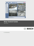
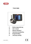

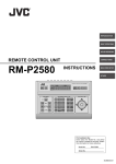
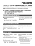
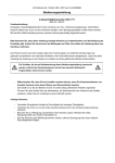


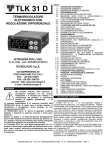
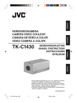
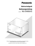
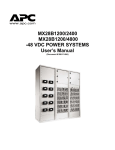
![[de] Gebrauchsanleitung ......2 [fr] Mode d`emploi ............16 [it](http://vs1.manualzilla.com/store/data/006413462_1-8d112b15fa8d80b0afb7aa9895b6c8f9-150x150.png)