1
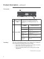
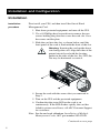
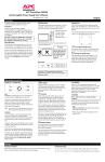
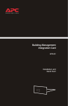
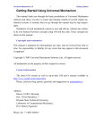
Out-of-Band Management Card AP9608 Installation Manual ® Related Documents For information on using the Out-of-Band Management Card after installation and startup, see the online User’s Guide specific to your UPS model. These manuals are in PDF (Portable Document Format). • User’s Guide: Out-of-Band Management Card for APC Silcon DP300E Series UPSs (990-6032A) • User’s Guide: Out-of-Band Management Card for APC Smart-UPS and Matrix-UPS UPSs (990-0715) • User’s Guide: Out-of-Band Management Card for APC Symmetra Power Array (990-0714) If you received a CD with your Out-of-Band Management Card, obtain the User’s Guide from that CD. If you did not receive a CD, go to http://www.apc.com/support, click User Manuals, and download the appropriate User’s Guide from the list under Out-of-Band Management Card. Contents Preliminary Information. . . . . . . . . . . . . .1 Product Description . . . . . . . . . . . . . . . . . . . . . . . . 1 Capabilities 1 Hardware requirements 1 Front panel 2 Handling 2 Initial inspection 3 Inventory 3 Please recycle 3 Installation and Configuration. . . . . . . . .4 Installation . . . . . . . . . . . . . . . . . . . . . . . . . . . . . . 4 Configuration . . . . . . . . . . . . . . . . . . . . . . . . . . . . 5 Required initial configuration 5 Accessing the cards settings 5 Configuring the required settings 7 Configuring optional settings 8 Completing the configuration 8 Powering the modem 9 Product Information . . . . . . . . . . . . . . .11 Warranty and Service Information . . . . . . . . . . . . 11 Limited warranty 11 Obtaining service 11 Warranty exclusions 11 Contacting Customer Support 12 Life-Support Policy . . . . . . . . . . . . . . . . . . . . . . . . 13 General policy 13 Examples of life-support devices 13 Specifications . . . . . . . . . . . . . . . . . . . . . . . . . . . . 14 Management port 14 Product specifications 15 Approvals 15 i Preliminary Information Product Description Capabilities The Out-of-Band Management Card (AP9608) is an American Power Conversion (APC) management product that allows you to monitor and control your APC uninterruptible power supply (UPS) by using a modem. The card provides the following features for remote management: • Remote UPS status display • Remote UPS control (for example, safe reboot during a power outage or when the server has been shut down) • Data and event logging • Operator paging in case of trouble Hardware requirements The Out-of-Band Management Card requires the following: • An APC UPS model that has a card slot: Smart-UPS®, Matrix-UPS™, Symmetra®, or Silcon™ DP300E Series. • A telephone line for paging or remote management. • A dumb terminal or a computer running a terminal emulation program (such as HyperTerminal) for configuration. • A computer with modem and terminal emulation software (such as HyperTerminal) for remote management. The modem must be able to interpret industry-standard AT commands. • One null modem cable (940-0103), supplied. You can also use the Out-of-Band Management Card with the APC Environmental Monitoring Card and the APC Web/SNMP Management Card. Continued on next page 1 Product Description continued Front panel The port used for configuration, remote management, and paging by modem. For ! Management specifications, see “Management port” on Port page 14. State of the LED " Off: The card is off. On continuously The card is on with no user logged on. Status LED Single, short flashes Handling Condition indicated A user is logged on or is logging on. Double, short flashes Lockout is in progress. Rapidly repeating flashes: The card failed its power-on self-test. The Out-of-Band Management Card is shipped in a conductive bag to dissipate damaging electrostatic charges. • Leave the card in the bag until you are ready to install it. • Handle the card by the end plate only. • Do not touch the printed circuit board (PCB) or other components. Continued on next page 2 Product Description continued Initial inspection Unpack the card, and notify the carrier and place of purchase immediately if the card was damaged during shipping. Inventory The shipment contains the Out-of-Band Management Card, a null modem cable (940-0103), and this Installation Guide. Please recycle The shipping materials for the card are recyclable. Save them for later reuse or dispose of them appropriately. 3 Installation and Configuration Installation Installation procedure First install your UPS, and then install the Out-of-Band Management Card. 1. Shut down protected equipment and turn off the UPS. 2. Use a #2 Phillips-head screwdriver to remove the two screws holding the plate that covers the card slot. Save the screws and the plate. 3. Slide the card into the slot, as shown below, until the front panel of the card is flush with the front of the slot. Warning: Inserting the card upside down can damage the card. Align the sides of the printed circuit board with the locating guides in the sides of the slot. In a UPS, the slot may be horizontal or vertical. 4. Secure the card with the screws that you removed in Step 2. 5. Turn on the UPS and the protected equipment. 6. Confirm that the status LED on the card is on continuously. If the LED flashes rapidly, the card has failed its power-on self-test; call APC Customer Support for assistance. Note: See the enclosed addendum, Installation of Multiple Management Cards, APC part number 990-0231B. Continued on next page 4 Configuration Required initial configuration You must configure the following settings locally before you can start remote operation of the card. • Communication parameters • Password protection • Time and date You can change any of these settings later through the remote connection. Accessing the cards settings To configure the initial settings for the card: 1. Connect the supplied null-modem cable (940-0103) to an available serial port on your computer and to the management port on the front panel of the card. Note: You may need an adapter (not supplied) to connect the serial port to the cable. 2. Run a terminal emulation program (such as Windows® HyperTerminal®). 3. Configure the selected serial port with the following communication parameters: 9600 bps, 8 data bits, no parity, and 1 stop bit. Note: Some terminal emulation programs require that you disconnect and reconnect for the new serial settings to take effect. 4. Make sure that the status LED is on continuously, which indicates that the card is running. Then press CTRL+P. 5. Type the password. Note: APC (uppercase) is the default password. If the password has been changed, enter the new password. Continued on next page 5 Configuration continued Introductory screens After you enter the password, the card displays a screen that identifies the UPS that is currenly connected to the card. For example: From this first screen, press any key to display the Main menu: Note: For Symmetra Power Array models, menu item 1 is named UPS Status and Diagnostics. Continued on next page 6 Configuration continued Configuring the required settings To configure the required settings: 1. Type 5 and press ENTER. 2. From the Setup menu, configure the following settings: – date and time – password (case-sensitive) – location – baud rate (Set the baud rate to 9600.) Changes are displayed when you return to the menu. 3. Press ESC to return to the Main menu. 4. Type 6 and press ENTER. 5. From the Paging Setup menu, change the default Site ID number to a unique Site ID for your site. Note: Changes to the communication settings take effect when the card issues modem commands at the end of the session. Continued on next page 7 Configuration continued Configuring optional settings You can configure optional settings of the Out-of-Band Management Card while you are logged on to perform initial configuration or later through a local or remote connection. From the Main menu: • To configure the paging capability of the card, use the Paging Setup option. • To customize UPS and modem settings, use the Call-UPS Settings option, which displays the Setup menu. • To configure event logging, use the Data/Format Logging option • To configure shutdown delay parameters, use the UPS Characteristics option. For information on these options, see the User’s Guide specific to your UPS model, available as described in “Related Documents” on the inside of this manual’s front cover. Completing the configuration 1. Disconnect the card from the dumb terminal or computer. 2. Connect the card to the modem by using a standard modem cable, not the null modem cable supplied with the card. Continued on next page 8 Configuration continued Completing the configuration, continued 3. Complete the necessary connections for your system. See the following example of typical connections: ! Server " Standard modem cable # Out-of-Band Management Card modem $ Other modem % UPS & Out-of-Band Management Card 4. Turn on the modem. See “Powering the modem” below. Powering the modem Use one of the following methods to provide electrical power to the modem that the Out-of-Band Management Card requires for remote UPS control and paging: Method Plug the modem into the protected power outlet of the UPS (the recommended method). Advantage Disadvantage The modem operates You cannot turn even under poor power on the UPS conditions or during a remotely. power failure. Plug the modem into an You can turn on the UPS remotely. unprotected electrical outlet. Paging will not work during a power failure. 9 Product Information Warranty and Service Information Limited warranty American Power Conversion (APC) warrants the Out-of-Band Management Card to be free from defects in materials and workmanship for a period of two years from the date of purchase. Its obligation under this warranty is limited to repairing or replacing, at its own sole option, any such defective products. This warranty does not apply to equipment that has been damaged by accident, negligence, or misapplication or has been altered or modified in any way. This warranty applies only to the original purchaser. Obtaining service To obtain service under warranty, you must obtain a returned material authorization (RMA) number from APC or a designated APC service center. Products must be returned to APC or to an APC service center with transportation charges prepaid and must be accompanied by a brief description of the problem and proof of date and place of purchase. See “Contacting Customer Support” on page 12 for more information, including packaging, shipping, and labeling requments for returned products. Warranty exclusions Except as provided herein, American Power Conversion makes no warranties, express or implied, including warranties of mechantability and fitness for a particular purpose. Some jurisdictions do not permit limitation or exclusion of implied warranties; therefore the aforesaid limitation(s) or exclusion(s) may not apply to the purchaser. Except as provided above, in no event will APC be liable for direct, indirect, special, incidental, or consequential damages arising out of the use of this product, even if advised of the possibility of such damage. Continued on next page 10 Warranty and Service Information continued Warranty exclusions, continued Specifically, APC is not liable for any costs, such as lost profits or revenue, loss of equipment, loss of use of equipment, loss of software, loss of data, costs of substitutes, claims by third parties, or otherwise. This warranty gives you specific legal rights, and you may also have other rights which vary according to jurisdiction. Contacting Customer Support To obtain customer support for problems with the Out-of-Band Management Card: 1. Note the serial number and date of purchase of the card, and contact Customer Support at a phone number on the back cover of this manual. A technician will try to help you solve the problem by phone. 2. If you must return the card, the technician will give you a return material authorization (RMA) number. If the warranty expired, you will be charged for repair or replacement of the card. a. Pack the card carefully. The warranty does not cover damage sustained in transit. Enclose a letter with your name, address, RMA number and daytime phone number; a copy of the sales receipt; and a check as payment. if applicable. b. Mark the RMA number clearly on the outside of the shipping carton. c. Return the card by insured, prepaid carrier to the address provided by the Customer Support technician. 11 Life-Support Policy General policy American Power Conversion (APC) does not recommend the use of any of its products in the following situations: • In life-support applications where failure or malfunction of the APC product can be reasonably expected to cause failure of the life-support device or to affect significantly its safety or effectiveness. • In direct patient care. APC will not knowingly sell its products for use in such applications unless it receives in writing assurances satisfactory to APC that (a) the risks of injury or damage have been minimized, (b) the customer assumes all such risks, and (c) the liability of American Power Conversion is adequately protected under the circumstances. Examples of life-support devices The term life-support device includes but is not limited to neonatal oxygen analyzers, nerve stimulators (whether used for anesthesia, pain relief, or other purposes), autotransfusion devices, blood pumps, defibrillators, arrhythmia detectors and alarms, pacemakers, hemodialysis systems, peritoneal dialysis systems, neonatal ventilator incubators, ventilators (for adults and infants), anesthesia ventilators, infusion pumps, and any other devices designated as “critical” by the U.S. FDA. Hospital-grade wiring devices and leakage current protection may be ordered as options on many APC UPS systems. APC does not claim that units with this modifications are certified or listed as hospital-grade by APC or any other organization. Therefore these units do not meet the requirements for use in direct patient care. 12 Specifications Management port The management port is a standard 9-pin RS-232 serial communications port with the following characteristics: • It is configured as data terminal equipment (DTE) with no handshaking • It supports bit rates of 1200, 2400, 9600, and 19,200 bits per second. • The data format is 8 data bits, 1 start bit, 1 stop bit, and no parity. • The pinout is as follows: Pin Function 1 Unused 2 Receive data unput 3 Transmit data output 4 RS-232 high 5 Ground 6 Unused 7 Request to send output 8 Clear to send input 9 Unused Continued on next page 13 Specifications continued Product specifications Type Electrical Item Operating current draw Physical Size (H × W × D) 45 mAdc (typical) 1.46" × 4.75" × 4.30" 3.7 × 12.1 × 10.9 cm 0.25 lb Weight 0.11 kg Shipping weight: Environmental Specification Operating elevation Storage elevation Operating temperature Storage temperature Operating humidity Storage humidity 0.8 lb 0.36 kg 0 to 10 000 ft MSL 0 to 3000 m MSL 0 to 50 000 ft MSL 0 to 15 000 m MSL 25 to 133° F –5 to 45° C –13 to 149° F –25 to 65° C 5 – 95% RH (noncondensing) 5 – 95% RH (non- condensing) Approvals 14 Type Approval EMC Verification EMC Verification, FCC Class A CE EN 55022 Class A EN 50081-2 including IEC 1000-4-2 IEC 1000-4-3 IEC 1000-4-4 Radio Frequency Interference Changes or modifications to this unit not expressly approved by the party responsible for compliance could void the user’s authority to operate this equipment. This equipment has been tested and found to comply with the limits for a Class A digital device, pursuant to part 15 of the FCC Rules. These limits are designed to provide reasonable protection against harmful interference when the equipment is operated in a commercial environment. This equipment generates, uses, and can radiate radio frequency energy and, if not installed and used in accordance with this user manual, may cause harmful interference to radio communications. Operation of this equipment in a residential area is likely to cause harmful interference. The user will bear sole responsibility for correcting such interference. This Class A digital apparatus complies with Canadian ICES-003. Cet appareil numérique de la classe A est conforme à la norme NMB-003 du Canada. APC Worldwide Customer Support Customer support for this or any other APC product is available at no charge in any of the following ways: • Visit the APC Web site to find answers to frequently asked questions (FAQs), to access documents in the APC knowledge base, and to submit customer support requests. – http://www.apc.com (Corporate Headquarters) Connect by links to APC Web pages for specific countries and regions, each of which provides customer support information. – http://www.apc.com/support/ Submit customer support requests. • Contact an APC Customer Support center by telephone or e-mail. – Regional centers: . – • APC Headquarters (U.S. and Canada) (1) (800) 800-4272 (toll free) Latin America (1) (401) 789-5735 (United States) [email protected] Europe, Middle East, Africa (353) (91) 702020 (Ireland) [email protected] Japan (03) 5434-2021 [email protected] Local, country-specific centers: go to http://www.apc.com/support/contact for contact information. Contact the APC representative or other distributor from whom you purchased your APC product for information on how to obtain local customer support. Entire contents copyright © 2001 American Power Conversion. All rights reserved. Reproduction in whole or in part without permission is prohibited. APC, the APC logo, Matrix-UPS, Power Array, Silcon, Smart-UPS, and Symmetra are trademarks or registered trademarks of American Power Conversion Corporation. All other trademarks, product names, and corporate names are the property of their respective owners and are used for informational purposes only. 990-0122C 8/2001