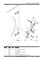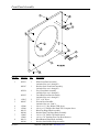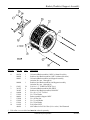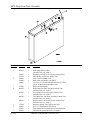
1
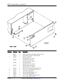
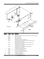
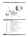
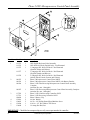
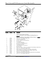
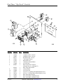
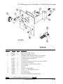
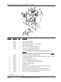
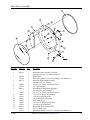
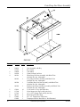
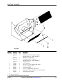
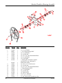
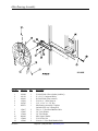
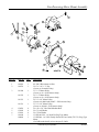
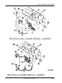
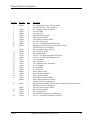
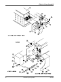
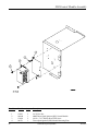
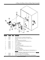
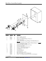
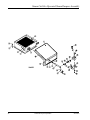
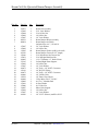
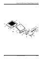
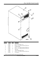
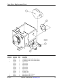
AD-15 Parts Manual
24 VAC Phase 5
For models as of July 1, 2002
American Dryer Corporation
88 Currant Road
Fall River, MA 02720-4781
Telephone: (508) 678-9000 / Fax: (508) 678-9447
E-mail: [email protected]
www.amdry.com
ADC Part No. 451101
Retain This Manual In A Safe Place For Future Reference
American Dryer Corporation products embody advanced concepts in engineering, design, and safety. If this product is
properly maintained, it will provide many years of safe, efficient, and trouble-free operation.
ONLY qualified technicians should service this equipment.
OBSERVE ALL SAFETY PRECAUTIONS displayed on the equipment or specified in the installation manual included with
the dryer.
The following “FOR YOUR SAFETY” caution must be posted near the dryer in a prominent location.
FOR YOUR SAFETY
POUR VOTRE SÉCURITÉ
Do not store or use gasoline or
other flammable vapors and
liquids in the vicinity of this or
any other appliance.
Ne pas entreposer ni utiliser d’essence
ni d’autres vapeurs ou liquides
inflammables à proximité de cet
appareil ou de tout autre appareil.
We have tried to make this manual as complete as possible and hope you will find it useful. ADC reserves the right to make
changes from time to time, without notice or obligation, in prices, specifications, colors, and material, and to change or
discontinue models.
Important
For your convenience, log the following information:
DATE OF PURCHASE ____________________________
MODEL NO.
AD-15
__________________________________________
RESELLER’S NAME _______________________________________________________________________________________
Serial Number(s)
________________________________________________________________________________________
________________________________________________________________________________________
________________________________________________________________________________________
Replacement parts can be obtained from your reseller or the ADC factory. When ordering replacement parts from the factory,
you can FAX your order to ADC at (508) 678-9447 or telephone your order directly to the ADC Parts Department at (508)
678-9000. Please specify the dryer model number and serial number in addition to the description and part number, so that
your order is processed accurately and promptly.
The illustrations on the following pages may not depict your particular dryer exactly. The illustrations are a composite of the
various dryer models. Be sure to check the descriptions of the parts thoroughly before ordering.
“IMPORTANT NOTE TO PURCHASER”
Information must be obtained from your local gas supplier on the instructions
to be followed if the user smells gas. These instructions must be posted in a
prominent location near the dryer.
Table of Contents
OPL Control Door Assembly ................................................................................................................. 3
Coin Control Door Assembly ................................................................................................................. 4
Phase 5 Coin Microprocessor Control Panel Assembly .......................................................................... 5
Phase 5 OPL Microprocessor Control Panel Assembly .......................................................................... 6
Phase 5 Coin and OPL Microprocessor Control Box Assembly .............................................................. 7
Control Vault Assembly .......................................................................................................................... 8
Dual Timer “Tap Touch” Controls ........................................................................................................... 9
Non-Microprocessor Coin Meter Control Panel Assembly ................................................................... 10
Non-Microprocessor Control Box Assembly ....................................................................................... 11
Slide Meter Case Assembly ................................................................................................................. 12
Main Door Assembly ........................................................................................................................... 13
Main Door Switch Assembly ................................................................................................................ 14
Front Panel Assembly .......................................................................................................................... 15
Basket (Tumbler)/Support Assembly .................................................................................................... 16
OPL Drop Lint Door Assembly ............................................................................................................ 17
Coin Drop Lint Door Assembly ............................................................................................................ 18
Lint Trap Assembly .............................................................................................................................. 19
Basket (Tumbler) Bearing Assembly ..................................................................................................... 20
Idler Bearing Assembly ........................................................................................................................ 21
Non-Reversing Motor Mount Assembly .......................................................................................... 22, 23
Sensor Bracket Assemblies ............................................................................................................. 24, 25
Direct Spark Ignition (DSI) Burner Assembly .................................................................................. 26, 27
Electric Oven Assembly .................................................................................................................. 28, 29
DSI Control Module Assembly ............................................................................................................ 30
Single-Phase (1ø) Motor, Electric Relay Panel Assembly ...................................................................... 31
3-Phase (3ø) Motor, Electric Relay Panel Assembly ............................................................................. 32
Slide Meter Control Box Assembly ...................................................................................................... 33
Steam Coil/Air-Operated Steam Damper Assembly ........................................................................ 34, 35
Steam Coil/Mechanical Steam Damper Assembly ............................................................................ 36, 37
Outer Top/Back Guard Assembly ........................................................................................................ 38
Coin Meter Replacement Parts ............................................................................................................ 39
Transformer Usage Listing for Gas/Steam Dryers .................................................................................. 40
Transformer Usage Listing for Electric Dryers ....................................................................................... 41
Electric Oven Component Application Chart ........................................................................................ 42
Additional Parts Available .................................................................................................................... 43
OPL Control Door Assembly
Illus. No.
1
2
3
4
5
6
7
8
9
451101-2
Part No.
Qty.
881053
870011
883388
1
1
1
883389
1
883390
1
817180
1
117604
150317
102603
102601
102502
150321
154011
4
2
1
1
1
2
2
Description
ADC Logo ONLY (with double adhesive tape)
Logo Double Tape Kit...Not Illustrated
White Control Door
(includes illus. nos. 2 and 3)
Coral Blue Control Door
(includes illus. nos. 2 and 3)
Ivory Control Door
(includes illus. nos. 2 and 3)
Stainless Steel Control Door
(includes illus. nos. 2 and 3)
Neoprene Sponge Tape (sold by the foot)
#10-16 x 3/4” TORX Plus BTN Type 1
Control Door Rod Catch
Control Door Rod Retainer Clip
Control Door Support Rod
#10-32 x 1/2” Phillips Machine Screw
#10-32 Multi-Thread U-Nut
Telephone: (508) 678-9000 / www.amdry.com
3
Coin Control Door Assembly
Illus. No.
1
2
3
4
5
6
7
8
9
10
11
4
Part No.
Qty.
160015
160104
160016
881053
870011
883416
1
1
1
1
1
1
883417
1
883418
1
883419
1
883525
117604
152014
150317
102603
102601
102502
1
6
4
2
1
1
1
Description
High Security MK-100 Lock Assembly with Key (for coin models Only)
MK-100 Key ONLY
Lock Cam ONLY
ADC Logo with Tape
Double Sided Tape Kit...Not Illustrated
White High Security Control Door Assembly with Black Trim
(includes illus. nos. 4 through 7)
Stainless Steel High Security Control Door with Black Trim
(includes illus. nos. 4 through 7)
Coral Blue High Security Door Assembly with Black Trim
(includes illus. nos. 4 through 7)
Ivory High Security Door Assembly with Black Trim
(includes illus. nos. 4 through 7)
Top Black Trim Strip with Lock Hole
Sponge Tape (sold by the foot)
1/4-20 with 3/4” Free Spin Wash Nut
#10-16 x 3/4” TORX Plus BTN Type 1
Control Door Rod Catch
Control Door Rod Retainer Clip
Control Door Support Rod
American Dryer Corporation
451101-2
Phase 5 Coin Microprocessor Control Panel Assembly
Illus. No.
1
2
3
4
5
6
7
8
9
10
11
*
Part No.
Qty.
112526
883537
1
1
883538
1
883539
883540
150309
137213
824998
153010
150005
883363
881143
137023
137021
122800
136048
1
1
1
1
1
2
2
1
1
1*
3*
1
1
Description
Coin Keyboard Label Assembly
Phase 5 Coin Control Panel Assembly
(includes illus. nos. 1, 2, 4 through 6 and 11)
Phase 5 Coin Control Panel Assembly ONLY with Battery Option
(includes illus. nos. 1, 2, 4 through 6 and 11)
Coin Control Panel ONLY
Coin Control Panel with Battery Bracket
#10-16 x 1/2” Hex Head Crimptite Screw
Phase 5 Coin Controller ONLY
Phase 5 Battery Clip
#6 Star Washer
#6-32 x 1/4” Phillips Round Head Machine Screw
Microprocessor Coin Acceptor with Optical Switch
Optic Switch ONLY
Optic Switch Connector ONLY
Microprocessor Socket ONLY
Pin/Socket Extraction Tool...Not Illustrated
1/8-Amp (Slo-Blo) Fuse ONLY
For dual coin models, double the quantity.
IMPORTANT: Check label on computer chip to verify correct part number for controller.
451101-2
Telephone: (508) 678-9000 / www.amdry.com
5
Phase 5 OPL Microprocessor Control Panel Assembly
Illus. No.
1
2
3
4
5
6
7
Part No.
Qty.
112535
112276
112275
1
1
1
112277
1
112278
1
801255
801256
801206
1
1
1
801207
1
137222
137231
824998
153010
150005
150300
136048
1
1
1
2
2
1
1
Description
OPL English Keyboard Label Assembly
OPL Stick-On Labels (English Only)...Not Illustrated
3-Language OPL Stick-On Labels...Not Illustrated
(Spanish, Italian, and Hebrew)
3-Language OPL Stick-On Labels...Not Illustrated
(English, Spanish, and Hebrew)
5-Language OPL Stick-On Labels...Not Illustrated
(Italian, Dutch, French, German, and Chinese)
Phase 5 Microprocessor Control Panel ONLY
Phase 5 Microprocessor Control Panel ONLY with Battery Bracket
Phase 5 OPL Non-Reversing Microprocessor Control Panel Assembly
Complete
(includes illus. nos. 1 through 6)
Phase 5 OPL Reversing Microprocessor Control Panel Assembly Complete
(includes illus. nos. 1 through 6)
Phase 5 OPL Non-Reversing Controller ONLY
Phase 5 OPL Reversing Controller ONLY
Phase 5 Battery Clip
#6 Star Washer
#6-32 x 1/4” Phillips Round Head Machine Screw
#10-16 x 1/2” Hex Washer TEK Screw
1/8-Amp (Slo-Blo) Fuse
IMPORTANT: Check label on computer chip to verify correct part number for controller.
6
American Dryer Corporation
451101-2
Phase 5 Coin and OPL Microprocessor Control Box Assembly
Illus. No.
*
Part No.
Qty.
1
--------
1
2
3
4
5
6
7
8
9
10
11
12
13
14
15
16
17
150300
120715
150002
151000
136057
150301
136008
122641
122706
131931
150309
137035
323583
150300
132002
150300
2
1
2
2
*
*
*
1
*
1
2
1
1
2
1
2
Description
24 VAC Control Voltage Transformer
(refer to Transformer Usage Listing for Gas/Steam Dryers on
page 40)
(refer to Transformer Usage Listing for Electric Dryers on page 41)
#10-16 x 1/2” Hex Washer TEK Screw
30-Position Terminal Block
#6-32 x 1” Phillips Round Head Screw
#6-32 Pal Nut
1/2-Amp (Slo-Blo) Fuse
#8-18 x 7/16” Self Drilling Screw
Fuse Block/Strip ONLY
15-Pin Microprocessor Connector
Sockets ONLY
Steam Valve Relay - 24 VAC (for mechanical steam damper models Only)
#10-16 x 1/2” Hex Head Crimptite Screw
Motor Capacitor (for mechanical steam damper models Only)
Capacitor Bracket (for mechanical steam damper models Only)
#10-16 x 1/2” Hex Washer TEK Screw
Transformer (for mechanical steam damper models 208 volts and higher)
#10-16 x 1/2” Hex Washer TEK Screw
As required.
451101-2
Telephone: (508) 678-9000 / www.amdry.com
7
Control Vault Assembly
Illus. No.
1
8
Qty.
802112
1
802117
802110
1
1
4
802115
160028
875061
160105*
802020
1
1
1
1
1
5
6
7
8
9
802019
125915
802018
152014
102502
102601
102603
1
1
1
4
1
1
1
2
3
*
Part No.
Description
Microprocessor Coin Vault Assembly Complete
(includes illus. nos. 1 through 6)
Microprocessor Coin Vault ONLY
Non-Microprocessor Coin Vault Assembly Complete
(includes illus. nos. 1 through 6)
Non-Microprocessor Coin Vault ONLY
Cam ONLY for 1/4 Turn Lock
1/4 Turn Lock with Key and Cam
1/4 Turn Mer-Pel Key ONLY
1/4 Turn Coin Box Assembly
(includes illus. nos. 2 through 5)
1/4 Turn Coin Box ONLY without Faceplate
High Security (Greenwald) Coin Box ONLY with Key
1/4 Turn Coin Box Faceplate ONLY
1/4-20 Free Spin Wash Nut
Control Door Support Rod
Control Door Rod Retainer Clip
Control Door Rod Catch
Specify key number when ordering.
American Dryer Corporation
451101-2
Dual Timer “Tap Touch” Controls
Illus. No.
Part No.
Qty.
1
2
3
4
5
6
7
8
124030
124025
824175
122301
131932
120730
151000
882903
1
1
1
1
3
1
6
1
9
10
11
12
13
14
15
850392
153010
152000
150207
150110
112563
124104
124105
1
2
3
2
4
1
1
1
451101-2
Description
15 Minute Timer - 24 VAC
60 Minute Timer - 24 VAC
Red Pilot Light - 24 VAC
“Tap Touch” Switch
Relay SPST 24v
30-Position Terminal Block
#6-32 Pal Nut
Dual Timer Panel Complete
(includes illus. nos. 1 through 15)
Dual Timer Panel ONLY
#6 Star Washer
#6-32 Hex Nut
#10-24 x 1/2” Phillips Pan Head Machine Screw
#8-32 x 1/4” Phillips Round Head Machine Screw
Dual Timer Panel Overlay
Pure Touch Knob with Red Pointer
Pure Touch Knob with Blue Pointer
Telephone: (508) 678-9000 / www.amdry.com
9
Non-Microprocessor Coin Meter Control Panel Assembly
Illus. No.
1
2
3
4
5
6
7
8
9
10
11
12
Part No.
Qty.
123005
122400
824172
1
1
1
824109
131932
154001
123225
125601
153010
152016
120712
150300
122602
122700
122801
1
1
2
1
1
2
2
1
1
1
7
1
Description
Red Indicator Light - 24 VAC
Rocker Heat Selector Switch
Coin Meter Control Panel Assembly Less Coin Meter
(includes illus. nos. 1 through 5 and 7 through 9)
Coin Meter Control Panel ONLY
24 VAC Relay
#10-24 Speed Nut (used on P/N 131932, 24 VAC Relay)
Green Push-To-Start Button
25¢ Coin Meter - 24 VAC (specify timing)
#6 Star Washer
Hex Nut
12-Position Terminal Block
#10-16 x 1/2” Hex Washer TEK Screw
9-Pin Connector
Pin Terminal ONLY
Pin/Socket Extraction Tool...Not Illustrated
NOTE: For Coin Meter Replacement Parts refer to page 39.
10
American Dryer Corporation
451101-2
Non-Microprocessor Control Box Assembly
Illus. No.
Part No.
Qty.
1
2
3
4
5
6
122603
122701
122801
315010
150300
150300
---------
1
9
1
1
2
2
1
7
8
9
10**
11
12
13
14
15
16
17
18
19
150309
131931
136008
136057
150301
150002
120715
151000
132002
150300
137035
323583
150300
2
1
*
*
*
2
1
2
1
2
1
1
2
Description
9-Pin Socket Connector
Socket Terminal ONLY
Pin/Socket Extraction Tool...Not Illustrated
9-Pin Connector Bracket
#10-16 x 1/2” Hex Washer TEK Screw
#10-16 x 1/2” Hex Washer TEK Screw
24 VAC Control Voltage Transformer
(refer to Transformer Usage Listing for Gas/Steam Dryers on
page 40)
(refer to Transformer Usage Listing for Electric Dryers on page 41)
#10-16 x 1/2” Hex Head Crimptite Screw
Steam Valve Relay (for mechanical steam damper models Only) - 24 VAC
Fuse Block/Strip ONLY
1/2-Amp (Slo-Blo) Fuse ONLY
#8-18 x 7/16” Phillips Pan Head TEK Screw
#6-32 x 1” Phillips Round Head Machine Screw
30-Position Terminal Block
#6-32 Pal Nut
Transformer (for mechanical steam damper 208 VAC and higher)
#10-16 x 1/2” Hex Washer TEK Screw
Motor Capacitor (for mechanical steam damper models Only)
Capacitor Bracket (for mechanical steam damper models Only)
#10-16 x 1/2” Hex Washer TEK Screw
* As required.
** Check fuse on dryer for verification.
451101-2
Telephone: (508) 678-9000 / www.amdry.com
11
Slide Meter Case Assembly
Illus. No.
1*
2
3
4
5
6
7
8
9
10
11
12
13
14
15
16
17
18
19
20
21
22
23
24
25
*
12
Part No.
Qty.
160199
160099
125908
122643
122642
152014
122631
131917
883034
883035
883036
122603
122701
883165
154203
801700
1
1
1
9
1
4
2
1
1
1
1
1
21
1
6
1
315404
-------123005
122400
-------801701
102502
102601
102603
883044
883038
883039
883040
1
1
1
1
1
1
1
1
1
1
1
1
1
Description
Key ONLY for Slide Meter Lock
Lock/Key/Cam and Hardware
Slide Meter Accumulator - 24 VAC
Mate-N-Lok Pin ONLY
9-Pin Mini-Universal Connector
1/4-20 Free Spin Wash Nut
6-Pin Connector (Mate-N-Lok)
Push-To- Start Relay - 24 VAC
White Slide Meter Case
Coral Blue Slide Meter Case
Ivory Slide Meter Case
9-Pin Connector (Mate-N-Lok)
Socket Terminal ONLY
Slide Meter Case ONLY with Door Less Lock
1/4” Drive Rivet
Slide Meter Extension ONLY with Mirror
(includes illus. nos. 14 and 15)
Stainless Steel Mirror ONLY
Typical Slide Meter Coin Chute (not available from ADC)
Red Indicator Light - 24 VAC
Rocker Heat Selector Switch
Typical Slide Meter Coin Box (not available from ADC)
Slide Meter Case Mounting Plate
Control Door Support Rod
Control Door Rod Retainer Clip
Control Door Rod Catch
Slide Meter Extension
White Slide Meter Timer Door
Coral Blue Slide Meter Timer Door
Ivory Slide Meter Timer Door
Specify key number when ordering.
American Dryer Corporation
451101-2
Main Door Assembly
Illus. No.
Part No.
Qty.
1
881150
1
2
3
102354
170731
881152
1
1
1
4
5
6
150445
153031
881151
2
1
1
7
8
9
10
11
12
13
14
15
150445
150683
152014
151010
150120
150683
152014
881210
102211
170731
2
3
3
1
1
3
3
1
1
1
451101-2
Description
Black Main Door Assembly Complete
(includes illus. nos. 1, 2, and 8 through 15)
Door Gasket
Black Glass Adhesive (10.3 oz. cartridge)...Not Illustrated
Black Top Hinge Block Assembly
(includes illus. nos. 3 and 4)
1/4-20 x 3/4” Black Cap Head Setscrew
1/4” Nylon Washer
Black Bottom Hinge Block Assembly
(includes illus. nos. 5 through 7)
1/4-20 x 3/4” Black Cap Head Setscrew
1/4-20 x 5/8” Black Carriage Bolt
1/4-20 Free Spin Wash Nut
#10-32 Black Hex Acorn Nut
Door Latch Screw
1/4-20 x 5/8” Black Carriage Bolt
1/4-20 Free Spin Wash Nut
Black Main Door Handle ONLY
20-7/16” Door Glass
Black Glass Adhesive (10.3 oz. cartridge)...Not Illustrated
Telephone: (508) 678-9000 / www.amdry.com
13
Main Door Switch Assembly
Illus. No.
1
2
3
4
5
6
7
14
Part No.
150006
152013
153010
137005
122636
881211
150301
Qty.
2
2
2
1
2
1
2
Description
#6-32 x 7/8” Phillips Pan Head
#6-32 Hex Nut
#6 Star Washer
Single-Pole Door Switch (SDS)
Flag Terminal
Main Door Switch Housing
#8-18 x 7/16” Phillips Pan Head TEK Screw
American Dryer Corporation
451101-2
Front Panel Assembly
Illus. No.
1
Part No.
Qty.
883553
1
881287
1
883554
1
883555
1
2
3
154215
881987
2
1
4
5
6
150300
150309
881152
881208
150445
150443
881151
881209
1
8
1
1
4
4
1
1
7
8
451101-2
Description
White Front Panel Assembly
(includes illus. nos. 1 through 3)
Stainless Steel Front Panel Assembly
(includes illus. nos. 1 through 3)
Ivory Front Panel Assembly
(includes illus. nos. 1 through 3)
Coral Blue Front Panel Assembly
(includes illus. nos. 1 through 3)
5/32” x 1/4” Rivet
Friction Door Latch Kit
(includes illus. nos. 2 and 3)
#10-16 x 1/2” Hex Washer TEK Screw
#10-16 x 1/2” Phillips Hex Head TEK Crimptite Screw
Black Top Hinge Block Assembly
Stainless Steel Top Hinge Block Assembly
1/4-20 x 7/8” Black Cap Head Setscrew
1/4-20 x 7/8” Stainless Steel Cap Head Setscrew
Black Bottom Hinge Block Assembly
Stainless Steel Bottom Hinge Assembly
Telephone: (508) 678-9000 / www.amdry.com
15
Basket (Tumbler)/Support Assembly
Illus. No.
1*
2
3
4
5
6
7
8
9
10
*
16
Part No.
Qty.
800700
800850
800812
1
1
1
800860
1
150313
301307
301407
100900
153001
800610
152004
153002
153001
116002
401010
24
4
4
4
4
1
4
4
4
1
1
Description
Galvanized Basket (tumbler) ONLY (without felt collar)
Stainless Steel Basket (tumbler) ONLY (without felt collar)
Galvanized Basket (tumbler) and Support Assembly
(includes illus. nos. 1 through 10)
Stainless Steel Basket (tumbler) and Support Assembly
(includes illus. nos. 1 through 10)
#10-16 x 1/2” TORX Plus BTN Type 1
Galvanized Basket (tumbler) Rib ONLY
Stainless Steel Basket (tumbler) Rib ONLY
5/16-18 x 17-1/2” Tie Rod
5/16” Flat Washer
Basket (tumbler) Support ONLY
5/16-18 Hex Nut
5/16” Lock Washer
5/16” Flat Washer
Felt Collar ONLY
#847 Adhesive for Felt Collar (5.0 oz. tube)...Not Illustrated
Felt collar is not included and must be ordered separately.
American Dryer Corporation
451101-2
OPL Drop Lint Door Assembly
Illus. No.
Part No.
Qty.
1
800150
1
2
160003
160104
160008
160009
150425
1
1
1
1
1
3
4
157000
883564
1
1
883565
1
883566
1
883141
1
117604
150419
150418
108120
7
2
1
1
5
6
7
451101-2
Description
Knob Latch Kit Assembly
(includes illus. nos. 1 and 2)
Dummy Lock ONLY (for non-coin models Only)
MK-100 Key ONLY (for dummy lock)
Lock Cam for Dummy Lock
Knob Latch Adjustable Cam ONLY
#12-24 x 3/8” Round Head Machine Screw ONLY
(screw for knob latch adjustable cam)
Drop Lint Door Spring
White Drop Lint Door Assembly without Trim
(includes illus. nos. 4 and 5)
Ivory Drop Lint Door Assembly without Trim
(includes illus. nos. 4 and 5)
Coral Blue Drop Lint Door Assembly without Trim
(includes illus. nos. 4 and 5)
Stainless Steel Lint Door Assembly without Trim
(includes illus. nos. 4 and 5)
Neoprene Sponge Tape (sold by the foot)
#6 x 1/2” Tamperproof TEK Screw
Tamperproof Screw Hand Driver...Not Illustrated
Chain for Drop Lint Door (10-1/2” length)
Telephone: (508) 678-9000 / www.amdry.com
17
Coin Drop Lint Door Assembly
Illus. No.
1
2
3
4
5
6
7
8
9
18
Part No.
Qty.
160001
160103
160008
108120
883421
1
1
1
1
1
883423
1
883424
1
883422
1
152014
117604
117603
883531
150419
150418
10
7
3
2
2
1
Description
Lock Assembly with Key
Key ONLY
Cam ONLY
Chain for Drop Lint Door
White Drop Lint Door Assembly with Black Trim
(includes illus. nos. 4 through 8)
Ivory Drop Lint Door Assembly with Black Trim
(includes illus. nos. 4 through 8)
Coral Blue Drop Lint Door Assembly with Black Trim
(includes illus. nos. 4 through 8)
Stainless Steel Drop Lint Door Assembly with Black Trim
(includes illus. nos. 4 through 8)
1/4-20 with 3/4” Free Spin Wash Nut
Noise Suppression Tape (sold by the foot)
1/8” x 9/16” Sponge Tape (sold by the foot)
Black Drop Lint Door Trim
#6 x 1/2” Tamperproof TEK Screw
Tamperproof Screw Hand Driver...Not Illustrated
American Dryer Corporation
451101-2
Lint Trap Assembly
Illus. No.
Part No.
Qty.
1
800425*
1
800426*
800400**
1
1
800403**
154200
150300
304100
800500
150419
150418
108120
1
6
3
1
2
2
1
1
2
3
4
5
6
7
Description
Choked Lint Trap Assembly Complete
(includes illus. nos. 1 and 3 through 5)
Choked Lint Trap ONLY
Lint Trap Assembly Complete
(includes illus. nos. 1 and 3 through 5)
Lint Trap ONLY
5/32” Pop Rivet
#10-16 x 1/2” Hex Washer TEK Screw
Lint Screen Holder ONLY
Lint Screen ONLY
#6 x 1/2” Tamperproof TEK Screw
Tamperproof Screw Hand Driver...Not Illustrated
Chain for Drop Lint Door
* For gas models ONLY.
** For electric models and steam models ONLY.
451101-2
Telephone: (508) 678-9000 / www.amdry.com
19
Basket (Tumbler) Bearing Assembly
Illus. No.
20
Part No.
Qty.
1
2
3
4
5
6
7
8
153002
880213
153002
152004
150501
153002
153004
801100
3
1
3
3
4
4
4
1
9
10
11
12
13
14
15
16
17
18
801105
150610
152004
150501
880201
153002
152004
101100
154301
100713
100108
1
2
2
3
1
3
3
1
2
1
1
Description
5/16” Lock Washer
1-1/4” Flange Bearing ONLY
5/16” Lock Washer
5/16-18 Hex Nut
5/16-18 x 3/4” Hex Head Machine Bolt
5/16” Lock Washer
3/8” Flat Washer
1” Bearing Box Assembly Complete
(includes illus. nos. 8 through 14)
Bearing Box ONLY
5/16-18 x 1-1/2” Allen Setscrew
5/16-18 Hex Nut
5/16-18 x 3/4” Hex Head Machine Bolt
1” Flange Bearing ONLY
5/16” Lock Washer
5/16-18 Hex Nut
18” Pulley ONLY
5/16-18 x 1” Setscrew
1/4” x 1/4” x 7/8” Key
5L-680 V-Belt (basket [tumbler] to idler)
American Dryer Corporation
451101-2
Idler Bearing Assembly
Illus. No.
Part No.
Qty.
1
2
3
4
5
6
100108
101129
100110
154301
100705
882576
1
1
1
2
1
1
7
8
9
10
11
12
150617
153005
153004
801009
152004
150509
2
2
2
1
1
2
451101-2
Description
5L-680 V-Belt (idler to basket [tumbler])
9” x 2-1/2” Compound Pulley
4L-500 V-Belt (idler to motor)
5/16-18 x 1” Allen Setscrew
3/16” x 3/16” x 1-3/8” Key
Idler Bearing Assembly Complete
(includes illus. nos. 5 through 12)
3/8-16 x 1” Hex Head Machine Bolt
3/8” Lock Washer
3/8” Flat Washer
Idler Square Washer
5/16-18 Hex Nut
5/16-18 x 3” Hex Head Machine Bolt
Telephone: (508) 678-9000 / www.amdry.com
21
Non-Reversing Motor Mount Assembly
Illus. No.
Qty.
1
2
100110
100701
1
1
3
101104
1
101132
1
101133
1
101131
1
150501
153002
153001
181049
100066
4
4
4
1
1
4
5
6
7
22
Part No.
Description
4L-500 V-Belt (motor to idler)
3/16” x 3/16” x 1” Key
(for use on 3ø models Only)
1/2” x 2” Motor Pulley
(for use on 1ø - 60 Hz motors Only)
5/8” x 2” Motor Pulley
(for use on 3ø - 60 Hz motors Only)
5/8” x 2-1/4” Motor Pulley
(for use on 100066 and 100007 - 50 Hz motors Only)
1/2” x 2-1/4” Motor Pulley
(for use on 181049 - 50 Hz motors Only)
5/16-18 x 3/4” Hex Head Machine Bolt
5/16” Lock Washer
5/16” Flat Washer
1/2 HP 100-230v 1ø 50/60 Hz Plug-Type Motor
1/2 HP 240v 1ø 50 Hz Totally Enclosed, Fan-Cooled (T.E.F.C.) Plug-Type
Motor
(for 50 Hz models mfd. prior to August 22, 2002)
American Dryer Corporation
451101-2
Non-Reversing Motor Mount Assembly (continued)
Illus. No.
Part No.
Qty.
8
122701
122801
137030
152004
153002
153001
117604
154000
800908
803930*
8
1
1
4
4
4
4
4
1
1
880819
1
803801*
1
803800*
1
153050
100604
100702
153050
152006
120200
100007*
2
1
1
2
2
1
1
9
10
11
12
13
14
15
16
17
18
19
20
21
22
*
Description
Socket Terminal ONLY
Pin/Socket Extraction Tool...Not Illustrated
8-Pin Housing Connection
5/16-18 Hex Nut
5/16” Lock Washer
5/16” Flat Washer
1/8” x 3/8” Sponge Tape (sold by the foot)
5/16-18 Tinnerman Nut
1/2 HP Motor Mount ONLY (56Z frame)
1/2 HP 115-230v 1ø 50/60 Hz Motor Mount Assembly Complete with Plug
Motor
(includes illus. nos. 2 through 7 and 13 through 20)
1/2 HP 240v 1ø 50 Hz Motor Mount Assembly Complete with Plug Motor
(includes illus. nos. 2 through 7 and 13 through 20)
1/2 HP 208/230/380/460v 3ø 60 Hz Motor Mount Assembly Complete
(includes illus. nos. 2 through 6 and 13 through 22)
1/2 HP 208/230/380/460v 3ø 50 Hz Motor Mount Assembly Complete
(includes illus. nos. 2 through 6 and 13 through 22)
1/2” Flat Washer
12-1/2” Impellor with 1/2” Bore
1/8” x 1/8” x 1-1/2” Key
1/2” Flat Washer
1/2-20 Left Hand Jam Nut
3/8” 90° Connector
1/2 HP 208/230/380/460v 3ø 50/60 Hz Motor (56Z frame)
Specify voltage when ordering.
451101-2
Telephone: (508) 678-9000 / www.amdry.com
23
Sensor Bracket Assemblies
24
American Dryer Corporation
451101-2
Sensor Bracket Assemblies
Illus. No.
Part No.
Qty.
1
880251
1
2
3
4
5
6
7
8
9
10
130103
153010
152000
121028
122701
122605
154007
150005
801425
1
2
2
2
4
1
2
2
1
11
12
13
14
15
16
17
18
19
20
21
22
23
24
305007
122604
122700
150301
150005
130111
130100
130103
130101
153010
152000
840065
121028
122701
122605
840062
1
1
4
2
5
1
1
1
1
5
5
1
4
4
1
1
25
801418
1
305007
122604
122700
122801
150301
1
1
4
1
2
26
27
28
451101-2
Description
1/4” Temperature Sensor Probe Assembly
(includes illus. nos. 1 and 5 through 8)
225° Automatic Reset Thermostat
#6 Star Washer
#6-32 Hex Nut
Insulated Terminal ONLY
Socket Terminal ONLY
4-Pin Socket Connector ONLY
1/4” Push On Fastener
#6-32 x 1/4” Round Head Machine Screw
Microprocessor Sensor Bracket Assembly Complete
(includes illus. nos. 1 through 10)
Universal Sensor Bracket ONLY
4-Pin Connector ONLY
Pin Terminal ONLY
#8-18 x 7/16” Phillips Pan Head TEK Screw
#6-32 x 1/4” Round Head Machine Screw
130° Thermostat
150° Thermostat
225° Automatic Reset Thermostat
180° Thermostat
#6 Star Washer
#6-32 Hex Nut
Sensor Jumper ONLY
Insulated Terminal ONLY
Socket Terminal ONLY
4-Pin Socket Connector ONLY
Sensor Bracket Harness Assembly
(includes illus. nos. 22 through 24)
Noncomputer Sensor Bracket Assembly Complete (includes thermostats)
(includes illus. nos. 14 through 25)
Universal Sensor Bracket ONLY
4-Pin Connector ONLY
Pin Terminal ONLY
Pin/Socket Extraction Tool...Not Illustrated
#8-18 x 7/16” Phillips Pan Head TEK Screw
Telephone: (508) 678-9000 / www.amdry.com
25
Direct Spark Ignition (DSI) Burner Assembly
26
American Dryer Corporation
451101-2
Direct Spark Ignition (DSI) Burner Assembly
Illus. No.
1
2
3
4
5
6
7
8
9
10
11
12
13
14
15
16
17
18
19
20
21
22
23
24
25
26
27
451101-2
Part No.
Qty.
141104
150108
151001
140811
140848
141230
150309
318716
128927
880960
142707
142500
142754
142600
883145
2
2
2
2
2
1
5
1
1
1
1
1
2
1
1
883146
1
850850
874051
809308
880330
150300
318700
154004
802799
122200
150303
105500
319202
154002
802800
802801
1
1
1
1
6
1
1
1
1
2
1
1
1
1
1
319704
150001
130201
151000
1
2
1
2
Description
Small Burner Tube
#8-32 x 1/2” Pan Head Machine Screw
#8-32 Pal Nut
#41 Natural Gas Burner Orifice
#54 Liquid Propane (L.P.) Burner Orifice
1/2” 2-Port Manifold
#10-16 x 1/2” Hex Head TEK Crimptite Screw
Gas Valve Bracket
1/2” 24 VAC Redundant Gas Valve (natural gas)
1/2” 24 VAC Liquid Propane (L.P.) Gas Valve
1/2” x 1-1/2” B.I. Nipple
1/2 x 90° Elbow
1/2” x 8” B.I. Nipple
1/2” Black Union
Natural Gas Burner Box Assembly Complete Less Orifice
(includes illus. nos.1 through 3 and 5 through 27)
Liquid Propane (L.P.) Burner Box Assembly Complete Less Orifice
(includes illus. nos.1 through 3 and 5 through 27)
Burner Box ONLY
Liquid Propane (L.P.) Conversion Kit
Ignitor Flame-Probe Assembly with Leads
High Voltage (HV) Wire and Connector Assembly
#10-16 x 1/2” Hex Washer TEK Screw
Pipe Bracket
Twin Speed Nut
Sail Switch Box Cover and Bracket ONLY
Sail Switch
#4 x 3/4” Pan Head Machine Screw
Sail Switch Actuator Rod
Sail Switch Damper (flat)
1/8” Push On Fastener
Sail Switch Box with Cover
Sail Switch Assembly Complete
(includes illus. nos. 15 and 17 through 23)
Hi-Limit Mounting Bracket
#6-32 x 1/2” Phillips Round Head Machine Screw
330º Manual Reset Hi-Limit
#6-32 Pal Nut
Telephone: (508) 678-9000 / www.amdry.com
27
Electric Oven Assembly
28
American Dryer Corporation
451101-2
Electric Oven Assembly
Illus. No.
Part No.
Qty.
1
803003
--------*
--------*
150300
802800
802801
1
1
2
1
1
154004
150309
802799
122200
150303
105500
319202
154002
150300
803100
320611
150207
130400
150300
154001
121010
152014
--------*
150207
120081
120080
152008
121011*
--------*
153009
320607
1
2
1
1
2
1
1
1
2
1
1
2
1
2
2
1
3
1
2
1
2
3
4
5
6
7
8
9
10
11
12
13
14
15
16
17
18
19
20
21
22
23
24
25
26
27
28
29
30
*
Description
Small Electric Oven Box ONLY
Electric Oven Assembly Complete
Electric Element
#10-16 x 1/2” Hex Washer TEK Screw
Sail Switch Box with Bracket and Cover ONLY
Sail Switch Box Assembly Complete
(includes illus. nos. 4 through 12)
Twin Speed Nut
#10-16 x 1/2” Hex Head Crimptite Screw
Sail Switch Box Cover ONLY
Sail Switch ONLY
#4 x 3/4” Pan Head “A” Machine Screw
Sail Switch Actuator Rod
Sail Switch Damper (flat)
1/8” Push On Fastener
#10-16 x 1/2” Hex Washer TEK Screw
Electric Oven Front Cover ONLY
Large Relay Box Cover ONLY
#10-24 x 1/2” Phillips Round Head Machine Screw
290º Hi-Limit
#10-16 x 1/2” Hex Washer TEK Screw
#10-24 Speed Nut
L-70 Ground Lug
1/4-20 Free Spin Wash Nut
Oven Relay
#10-24 x 1/2” Phillips Pan Machine Screw
Internal Ceramic Insulator (2 per element)
External Ceramic Insulator (2 per element)
#10-32 Hex Nut (4 per element)
Bus Bar
Oven Wiring
#10 Star Washer (2 per element)
Small Electric Oven Right Side Cover ONLY
Refer to Electric Oven Component Application Chart on page 42.
451101-2
Telephone: (508) 678-9000 / www.amdry.com
29
DSI Control Module Assembly
Illus. No.
1
2
3
4
30
Part No.
152013
801048
150301
801711
Qty.
2
1
2
1
Description
#6-32 Hex Nut
ADC Direct Spark Ignition (DSI) Control Module
#8-18 x 7/16” Phillips Head TEK Screw
Direct Spark Ignition (DSI) Module Mounting Plate
American Dryer Corporation
451101-2
Single-Phase (1ø) Motor, Electric Relay Panel Assembly
Illus. No.
Part No.
Qty.
1
2
3
132475
150299
824828
1
2
1
-
322809
150301
1
4
451101-2
Description
2-Pole Contactor - 24 VAC
#10 x 1” Hex Head TEK Screw
RC Network with Connectors
(for microprocessor models Only)
Back Electrical Box Cover...Not Illustrated
#8-18 x 7/16” Phillips Head TEK Screw...Not Illustrated
Telephone: (508) 678-9000 / www.amdry.com
31
3-Phase (3ø) Motor, Electric Relay Panel Assembly
Illus. No.
32
Part No.
Qty.
1
2
3
322812
132447
137015
1
1
1
4
5
6
7
8
9
10
11
12
150103
151001
153002
152004
120701
150008
151000
121300
---------
2
2
1
1
1
2
2
3
1
13
---
150300
322809
150301
2
1
4
Description
Back Electrical Box Component Mounting Plate
Impellor Contactor (208/230/240v, 50/60 Hz) 24 VAC
RC Filter
(for microprocessor models Only)
#8-32 x 3/4” Phillips Round Head Machine Screw
#8-32 Pal Nut
5/16” Lock Washer
5/16-18 Hex Nut
4-Position Terminal Block
#6-32 x 1-1/4” Slotted Round Head Machine Screw
#6-32 Pal Nut
Open/Closed Bushing
Step-Down Transformer
(refer to Transformer Usage Listing for Gas/Steam Dryers on
page 40)
(refer to Transformer Usage Listing for Electric Dryers on page 41)
#10-16 x 1/2” Hex Washer TEK Screw
Back Electrical Box Cover...Not Illustrated
#8-18 x 7/16” Phillips Round Head TEK Screw...Not Illustrated
American Dryer Corporation
451101-2
Slide Meter Control Box Assembly
Illus. No.
*
Part No.
Qty.
1
2
3
4
132475
150299
150300
--------
1
2
2
-
5
6
7
8
9
10
11
12
13
---
136057
150301
136008
150002
120715
151000
153002
152004
305520
322809
150301
*
*
*
2
1
2
1
1
1
1
4
Description
2-Pole Contactor - 24 VAC
#10 x 1” Hex Head Screw
#10-16 x 1/2” Hex Head Washer TEK Screw
24 VAC Transformer
(refer to Transformer Usage Listing for Gas/Steam Dryers on
page 40)
(refer to Transformer Usage Listing for Electric Dryers on page 41)
1/2-Amp (Slo-Blo) Fuse ONLY
#8-18 x 7/16” Phillips Pan Head TEK Screw
Fuse Block/Strip ONLY
#6-32 x 1” Round Head Machine Screw
30-Position Terminal Block ONLY
#6-32 Pal Nut
5/16-18 Lock Washer
5/16-18 Hex Nut
Rear Contactor Plate ONLY
Back Electrical Box Cover...Not Illustrated
#8-18 x 7/16” Phillips Pan Head TEK Screw...Not Illustrated
As required.
451101-2
Telephone: (508) 678-9000 / www.amdry.com
33
Steam Coil/Air-Operated Steam Damper Assembly
34
American Dryer Corporation
451101-2
Steam Coil/Air-Operated Steam Damper Assembly
Illus. No.
Part No.
Qty.
1
2
3
4
5
6
7
165013
153002
152004
152002
153007
820321
880834
1
6
6
4
4
2
1
8
9
10
11
12
13
14
15
16
17
18
19
20
21
22
23
24
25
26
27
28
29
30
153007
152002
115995
102350
151006
152051
100495
323365
152002
153007
100472
143110
100472
100496
143238
100498
150002
153010
152000
330987
152002
153007
100520
4
4
48
1
1
1
1
2
2
2
1
1
1
1
1
1
2
2
2
1
2
2
1
451101-2
Description
Steam Coil Assembly
5/16” Lock Washer
5/16-18 Hex Nut
1/4-20 Hex Nut
1/4” Lock Washer
Steam Damper Hinge Assembly
Steam Damper Assembly
(includes illus. nos. 7, 10, and 11)
1/4” Lock Washer
1/4-20 Hex Nut
Steam Damper Gasket (sold by the inch)
Steam Damper Foam (68-1/2” length)
5/16-24 Stainless Steel Acorn Nut
5/16-24 Right Hand Jam Nut
1-1/16” Diameter x 3” Stroke Piston
Left and Right Piston Support
1/4-20 Hex Nut
1/4” Lock Washer
1/4” Poly x 1/8” M.P.T. Connector
1/4” Poly-Flo Tubing
1/4” Poly x 1/8” M.P.T. Connector
1/8” Needle Valve
1/8” Brass Close Nipple
3-Way Micro Valve - 24 VAC
#6-32 x 1” Machine Bolt
#6 Star Washer
#6-32 Hex Nut
Micro Valve Support
1/4-20 Hex Nut
1/4” Lock Washer
1/8” N.P.T. Silencer (muffler) #N-25
Telephone: (508) 678-9000 / www.amdry.com
35
Steam Coil/Mechanical Steam Damper Assembly
36
American Dryer Corporation
451101-2
Steam Coil/Mechanical Steam Damper Assembly
Illus. No.
*
Part No.
Qty.
1
2
3
4
5
6
7
165013
153002
152004
152002
153007
820321
880835
1
6
6
4
4
2
1
8
9
10
11
12
13
14
15
16
17
18
19
20
21
22
23
24
25
26
27
28
29
30
31
115995
102350
309300
154300
153022
104052
150110
153012
312315
153022
154300
850268
150110
153012
312315
104054
100511
122120
150026
122120
150026
153012
150102
--------*
48
1
1
1
1
1
2
2
1
1
1
1
2
2
1
1
1
1
2
1
2
2
2
1
Description
Steam Coil Assembly ONLY
5/16” Lock Washer
5/16-18 Hex Nut
1/4-20 Hex Nut
1/4” Lock Washer
Steam Damper Hinge Assembly
Steam Damper Assembly
(includes illus. nos. 7, 10, and 11)
Steam Damper Gasket (sold by the inch)
Steam Damper Foam (68-1/2” - length)
Rod Bracket
1/2” x 3/32” Cotter Pin
#10 Flat Washer
Mechanical Steam Damper Actuator Rod
#8-32 x 1/4” Phillips Head Machine Screw
#8 Star Washer
Mechanical Steam Damper Motor Mount
#10 Flat Washer
1/2” x 3/32” Cotter Pin
Mechanical Steam Damper Arm
#8-32 x 1/4” Phillips Head Machine Screw
#8 Star Washer
Mechanical Steam Damper Motor Mount
Mechanical Steam Damper Motor
Mechanical Steam Damper Switch Plate
Mechanical Steam Damper Switch
#4-40 x 5/8” Phillips Pan Head Machine Screw
Mechanical Steam Damper Switch
#4-40 x 5/8” Phillips Pan Head Machine Screw
#8 Star Washer
#8-32 x 3/8” Pan Head Machine Screw
Mechanical Steam Damper Motor Cam
The mechanical steam damper motor cam is part of the mechanical steam damper motor.
451101-2
Telephone: (508) 678-9000 / www.amdry.com
37
Outer Top/Back Guard Assembly
Illus. No.
1
2
3*
4
5
6*
7
8
9
*
38
Part No.
322809
150301
330076
150301
150301
312532
330086
150301
103500
Qty.
1
4
1
7
10
1
1
13
4
Description
Back Electrical Box Cover
#8-18 x 7/16” Phillips Pan Head TEK Screw
Top Back Guard
#8-18 x 7/16” Phillips Pan Head TEK Screw
#8-18 x 7/16” Phillips Pan Head TEK Screw
Outer Top
“Plain” Bottom Back Guard
#8-18 x 7/16” Phillips Pan Head TEK Screw
Leveling Leg
There is no top back guard or outer top on steam models.
American Dryer Corporation
451101-2
Coin Meter Replacement Parts
Illus. No.
1
2
3
4
451101-2
Part No.
125541
125540
125500
125501
125502
125503
125504
125506
125507
125508
125510
125515
125516
Qty.
1
1
1
1
1
1
1
1
1
1
1
1
2
Description
1/60 RPM 24 VAC/60 Hz Meter Motor
1/30 RPM 24 VAC/50 Hz Meter Motor
2-Point Cam
3-Point Cam
4-Point Cam
5-Point Cam
6-Point Cam
8-Point Cam
9-Point Cam
10-Point Cam
12-Point Cam
Meter Switch “B” with Arm
Meter Switch “A” or “C”
Telephone: (508) 678-9000 / www.amdry.com
39
40
HEAT
VOLTAGE
WIRE
SERVICE
STEP DOWN TRANSFORMER
PART. NO.
CONTROL VOLTAGE
PART NO.
GAS/STEAM
Transformer Usage Listing for Gas/Steam Dryers
208-240
3 or 4
---------
141403
380
3
132059
141403
380
4
132059
141403
416
3
132062
141403
416
4
132062
141403
460/480
3
132053
141403
460/480
4
132053
141403
575
3
132050
141403
American Dryer Corporation
451101-2
Transformer Usage Listing for Electric Dryers
KW
VOLTAGE
PHASE
WIRE
SERVICE
STEP DOWN TRANSFORMER
PART NO.
CONTROL VOLTAGE
PART NO.
18
208
3ø
3
------
132070
18
208
1ø
2
------
132063
18
240
3ø
3
------
141403
18
416
3ø
4
------
132082
18
460/480
3ø
3
132053
141403
15
208
3ø
3 or 4
------
141403
15
208
1ø
2
------
132063
15
380
3ø
4
------
132082
15
400
3ø
4
------
132082
12
208
3ø
3
------
141403
12
240
3ø
3
------
141403
12
240
1ø
2
------
132070
12
380
3ø
4
------
132082
11
400
3ø
4
------
132082
451101-2
Telephone: (508) 678-9000 / www.amdry.com
41
Electric Oven Component Application Chart
KW
VOLTAGE
PHASE
WIRE
SERVICE
OVEN
ASSEMBLY
ELEMENT
QTY
OVEN WIRE
KW PART NO. QTY
PART NO.
BUS BAR
P/N:
121011
CAT. NO.
PART NO.
TERMINAL LUG
SIZE PART NO. QTY
OVEN RELAY
18
460/480
3ø
3 or 4
883597
6
3
120007
1
#8
882559
1
121010
2
DPA33
131352
18
416
3ø
4
826389
6
3
120007
1
#8
882558
1
121010
1
DPA33
131352
18
240
3ø
3
883542
6
3
120007
1
#8
882558
1
121010
2
DPA43
131357
18
208
3ø
3 or 4
824914
6
3
120006
1
#6
882556
1
121010
2
DPA53
131359
18
208
1ø
2
883546
6
3
120006
1
#2
883384
1
121010
2
DPA93
131358
15
380
3ø
4
826389
6
3
120007
1
#8
882558
1
121010
1
DPA33
131352
15
208
1ø
2
883547
5
3
120006
1
#4
883385
1
121010
1
DPA73
131376
12
240
3ø
3
883543
3
4
120009
1
#8
882558
1
121010
2
DPA33
131352
12
240
1ø
2
883545
4
3
120007
1
#6
883548
1
121010
1
DPA53
131359
12
208
3ø
3 or 4
883544
3
4
120008
1
#8
882558
1
121010
1
DPA33
131352
11
400
3ø
4
826401
6
2
120004
1
#8
882558
1
121010
1
DPA33
131352
42
American Dryer Corporation
451101-2
Additional Parts Available
Part No.
Description
112280
112533
112534
114001
114006
114533
120100
120200
120300
120400
120500
120600
120707
120708
120800
120902
120903
121499
121500
121503
122804
404502
404515
404516
“Lint Screen” Label
“Phase 5 Coin Program Location Summary” Label
“Phase 5 OPL Program Location Summary” Label
“Caution-Exhausted/Lint Screen” Label
“Warning-Fire Hazards” Label
“120V Electric Service” Label
3/8” Straight (BX) Connector
3/8” x 90° (BX) Connector
3/8” x 45° (BX) Connector
3/8” Red Jacket (BX) Insulator
3/8” Jiffy Clip (BX retainer clip)
3/8” Flexible Steel Electrical Conduit
Terminal Strip (2-position)
Terminal Strip (3-position)
1/4” In-Line Connector
#74B Wire Nut
Crimp-On Wire Nut
5-1/2” Harness Tie
8” Harness Tie
Harness Tie Mounting Clip
Manometer (hydro gauge) for Measuring Gas Pressure
White Brush-In-Cap Bottle Touch-Up Paint
Coral Blue Brush-In-Cap Bottle Touch-Up Paint
Ivory Brush-In-Cap Bottle Touch-Up Paint
451101-2
Telephone: (508) 678-9000 / www.amdry.com
43
ADC 451101
2 - 02/24/05-0