1
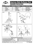
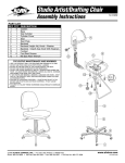
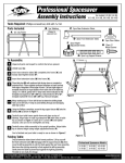
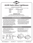
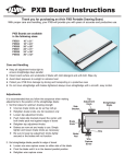
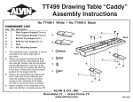
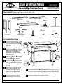
Titan Drafting Tables
B
OFFICE HEIGHT
C
Assembly Instructions
C
B
For WOB42, WOB48, WOB60,
WOB42-WA, and WOB48-WA
B
B
Tools required: Phillips screwdriver, awl, or drill with ⁄16" bit.
1
Parts Included:
A 2pcs
C
C
B 1pc
Rear Crossbar
(347⁄8" long)
C 1pc
B
Footrest Crossbar
(357⁄8" long)
D 1pc
C
Dust Cover
G 2pcs
E 2pcs
Adjustment Knobs
Tilt Adjustment Rods
H 8pcs
B
Side Frames,
B
Left & Right
F 2pcs
C
I 20pcs
J 1pc
B
Hinge Assemblies,
Left & Right
2" Allen Bolts
C
¾" Phillips Screws
C
Allen Wrench Key
C
To Assemble Base Frame
1
Unpack and inspect contents to confirm
you have all the parts listed above. Use
care to differentiate rear crossbar (B)
(34½" long) from footrest crossbar (C)
(35½" long).
2
Attach the rear crossbar (B) and
footrest crossbar (C) to one side frame
(A) using 2" Allen bolts (H). Tighten
securely. Note: Threaded barrels
preattached to leg frames must be in
rear and facing out.
3
Attach other side frame (A) to opposite
ends of crossbars in step two using 2"
Allen bolts (H). Tighten securely.
4
Place dust cover (D) over top of base
frame and attach using ¾" Phillips
screws (I). Note: Wooden strip on dust
cover should be in front of table and
facing up.
5
Attach hinge assemblies (G) to side
frames into pre-drilled holes using
¾" Phillips screws (I) as shown in
diagram. Pay close attention to correct
orientation of left and right hinges.
Tighten securely.
7
Screw adjustment knobs (E) into threaded barrels on each side frame. Set
adjustment rods so that connecting brackets are about 2" above side frames
for the time being with rods facing straight up and down and rear mounting
brackets facing out, as shown in diagram. Tighten knobs securely.
Insert tilt adjustment rods (F) into
threaded barrels on each side frame.
8
Base frame assembly is now complete. Set aside.
6
To Attach Tabletop to Base Frame
This base can be used with 42", 48", or 60" wide top.
10
Inspect tabletop carefully and choose which side you
want facing up for use. This side should be placed
face-down on a carpeted or otherwise protected floor to
avoid scratches.
11
Carefully turn base frame assembly upside down and
place on tabletop. This may require two people.
12
Position base assembly so that front hinges are 1½"
from the front edge of the tabletop, as shown in diagram.
Hinges should also be centered evenly between left and
right sides of tabletop.
13
Adjust and position rear mounting brackets so they are
19½" from the front edge of the table top and centered
evenly between left and right sides, as shown in diagram.
Brackets should sit flush on the tabletop surface with the
rods facing straight up and down.
14
Mark locations of all 12 holes with a dark pencil or
marker and then use an awl or drill with 1⁄16" bit to
make starter holes. Use care not to drill all the way
through the tabletop.
15
Attach front hinges and rear brackets to tabletop using
¾" Phillips screws (I). Tighten securely but use care not
to over tighten and strip.
19½"
19½"
1½"
©2008 Alvin & Company, Inc. • P.O. Box 188, Windsor, CT 06095-0722
Phone: 860-243-8991 • Toll-Free: 800-444-2584 • Fax: 860-242-8037 • Toll-Free Fax: 800-777-2896
Front Edge
1½"
www.alvinco.com
LIT-A8156 7/08