1
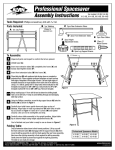
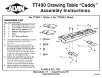
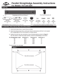
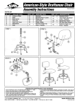
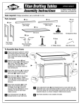
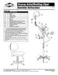
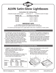
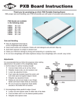
WorkMaster ™ & WorkMaster Jr.™
Assembly Instructions
Tools required: Phillips screwdriver and drill with 1⁄8" drill bit.
Parts Included:
A 2pcs
B 1pc
E 2pcs
C 1pc
Leg Frame, Left & Right
F 2pcs
Tabletop
(shipped in separate box)
D 1pc
Back Panel
Storage Shelf
Please Note: Back Panel and Storage Shelf are identical and interchangeable.
G 4pcs
H 4pcs
Rear Extension Tubes
J 1pc
I 24pcs
Cardboard
Template
Front Extension Tubes
Floor Glides
Height Adjustment Knobs
#10 x 5⁄8" Wood Screws
Tabletop Template
To Assemble: Unpack and inspect contents to confirm you have all parts listed above.
1
Fasten floor glides (G) into bottom of leg frames at each
end as shown in Figure 1.
2
Place back panel (C) on a bench or table at least 20"
high with ends hanging over the edge.
3
Hang left leg frame (A) on top of back panel as shown in
Figure 1. Make sure ends of back panel are snug against
steel leg frames and holes are aligned in steel flange
with pre-drilled holes in back panel. Attach using four 5⁄8"
screws (I) supplied. Repeat step for right leg frame.
Figure 1
Floor Glide
5
Figure 2
5
⁄8" Screws
⁄8" Screws
4
Carefully remove base assembly from table/bench and place
upright on floor.
5
Place shelf (D) with predrilled holes facing up on the bench/table with
ends hanging over edge. Lift base assembly carefully (may require two
people) and set on top of shelf. Balance with care. Align holes in steel
flange with predrilled holes in shelf and insert 5⁄8" screws (I) making
sure ends of shelf are snug against steel frames (see Figure 2). Tighten
securely, but use care not to overtighten and strip.
6
Remove base assembly carefully from table/bench and place
upright on floor.
7
Insert two rear extension tubes (E) at rear of frame
as shown in Figure 3. Curved black caps on tubes
should be set into frame so inclines face front and
back of frame. Carefully insert two front extension
tubes (F) with attached brackets facing out. All
four extension legs should be at their lowest
position and locked with four height adjustment
knobs (H). Set base aside.
Figure 3
Front extension tube
Rear extension tube
Adjustment knob
Figure 4
8
TIP
9
5
Place tabletop (B) with preferred side facing down on carpeted or protected floor.
Place supplied cardboard template on board surface with edge of template at front
edge of board. Left and right edges of template should be an equal distance from
each side of the tabletop. Using a 1⁄8" drill bit, gently drill ¼" deep holes where
marked on the template. Remove template.
Wrap masking tape ¼" from drill bit end to determine drilling depth. Take care to
drill only ¼" deep to avoid drilling through and destroying tabletop surface.
Carefully turn table assembly upside down and place on top of tabletop. Align holes
in front leg extension brackets (F) with holes in tabletop (see Figure 4). Fasten all
5
⁄8" screws (I) and tighten securely. Use care not to overtighten and strip.
⁄8" Screws
Figure 5
Carefully return table assembly to the upright position. Adjust
10 tabletop
to desired height using height adjustment knobs (H).
You’re finished and your table is ready to use (see Figure 5).
WORKMASTER
MODELS:
WORKMASTER JR.
MODELS:
WM48-3-XB
WM48-4-XB
WM60-3-XB
WM60-4-XB
WM72-3-XB
WM72-4-XB
WMJ-3-XB
WMJ-4-XB
WMJ48-3-XB
WMJ48-4-XB
WMJ-3-WBR
WMJ-4-WBR
WMJ-3-XBR
WMJ-4-XBR
©2007 ALVIN & COMPANY, INC. • P.O. Box 188, Windsor, CT 06095-0722
Phone: 860-243-8991 • Toll-Free: 800-444-2584 • Fax: 860-242-8037 • Toll-Free Fax: 800-777-2896
www.alvinco.com
LIT-A7010 5/07