1
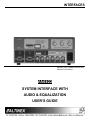
INTERFACES
MANUAL PART NUMBER: 400-0103-001
PRODUCT REVISION: 2
VA6822
SYSTEM INTERFACE WITH
AUDIO & EQUALIZATION
USER’S GUIDE
INTERFACES
TABLE OF CONTENTS
Page
PRECAUTIONS / SAFETY WARNINGS ............... 2
GENERAL.......................................................... 2
RACK MOUNT SAFETY GUIDELINES.............. 2
INSTALLATION ................................................. 2
CLEANING ........................................................ 2
FCC / CE NOTICE ............................................. 2
ABOUT YOUR INTERFACE ................................. 3
TECHNICAL SPECIFICATIONS ........................... 3
VA6822 DESCRIPTION ........................................ 4
COMPUTER VIDEO INPUT............................... 4
LOCAL MONITOR OUTPUT.............................. 5
MAIN (RGBS/RGBHV) OUTPUTS THROUGH
6 BNC CONNECTORS ...................................... 5
HORIZONTAL POSITION ADJUSTMENT ......... 5
HORIZONTAL DELAY REMOVAL ..................... 6
MOUNTING CAPABILITY.................................. 6
POWER REQUIREMENTS................................ 6
BANDWIDTH ..................................................... 6
EQUALIZATION................................................. 6
APPLICATION DIAGRAM ..................................... 8
INSTALLING YOUR INTERFACE ......................... 9
OPERATION....................................................... 10
SERRATION PULSE SWITCH ........................ 10
H&V OUT SWITCH.......................................... 10
I.D. BIT SWITCH ............................................. 10
SYNC ON GREEN OUTPUT SWITCH ............ 10
TERMINATION SWITCH ................................. 10
EQUALIZATION............................................... 10
AUDIO ............................................................. 10
ACCESSORIES .................................................. 11
FAQ (FREQUENTLY ASKED QUESTIONS)....... 12
TROUBLESHOOTING GUIDE ............................ 12
ALTINEX POLICY ............................................... 13
LIMITED WARRANTY ..................................... 13
RETURN POLICY............................................ 13
CONTACT INFORMATION.............................. 13
1
1
INTERFACES
1
•
Please read this manual carefully before using your
VA6822 Interface. Keep this manual handy for
future reference. These safety instructions are to
ensure the long life of your VA6822 and to prevent
fire and shock hazard. Please read them carefully
and heed all warnings.
Do not place heavy objects on top of the
VA6822. If the VA6822 is to be mounted to a
table or wall, use only ALTINEX-made
mounting
accessories
like
brackets
(DA1293FC or DA1294FC) and cables for
optimum setup.
•
To turn off the main power, be sure to remove
the cord from the power outlet. The power
outlet socket should be installed as near to the
equipment as possible, and should be easily
accessible.
•
Do not pull the power cord or any cable that is
attached to the VA6822 Interface.
•
If the VA6822 Interface is not used for an
extended period, disconnect the power cord
from the power outlet.
PRECAUTIONS / SAFETY WARNINGS
1.1 GENERAL
•
•
Unauthorized personnel shall not open the unit
since there are high-voltage components
inside.
Qualified ALTINEX service personnel, or their
authorized representatives must perform all
service.
1.2. SAFETY GUIDELINES FOR THE RACKMOUNTING OF THE VA6822
•
Maximum operating ambient temperature is 35
(degrees C).
•
Never restrict the airflow through the devices’
fan or vents.
•
When installing equipment into a rack,
distribute the units evenly. Otherwise,
hazardous conditions may be created by an
uneven weight distribution.
1.4 CLEANING
•
1.5 FCC / CE NOTICE
•
This device complies with part 15 of the FCC
Rules. Operation is subject to the following two
conditions: (1) This device may not cause
harmful interference, and (2) this device must
accept any interference received, including
interference that may cause undesired
operation.
•
This equipment has been tested and found to
comply with the limits for a Class A digital
device, pursuant to Part 15 of the FCC Rules.
These limits are designed to provide
reasonable
protection
against
harmful
interference when the equipment is operated
in a commercial environment. This equipment
generates, uses, and can radiate radio
frequency energy and, if not installed and
used in accordance with the instruction
manual, may cause harmful interference to
radio communications. Operation of this
equipment in a residential area is likely to
cause harmful interference in which case the
• Connect the unit to a properly rated supply
circuit.
•
Reliable Earthing (Grounding) of RackMounted Equipment should be maintained.
1.3 INSTALLATION
•
For best results, place the VA6822 Interface
on a flat, level surface in a dry area away from
dust and moisture.
•
To prevent fire or shock, do not expose this
unit to rain or moisture. Do not place the
VA6822 Interface in direct sunlight, near
heaters or heat radiating appliances, or near
any liquid. Exposure to direct sunlight, smoke,
or steam can harm internal components.
•
Handle the VA6822 Interface carefully.
Dropping or jarring can damage internal
components.
Unplug the VA6822 power cord before
cleaning. Clean surfaces with a dry cloth.
Never use strong detergents or solvents such
as alcohol or thinner. Do not use a wet cloth or
water to clean the unit.
2
2
INTERFACES
user will be required to correct the interference
at his own expense.
•
FEATURES/
DESCRIPTION
GENERAL
No. of Inputs
Input Connector
Any changes or modifications to the unit not
expressly approved by ALTINEX, Inc. could
void the user’s authority to operate the
equipment.
ABOUT YOUR INTERFACE
VIDEO
1
1
3.5 mm stereo
15-pin HD
jack
Female
1 Main + 1
1 Main + 1 Local
No. of Outputs
Local Monitor
Monitor
Local Output
3.5 mm stereo
15-pin HD
Connector
jack
Female
Main Output
5-position
5 BNC Female
Connector
Terminal Block
Stereo or mono
VGA/SVGA/
Compatibility
unbalanced
XGA/UXGA
Signal
audio
MAC/SUN/SGI
and other analog
computer video
sources with
RGBS or
RGBHV signal
types & RGsB
(pass-through)
Table 1. VA6822General
2
There are a several varieties of computers and
computer video cards on the market today. There
are also numerous monitors and large screen data
projectors. When displaying a computer image on
a large screen projector or on a large screen
monitor, it often becomes clear that some
computers are not always compatible with certain
display devices. The VA6822 is a computer video
interface designed to resolve this incompatibility.
The VA6822 is a system interface, which can be
table mounted or rack mounted.
The VA6822 is single input computer video
interface with audio. It is designed to interface up
to one VGA/SVGA/XGA/UXGA/MAC SUN or SGI
computer video source to two scan-rate compatible
presentation monitors or data projectors.
MECHANICAL
SPECIFICATIONS
Depth (inches)
It is important to understand the general
capabilities of interfaces. Interfaces do not change
the scan-rate or the resolution of the video signal.
An interface simply converts a computer video
signal to a pre-selected analog format.
Value
6.00 in. (153mm)
8.5 in. (216mm)
Width (inches)
½ rack wide
Height (inches)
1.76 in (44.7mm) 1U
Weight (pounds)
1.0 lb. (0.45kg)
Ship Weight (pounds)
1.6 lb. (0.73kg)
Material
Aluminum
Finish
Paint, ALTINEX Gray
Top Panel
Lexan Overlay
T° Operating
10°C-35°C
T° Maximum
50°C
Humidity
90% non-condensing
MTBF (calculations)
40,000 hrs
Table 2. VA6822 Mechanical Specifications
The VA6822 is a state-of-the art piece of
equipment with an exceptional combination of
compact size, advanced features, and very
competitive pricing.
TECHNICAL SPECIFICATIONS
AUDIO
3
3
3
INTERFACES
ELECTRICAL
AUDIO
SPECIFICATIONS
Input Signals
Level
0.1 to 4.8V
p-p
Impedance
Output Signals
Type
Level
10k Ohms
Balanced on
Main;
Unbalanced
on Local
0.1 to 4.8V
p-p
Position Range
VIDEO
Panel, 10%
through remote Hposition connector
Power
Power Input
100-240V AC, 50/60Hz, 0.4A
Power
10 watts max.
Consumption
Table 3. VA6822 Electrical Specifications
0.3 to 1.2V p-p for
RGB video signal
TTL (+/-) for H, V, or
C sync signal. 0.3V for Sync on
Green
75 Ohms (±1%) for
video signal; 10k
Ohms for sync
signals
VA6822 DESCRIPTION
4
The VA6822 has two key functions. First, it
amplifies (buffers) the input video and audio signal
so that it is strong enough to travel long distances
up to 350ft through high quality cables to a distant
display and audio receiver. The second function of
the VA6822 is to process the incoming sync signal
and convert it to a format that is accepted by a
projector. The computer and projector should be
scan-rate compatible.
RGsB /RGBS/
RGBHV
(pass-through)
0.3 to 1.2V p-p for
RGB video signal
TTL (+/-) for H, V, or
C sync signal. 0.3V for Sync on
Green
Impedance
620 Ohms for 75 Ohms for video
balanced; 50 signal; 22 Ohms for
Ohms for
sync signal
unbalanced
on Local
Monitor
Gain
0 dB
1.05
Equalization of
User adjustable 16Main Output
___
position through
front panel
Equalization
25ft increment, up to
Range
___
300ft with super
high resolution
cable
Target Frequency
___
Mid to high up to
350MHz
Frequency Compatibility
Frequency
20Hz to 20kHz Horizontal sync –
15 to 130kHz;
Vertical sync – 25
to 180Hz
Bandwidth
20kHz
Minimum 350MHz
minimum
for -3dB loss
Horizontal
20% through dial
___
Adjustment
on the Front
4.1 COMPUTER VIDEO INPUT (VGACOMPATIBLE 15-PIN HD CONNECTOR)
The 15-pin HD connector input allows the
connection of a computer to the system interface
using ALTINEX-made input cables which are
available for a variety of popular computers and
graphics cards on the market such as VGA, MAC,
SUN, and SGI. The input of the VA6822 is
compatible with VESA standard-VGA/XGA, which
is shown below.
PIN
No.
1
2
3
4
5
6
7
8
9
10
11
PIN
No.
12
4
4
INPUT SIGNALS ON 15 PIN-HD FEMALE
CONNECTOR
Red Video
Green Video
Blue Video
ID Bit 2
SCL/SDA ID Bit Reference/ Return
Ground
Ground
Ground
Vesa +5V
Sync Return
ID Bit 0
INPUT SIGNALS ON 15 PIN-HD FEMALE
CONNECTOR
SDA – DDC Data
INTERFACES
offers the main output with 5-BNC connectors. By
connecting to the appropriate connectors of the
VA6822, it can provide RGSB, RGBHV, or RGBS
output signals.
Horizontal Sync
13
Vertical Sync
14
SCL – DDC Clock
15
Table 4. VA6822 Input pin-outs
With these connectors the VA6822 can be
connected to compatible data projectors using
3 coax, 4 coax, or 5 coax cables.
4.2 LOCAL MONITOR OUTPUT (15-PIN HD
CONNECTOR)
The 15-Pin HD connector output is used to
connect the local monitor to the interface.
CONNECTOR
MAIN DUAL OUTPUT (6-BNC
FEMALE)
Red Video
Red
Green Video
Green
Blue Video
Blue
Sync/ Horizontal Sync
HSYNC
Vertical Sync
VSYNC
Composite Sync
CSYNC
Table 6. VA6822 Main Output pin-outs
This is a fully buffered output, eliminating
reflections often caused by “Y” type monitor
breakout cables. This output does not have to be
terminated if unused. The Local Monitor output is
buffered so that it can drive a distance up to 25ft
with high-resolution coaxial cable. The output is
VESA compatible for VGA through UXGA signals,
but can also be used to transmit signals to other
types of local monitors using designated ALTINEX
adapter cables such as MAC, SUN, SGI, or RGB.
PIN
No.
4.4 HORIZONTAL POSITION ADJUSTMENT
Most monitors and projectors have the ability to
adjust the horizontal position of the image, but in
some instances it is helpful to be able to control
this feature at the interface. This control is
especially useful when multiple computers are
switched to a single display and the horizontal
positions from each computer are slightly
different.
LOCAL MONITOR OUTPUT SIGNALS ON
15-PIN HD FEMALE CONNECTOR
Red Video
Green Video
Blue Video
ID Bit 2
SCL/SDA ID Bit Reference/ Return
Ground
Ground
Ground
Composite SYNC (used for MAC/ SUN /
9
SGI)
10 Sync Return
11 ID Bit 0
12 SDA – DDC Data
13 Horizontal Sync
14 Vertical Sync
15 SCL – DDC Clock
Table 5. Local Monitor Output pin-outs
1
2
3
4
5
6
7
8
With the VA6822’s horizontal position control dial
in the OFF (locked) position, first the image
should be adjusted using the control on the
monitor or projector. Then adjust the image with
the VA6822’s horizontal position control dial
located on the front panel.
To disable the adjustment of the horizontal
position of the image, turn the horizontal position
dial fully to the right until a “clicking” sound is
heard.
The VA6822’s horizontal position of the image can
also be adjusted remotely using an available
optional accessory that is inserted into a 3.5mm
jack labeled as “Remote H-position”. To enable
adjustment of the image’s position, first the Hposition dial located on the front panel must be in
a locked position. Now using the knob on the
optional accessory, the image can be shifted.
4.3 MAIN OUTPUT THROUGH 5 BNC
CONNECTORS
BNC connectors offer a reliable connection for
high-resolution video signals, and they facilitate
easy cable maintenance in the field. The VA6822
5
5
INTERFACES
Please note that using a longer cable or a nonALTINEX cable for remote horizontal position
could affect the stability of the picture by creating
unwanted jitter.
The VA6822 has a high bandwidth of 350 MHz
allowing high-resolution signals to pass through
the unit without attenuation for a long run. For
cable runs longer than 100ft, the signal attenuates
at medium and/or high frequency. To correct this
cable attenuation problem, the VA6822 is
equipped
with
a
feature
called
Equalization/Peaking on the front panel for each
video signal: red, green, and blue. These
channels can be equalized individually. Starting
from step one on the dial, equalization can be
increased to step E for longer cable lengths in
increments of 25ft with a slotted screw driver.
Before increasing to the next level, check the
sharpness of the picture on the display. If the
picture is sharp enough, do not increase it to the
next level.
4.5 MOUNTING CAPABILITY
The VA6822 can be easily mounted into an
equipment rack. Four mounting holes are provided
on each side of the unit. To mount a single unit,
use ALTINEX 19”-1U Rack Mount Ears (part #
DA1294FC). To mount two units in tandem, use
an ALTINEX 19”-1U Rack Mount Shelf (part #
DA1293FC). For under the table mounts, optional
brackets like the TM1271, TM1272, TM1273, or
TM1274 can be used.
4.6 POWER REQUIREMENTS
With a good quality of output cables and a strong
input signal, the VA6822 can drive signals up to
300ft with minimal loss of the signal quality.
The VA6822 may be used anywhere in the world
where the voltage is from 100 to 240 volts AC at
50/60 Hz. For the safety of the user and for
protection of the unit, make sure that the input
voltage of the VA6822 is in the range of 100 to
240VAC. The unit is auto-switchable so that no
user adjustments are necessary when switching
from 120 to 220VAC for different countries. The
LED located on the front and back panel should
light RED or GREEN when valid power input is
transmitted to the VA6822.
4.7 BANDWIDTH
The typical bandwidth of the VA6822 is 425 MHz.
The minimum bandwidth is 350 MHz. This
exceptionally high bandwidth allows passing of the
third harmonics of the video signal, thus
maintaining the highest quality of the video signal.
The VA6822 can easily pass signals from VGA
through UXGA. The signal quality at the display/
target will depend upon the type and quality of
cable used.
4.8 EQUALIZATION
6
6
INTERFACES
DESCRIPTION OF VA6822
4
7
7
INTERFACES
APPLICATION DIAGRAM
5
8
8
INTERFACES
INSTALLING YOUR INTERFACE
to 240 VAC 50/60Hz. It is not necessary
to change any voltage selection settings
on the VA6822. The LED on the front and
back panel of the VA6822 will light
GREEN if the appropriate input signal is
present and will remain RED if a valid
input is not detected.
6
Step 1. Please attach the VA6822 Interface on
the rack using the provided rack mount
hardware or on/under furniture using the
optional TM Series ALTINEX brackets.
Step 2. Connect one end of the input cable to the
video output connector of the source
computer and the other end to the
computer input port of the VA6822.
Step 9. It is recommended that you move the
VA6822’s horizontal position dial to the far
right facing the front until it clicks. This will
disable the movement of the horizontal
position of the image. The horizontal
position of the image should first be
adjusted using the control provided by the
monitor or projector. If further adjustments
are still required, then image can be
adjusted using the horizontal position
control dial located on the front of the
VA6822.
Step 3. Connect an audio input cable’s 3.5mm
plug to the audio output of a source
computer and the other end to the audio
input connector of the VA6822. If needed,
use a similar cable to connect the audio
output of the VA6822 to a speaker or
audio equipment.
Step 4. Connect the local monitor output
connector of the VA6822 to a local
monitor or display using the appropriate
ALTINEX Local Monitor cables. It is not
necessary to terminate this output with a
termination plug if a local monitor is not
being used.
Step 10. Adjust the equalization channels for the
Red, Green, and Blue channels to get the
best possible image on the display. It is
recommended to increase equalization on
all three channels simultaneously until the
picture is perfect.
Step 5. Connect one end of a coaxial cable to the
main output of the VA6822 and the other
end to the RGBHV/RGBS input on the
projector or monitor. Usually either a 4
BNC
or
5
BNC
coaxial
cable
is used, depending on whether the display
devices require composite sync (RGBS)
or separate horizontal and vertical sync
(RGBHV) signals.
Step 6. Connect the main audio output from the
VA6822 through the provided 5-position
terminal block to the input of a sound
system amplifier.
Step 7. Make sure that the dip- switches are set
as described in section 7.
Step 8. Using the provided power cable for your
country of usage, connect the power input
IEC connector to the AC wall outlet. The
power supply used in the VA6822 is
universal so it can accept from 100 VAC
9
9
INTERFACES
OPERATION
7.4 SYNC ON GREEN SWITCH
7
Often systems that use large matrix switchers are
designed to switch signals in RGsB format. This is
done to reduce the cost of the switcher and cable.
In these types of systems, the ability of the
VA6822 to output Sync on Green can be very
helpful. It is important to note that the VA6822 will
not separate the Sync signal from the Green video
signal if the input signal is RGsB. When the Sync
on Green dip-switch is in the ON position; the
VA6822 will combine a composite sync of -0.3V
amplitude to the green video signal to provide
RGsB output if the input signal is in RGBS or
RGBHV format from the source. When the Sync
on Green dip-switch is in the OFF position, the
unit will provide all RGsB, RGBS or RGBHV
signals at the output connectors in the same
format as the input.
In most cases no adjustments are necessary to
obtain a good quality picture on the display;
however, dip-switches located on the front panel
should be set for certain types of input and output
signals. The factory default settings are shown
below in Table 7. The VA6822 will operate
successfully as long as cables are attached
properly and all technical specifications of input
and operating environment are maintained.
DIP SWITCH
OFF
HV Output
HV Align
X
Option
X
Sync on Green
X
ID Bit/ Pin 4
Not Used
X
Table 7. Dip-switch default settings
ON
X
X
7.5 ID BIT SWITCH
7.1 H&V OUTPUT SWITCH
Some computers on the market, especially laptop
computers, require the presence of a local monitor
to correctly output video. The ID Bit switch, when
turned ON, will connect Pin 4 to ground. This
enables the interface to imitate a local monitor if
one is not being used in the system. When the ID
Bit switch is in the OFF position, the ID Bit of pin 4
is passed through to the local monitor output.
This dip-switch controls the type of sync signal
that is present on the HSYNC connector. If the
H&V output dip-switch is in the OFF position, then
the composite sync signal is present on the
HSYNC connector when the input in RGBS or
RGBHV format. If the H&V output dip-switch is in
the ON position, then the horizontal sync signal is
present on the HSYNC connector when the input
is in RGBS or RGBHV format.
7.6 NOT USED
This dip-switch is not used for any settings at this
time.
7.2 H&V ALIGN SWITCH
By default the H & V ALIGN dip-switch is in the
OFF position, so Horizontal and Vertical SYNC
signals are independent. By turning this dip-switch
to the ON position, the pulse of both HSYNC &
VSYNC signals start at the same point for the
benefits of some LCD projectors.
7.3 OPTION SWITCH
By default, this dip-switch is in the OFF position.
By putting it in the ON position, the duration of
Vertical SYNC of the signal is reduced to 10ms.
This allows stability of the signal on a long run
cable. It is not recommended to use the H&V
ALIGN feature when the Option dip-switch is ON.
10
10
INTERFACES
ACCESSORIES
MS8123CA/
MS8153CA/
MS8163CA
MS8124CA/
MS8154CA/
MS8164CA
RGB
MS8129CA
AUDIO CABLE
8
Model No.
Description
RACK MOUNT ACCESSORIES
Rack/Wall Shelf fits two VA6822
DA1293SX
units side by side
Rack/Wall mount ears for single
DA1294SX
VA6822
TABLE MOUNT BRACKETS
1U High, ½ Rack-Wide
TM1271
1U High, ½ Rack-Wide with 15-pin
TM1272
HD connector plate
1U High, ½ Rack-Wide with snapTM1273
in connectors
1U High, ½ Rack-Wide with snapTM1274
in POWER connectors
POWER CORD
Power Supply for US
PS5301US
(requires Adapter Cable)
Power Supply for UK (BS1363
PS5302UK
Compliant) with 5 Amp fuse
Power Supply for Australia
PS5303AU
Power Supply for Germany, 220V
PS5304GR
INPUT CABLES
VGA w/ AUDIO
VGA audio input cable
CB901-A1
VGA audio input cable
CB901-A2
VGA audio input cable
CB901-A3
VGA
MS8125CA/
VGA local monitor output cable
MS8155CA/
MS8165CA
MS8126CA/
VGA input cable
MS8156CA/
MS8166CA
MAC
MS8121CA/
MAC local monitor output cable
MS8151CA/
MS8161CA
MS8122CA/
MAC input cable
MS8152CA/
MS8162CA
MS8131CA
MS8130CA
CB102SMM0006SMM
OUTPUT
CABLES
CB4203MR
CB4206MR
CB4212MR
CB4225MR
CB4250MR
CB4275MR
CB42100MR
CB42150MR
TBD
SUN/SGI
11
11
SUN local monitor output cable
SUN input cable
5 coax. (BNC) cable
SUN SPARC Local Monitor output
cable
SUN SPARC Input Cable
Audio (3.5mm) cable
5 BNC TO 5 BNC COAXIAL
CABLE
3 feet, 5 BNC to 5 BNC coaxial
cable
6 feet, 5 BNC to 5 BNC coaxial
cable
12 feet, 5 BNC to 5 BNC coaxial
cable
25 feet, 5 BNC to 5 BNC coaxial
cable
50 feet, 5 BNC to 5 BNC coaxial
cable
75 feet, 5 BNC to 5 BNC coaxial
cable
100 feet, 5 BNC to 5 BNC coaxial
cable
150 feet, 5 BNC to 5 BNC coaxial
cable
Remote Horizontal position SNAPIN connector
INTERFACES
FREQUENTLY ASKED QUESTIONS
No:
1
2
3
4
Question
When and
why do I
need to
use the
horizontal
position
dial?
What dipswitch do I
set to
receive
composite
SYNC
output?
When and
why would
I use the
Sync on
Green dipswitch,
although
the unit
does not
separate
Sync from
Green?
When do I
use the
H&V Out
dip-switch?
9
TROUBLESHOOTING GUIDE
Answer
The horizontal position control
dial enables or disables the
control of the horizontal
position of the image. First
adjust the horizontal position
using the monitor or projector
control, and then use the
horizontal position control of
the VA6822, if needed.
The first option is to take the
output from RED, GREEN,
BLUE & CSYNC connectors
regardless of the dip-switch
settings. The second option is
to turn OFF the H&V Output
dip-switch and take the output
from RED, GREEN, BLUE,
and HSYNC connectors.
The VA6822 does not
separate the sync signal from
green, but if the desired output
is in RGsB format when the
input signal is RGBS or
RGBHV, then turn the sync on
green dip switch to the ON
position. The VA6822
combines Sync on Green if
this switch is in the ON
position.
If the desired output is in
RGBHV format, then turn ON
the H&V Out dip-switch. If the
H&V Out dip-switch is OFF,
then composite sync may be
present on the HSYNC
connector.
12
12
10
1.
The power LED should turn RED when the
correct voltage is applied to the Interface. It
should turn GREEN when both power and a
valid input signal is applied. If the power LED
is absent when the unit is turned ON, return
the VA6822 to the factory for repair.
2.
Make sure the cables have the correct pin-out
and the connection and quality of the cables
is good.
3.
Make sure that the source and display are
scan-rate compatible. The projector should
support an appropriate signal format (RGsB,
RGBS or RGBHV). Connect the projector
directly to a computer with a shorter cable to
verify the compatibility of display and source.
4.
If the desired output is in RGBS format, then
the H&V Output dip-switch is in the OFF
position and the Composite SYNC signal is
taken from the HSYNC or CSYNC connector.
If the display needs an RGBHV signal, then
the H&V Output dip-switch should be in the
ON position and the sync signal is taken from
the HSYNC and VSYNC connectors.
5.
If the desired output is RGsB, then the SYNC
ON GREEN dip-switch should be ON.
6.
If the image bends on top of the screen and
RGBHV output is used, then turn on the H&V
Output dip-switch.
7.
Please make sure that the amplitude level of
the input signal is as follows:
a) RED, GREEN, and BLUE channels are
less than 1.2Volts
b) HSYNC & VSYNC are less than 5.0 volts
8.
Please use only an ALTINEX supplied power
cord suitable to the country of usage for
proper operation of the VA6822.
9.
If problems show up on the display after
continuous usage at higher voltage, higher
temperature, higher humidity, or at other
extreme environmental conditions, please
correct those extreme conditions.
INTERFACES
ALTINEX POLICY
returned without an RMA number may experience
a delay in service.
11
11.1 LIMITED WARRANTY
If your product is out of warranty and needs
service, contact the ALTINEX Sales Department
for an RMA (Return Material Authorization).
Products returned without an RMA number may
experience a delay in service. The service
charges will be quoted to you before the actual
repairs are done.
ALTINEX warrants that its products and cables
are free from defects in materials under normal
use and service. This warranty is limited to
repairing at company’s factory any part or parts of
the product, which upon company’s examination
shall disclose to be, thus defective. Products
considered defective should be returned to
company with transportation charges pre-paid
within 2 years (90 days for cables) from date of
shipment to the purchaser. The warranty is
expressly instead of all other warranties
expressed or implied. ALTINEX neither assumes
nor authorizes any other person to assume for it
any other liability in connection with the sale of the
products. This warranty shall not apply to any
product that shall have been repaired or altered
outside of company’s factory in any way so as, in
its judgment, to affect its stability or reliability, or
that has been subject to misuse, negligence, or
accident.
11.3 CONTACT INFORMATION
Sales Department
Phone: 714-990-2300
Fax: 714-990-3303
11.2 RETURN POLICY
It is very important to ALTINEX that you receive
the products that you have ordered and that this
product meets your expectations. In the unlikely
event, that an ALTINEX product needs to be
returned please follow the policy below:
ALTINEX will accept product returns for a period
of 30 days from authorized ALTINEX dealers.
Products must be returned in an unopened
package.
If a product has been opened, the restocking fees
will apply. For the restocking fee amount, please
contact an ALTINEX Sales Representative.
If the product is in your possession for more than
30 days, the restocking fees will apply.
ALTINEX will not accept any returns on cables or
custom products.
If your product is in warranty and needs service,
contact the ALTINEX Sales Department for an
RMA (Return Material Authorization). Products
13
13