1
SPECIAL APPLICATION
MANUAL PART NUMBER: 400-0384-003
PE1005
CONTROL CARD FOR
PIONEER PLASMA DISPLAY
USER’S GUIDE
SPECIAL APPLICATION
TABLE OF CONTENTS
Page
PRECAUTIONS / SAFETY WARNINGS................ 2
GENERAL..........................................................2
INSTALLATION..................................................2
CLEANING.........................................................2
HANDLING ........................................................2
FCC NOTICE .....................................................2
ABOUT YOUR PE1005............................................. 3
TECHNICAL SPECIFICATIONS ............................ 3
DESCRIPTION OF PE1005 ..................................... 4
APPLICATION DIAGRAMS...................................... 4
DIAGRAM 1: TYPICAL SETUP ..........................4
DIAGRAM 2: INTERNAL VIEW ..........................5
DIAGRAM 3: CARD DETAILS ............................6
DIAGRAM 4: 25-PIN HD DETAILS .....................7
DIAGRAM 5: MOTION DETECTOR DETAILS....7
INSTALLING YOUR PE1005 ................................... 8
USB SETUP.......................................................8
TCP/IP SETUP...................................................8
OPERATION ............................................................. 10
RS-232 CONTROL...........................................10
DESCRIPTION OF COMMANDS .....................10
SUMMARY OF COMMANDS ...........................26
PLASMA CONTROL WITH INTERNAL BUS ....27
PIONEER PLASMA COMMANDS ....................28
TROUBLESHOOTING GUIDE............................... 28
THERE IS NO COMMUNICATION ...................28
RELAYS DO NOT WORK.................................28
INPUT PORTS DO NOT RESPOND.................29
ALTINEX POLICIES ................................................ 29
LIMITED WARRANTY/RETURN POLICIES .....29
CONTACT INFORMATION ..............................29
400-0384-003
1
SPECIAL APPLICATION
PRECAUTIONS / SAFETY WARNINGS
1.5 FCC NOTICE
1
Please read this manual carefully before using your
PE1005. Keep this manual handy for future
reference. These safety instructions are to ensure
the long life of your PE1005 and to prevent fire and
shock hazards. Please read them carefully and
heed all warnings.
•
1.1 GENERAL
•
•
There are no user-serviceable parts on this unit.
Qualified ALTINEX service personnel must
perform all service on the PE1005.
1.2 INSTALLATION
•
•
To prevent fire or shock, do not expose this unit
to water or moisture. Do not place the PE1005 in
direct sunlight, near heaters or heat-radiating
appliances, or near any liquid. Exposure to direct
sunlight, smoke, or steam can harm internal
components.
Do not pull any cables that are attached to the
PE1005.
•
1.3 CLEANING
•
•
Unplug the PE1005 adapter before cleaning.
Clean only with a dry cloth. Never use strong
detergents or solvents, such as alcohol or
thinner. Do not use a wet cloth or water to clean
the unit. Do not open the unit to clean.
1.4 HANDLING
•
•
Handle the PE1005 carefully. Dropping or jarring
can damage the card.
The PE1005 contains components that are
sensitive to electro static discharge (ESD).
Always use ESD safety precautions when
touching the card.
400-0384-003
2
This device complies with Part 15 of the FCC
Rules. Operation is subject to the following two
conditions: (1) This device may not cause
harmful interference, and (2) this device must
accept any interference received, including
interference that may cause undesired
operation.
This equipment has been tested and found to
comply with the limits for a Class A digital
device, pursuant to Part 15 of the FCC Rules.
These limits are designed to provide reasonable
protection against harmful interference when the
equipment is operated in a commercial
environment. This equipment generates, uses,
and can radiate radio frequency energy and, if
not installed and used in accordance with the
instruction manual, may cause harmful
interference to radio communications. Operation
of this equipment in a residential area is likely to
cause harmful interference in which case the
user will be required to correct the interference
at their expense.
Any changes or modifications to the unit not
expressly approved by ALTINEX, Inc. could void
the user’s authority to operate the equipment.
SPECIAL APPLICATION
ABOUT YOUR PE1005
The HelpInside feature allows programmers to
have access to command structures and control of
the PE1005 from any terminal. This technology
provides easier-than-ever control of the PE1005
with simple keyboard commands.
2
PE1005
PIONEER CONTROL CARD
The PE1005 Pioneer Control card allows users to
control events on Pioneer Plasma displays using
many different control protocols and programmed
functions. Key features include:
> USB control
> RS-485
> Digital inputs
> Proximity detector
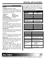
TECHNICAL SPECIFICATIONS
FEATURES/
DESCRIPTION
GENERAL
Input Connectors
USB
Ethernet/LAN
Control
Compatibility
> RS-232
> Relay contacts
> Real time clock
> Calendar
Real Time Clock/Alarms
Program repetitive tasks or one-time events up to a
year in advance. Execute macros to turn plasma on
or off at pre-determined times or intervals.
Pioneer Plasma TVs
Contact Relays
Four relays are available to control external events.
Each relay handles up to 24VDC at 1Amp. Turn
lights on or off, close or open drapes, or lower or
raise projectors. The PE1005 is fully integrated with
a one-year calendar and alarms.
Type A-female (1)
RJ-45 female (1)
25-pin HD female (1)
PDP504 Series
PDP434 Series
Table 1. PE1005 General
MECHANICAL
Weight
T° Operating
T° Maximum
Humidity
MTBF (calc.)
RS-232/RS-485
All functions on the plasma can be controlled using
RS-232 or RS-485 protocol. Decide which protocol
to use and the card handles the rest.
PE1005
0.5 lb (0.23 kg)
10°C to 35°C
0°C to 50°C
90% non-condensing
40,000 hrs
Table 2. PE1005 Mechanical
ELECTRICAL
Inputs
USB
Ethernet/LAN
25 PIN HD
IP Control
All functions of the card can be accessed through
Telnet or a Mini-web server. Choose the access
protocol and the PE1005 handles the details.
PE1005
Standard
TCP/IP 10/100
Max Capacity = 24VDC, 1A
Max Switching Current= 0.5A
Max Switching Power = 10VA
Input Ports
Open or Ground
MD+: MD Analog Out
Motion Detector (MD)
MD TRIG: MD Ext Trigger
9600 Baud
1 Stop Bits
RS-232/RS-485
Control
8 Data Bits
No Parity
Power
Pioneer Internal
+5.0V
90mA
+3.3V 120mA
Relays
Digital Inputs
Optically isolated digital inputs allow the user to
control a Pioneer Plasma from simple push buttons.
Wire them in and use them for remote on/off,
brightness up/down, input select, and more.
Proximity Detector (optional)
An ultrasonic proximity detector allows the
execution of any macro, based on the proximity and
direction of a target. Increase brightness as
customers get closer to the display; reduce
brightness as they move away, thus preventing
burnout on the screen and increasing the life of the
plasma display.
400-0384-003
PE1005
Table 3. PE1005 Electrical
3
3
SPECIAL APPLICATION
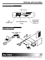
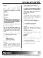
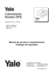
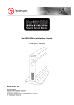
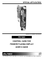
DESCRIPTION OF PE1005
4
25-PIN D-SUB
USB
CONNECTOR
APPLICATION DIAGRAMS
RJ-45 NETWORK JACK
CONNECTOR
TCP/IP
DIGITAL I/O
5
DIAGRAM 1: TYPICAL SETUP
400-0384-003
4
SPECIAL APPLICATION
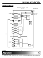
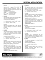
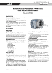
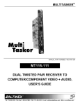
DIAGRAM 2: INTERNAL VIEW
PIONEER CONTROL CARD
PE1005
EDGE CONNECTOR
PE 1005
TX
TX PDP
RX PDP
ETHERNET
RJ-45
ETHERNET
TRANSCEIVER
TX
RX VIDEO CARD
TX
USB
TX/RX
RC-232
TX/RX
RS485
USB
TRANSCEIVER
TX
RS-232
to TTL
TX
RS485
TRANSCEIVER
11
OC
12
OC
13
OC
14
OC
D-SUB
25 PIN
MONITOR
DETECTOR
INPUT
TX
MAIN
MP
REAL
TIME
CLOCK
TX
INPUT
CONTROL
ADC
1
2
CONTACT
RELAYS
3
RELAY
CONTROL
POWER
4
400-0384-003
5
TX VIDEO CARD
SPECIAL APPLICATION
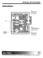
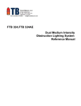
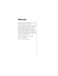
DIAGRAM 3: CARD DETAILS
P3
Test connector
used for circuit
card evaluation.
LED1
SW1
RS-232/RS-485
selection. The RS-232
position is shown.
BATTERY
3V Lithium
CR1225
400-0384-003
P5
Test connector
used for circuit
card evaluation.
6
SPECIAL APPLICATION
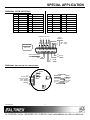
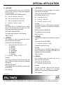
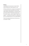
DIAGRAM 4: 25-PIN HD DETAILS
PIN
Description
PIN
1
Input 1
Description
PIN
5
Relay 1 Throw
13
GND
Description
21
Motion Det. +
2
3
4
Input 2
Input 3
Input 4
6
7
8
9
10
11
12
Relay 1 Pole
Relay 2 Throw
Relay 2 Pole
Relay 3 Throw
Relay 3 Pole
Relay 4 Throw
Relay 4 Pole
14
15
16
17
18
19
20
RS-232 TX
GND
RS-232 RX
GND
RS-485+
RS-485 GND
22
23
24
25
Motion Det. Trg.
GND
GND
GND
INTERNAL RELAYS
4
3
2
1
12 11 10
9
8
7
6
5
Description
INPUT
PORTS 1-4
4
3
2
1
GROUND PINS
13, 15, 17, 20
and 23 - 25
PIN
4
3
2
OFF = Open
ON = GND
1
1
13
25
14
22 21
19 18
16
14
Motion Detector (MD)
MD TRIGGER
MD+
TX RS-232
RX
+
-
RS485
DIAGRAM 5: MOTION DETECTOR DETAILS
RANGE
MIN
N/C
ANALOG OUT
PWM CLOCK OUT
TRIG.. ENABLE
EXT. TRIGGER
COMMON
+V
MAX
SCALE
1
GAIN
400-0384-003
7
CONNECTIONS
MOTION DET.
PE1005
MD+
Analog Out
Trig. Enable
Ground
Ext. Trigger
MD_TRIG
Common
Ground
+V
+5V
SPECIAL APPLICATION
INSTALLING YOUR PE1005
6
3.
Check for a “readme” file that may contain
special installation instructions. If there is a
“readme” file, print and read the contents
prior to running the application.
4.
Launch the application.
5.
Follow the instructions provided by the
Installation Wizard.
6.
Connect the PE1005 to the computer’s USB
port. The unit should be operational. If not, it
may be necessary to reboot the computer.
Step 1. Turn off the power to the plasma display.
Step 2. Use ESD safety precautions and always
wear a ground strap when handling the
PE1005.
Step 3. Prepare the card if necessary using the
application diagrams on page 7.
Step 4. Remove the card or cover currently
installed at the bottom of the display.
Step 5. Carefully insert the PE1005. Use the
thumbscrews to tighten the card securely
into place.
Note: In some cases, it is necessary to use the
Device Manager in Windows® and direct
Windows® to install the drivers located at
the path displayed during the installation
procedure in Step 5 above.
Step 6. If using RS-232 control, connect the
RS-232 communication port of the PC or
other control device to the PE1005
through the Digital I/O port using a 25-pin
HD
connector
and
cable.
See
DIAGRAM 4: 25-PIN HD DETAILS for
pinout information.
TCP/IP SETUP
1.
Download the “DeviceInstaller” for the XPort
device from the ALTINEX website,
www.altinex.com.
The “DeviceInstaller” is a configuration utility
for the Ethernet to serial controller. This
software
requires
Windows
.NET
Framework to be installed on the computer.
The .NET Framework should be revision 1.1
or later.
NOTE: RS-232 operation: Use AVSnap or
other RS-232 communication software.
Step 7. Turn on power to the plasma display.
EXTERNAL PORT SETUP
In addition to the controls available through the
25-pin HD connector, the PE1005 may also be
controlled through its USB or LAN ports. The
drivers required for configuring these ports are
available
on
the
ALTINEX
website,
www.altinex.com. If there are any questions or
difficulties installing these drivers, please call
ALTINEX at (714)-990-2300.
2.
3.
Connect the XPort device to the LAN using
standard CAT-5 cable.
USB SETUP
4.
The device must be installed in a system
and have power turned on in order to
proceed.
5.
Launch the Lantronix/DeviceInstaller from
the START menu or from the directory
noted earlier.
This will allow the
configuration of the XPort device.
1.
Download the TUSB3410 driver from the
ALTINEX website, www.altinex.com.
2.
Do not connect the PE1005 to the USB port
on the computer until after the drivers are
installed.
400-0384-003
Run the “setup.exe”
downloaded files.
file
from
the
This will install the DeviceInstaller on your
system. Make note of where the software is
installed on your computer.
8
SPECIAL APPLICATION
6.
Click on the “Search” button to check for
new devices on the LAN.
9.
When the command window appears, press
ENTER when prompted to enter Setup
Mode and then select the factory defaults.
10.
Next, select “Channel 1 Configuration”.
11.
View each line item as it appears. Press
ENTER to leave the default value, or enter
the new value and press ENTER.
NOTE: If you want to assign the IP manually, click
“Assign IP”. This method will require the
hardware address on the device and the
assistance of your IT Administrator.
THE IP ADDRESS
7.
Once the device is located, click on the
device in the installer window and make
note of the Internet address.
CONFIGURE THE DEVICE
8.
The device may be configured using a web
browser or using a Telnet session. This
procedure uses the Telnet option. Click the
“Telnet” button and do not change the
default port number of “9999”.
400-0384-003
NOTE: The “Port No.” in the configuration
menu is the COM port for use with
RS-232 communication software.
9
11.
Select “Save and Exit” to keep changes and
exit setup mode.
12.
Close the DeviceInstaller, setup is
complete. Use the port number assigned
above to communicate with the PE-1005
over the LAN.
SPECIAL APPLICATION
OPERATION
1. [STATUS]
7
This command displays the status of the
PE1005 and includes input status, relay
settings, assigned subroutines, and alarm
information.
7.1 RS-232 CONTROL
The PE1005 has many advanced remote control
capabilities, which are accessible through standard
RS-232 communication. Actual controlling may be
achieved using a computer control system or other
device capable of sending RS-232 commands.
Command Format: [STATUSCi]
Ci = Card ID (i = # from 1 to 99)
7.1.1 RS-232 INTERFACE
Example 1:
The RS-232 commands for the PE1005 are in a
simple ASCII character format.
1.
2.
Send the command [STATUS] and receive
feedback similar to the following:
Square brackets “[ ]” are part of the
command.
PE1005 Pioneer Control Card
IN:1111
IN#1=SUB NOT ASSIGNED
IN#2=SUB NOT ASSIGNED
IN#3=SUB NOT ASSIGNED
IN#4=SUB NOT ASSIGNED
TIME: 17:17:29
DATE: 06:08:05
DAY: Wednesday
Alarm 1 OFF SUB NOT ASSIGNED
Mode 1: once per second
Alarm 2 OFF SUB NOT ASSIGNED
Mode 1: once per minute
Int Baud Rate:9600
Motion Detector OFF
MD Threshold value:25
MD0=SUB NOT ASSIGNED
MD1=SUB NOT ASSIGNED
Use uppercase letters for all commands.
After processing a command, an “OK” will be
returned as feedback if the command is good.
“OK” will not be returned if the command
generates other feedback like the [RDRL]
command.
7.2 DESCRIPTION OF COMMANDS
The default unit ID is zero, but may be set to a
value from 1 to 99. In single unit operation,
commands may be sent without the unit
identifier. Unit ID 0 should be used for single unit
operation.
If multiple PE1005s are connected to the same
communication port, the units may be controlled
two ways. In order to control all the units the
same, commands may be sent without the unit
identifier. Commands sent without the unit
identifier will be executed by all PE1005s.
Example:
2. [FRESET]
[VER]:
Executed by all units.
[VERC1]: For Unit ID 1 Only
[VERC2]: For Unit ID 2 Only
etc.
This command is used to perform a factory reset
on the unit. All settings will be reset to default
values. This includes erasing subroutines,
clearing alarm settings, and resetting the time
and date values.
Individual control is accomplished by first
assigning each unit a unique ID number. Then
each unit may be controlled individually by
including the unit identifier at the end of each
command string.
400-0384-003
Command Format: [FRESETCi]
Ci = Unit ID (i = # from 1 to 99)
10
SPECIAL APPLICATION
5. [WAIT]
Example:
Reset the PE1005 with unit ID 1 to its default
settings by sending the command [FRESETC1].
The card will display a notice that a reset is in
process:
This command will cause the card to suspend
operation for specified period, up to ten
seconds. If several commands are present in a
single subroutine, use this command to make a
pause in between each command if desired.
PLEASE WAIT
CARD IS PERFORMING FACTORY RESET
Command Format: [WAITnCi]
When the reset is complete, the following
message will be displayed.
n
Ci = Unit ID (i = # from 1 to 99)
FACTORY RESET COMPLETED
Example:
3. [VER]
Send the command [WAIT10] to suspend
operation for one second before executing the
next function.
This command displays the firmware version
and model number of the PE1005.
6. [RDI]
Command Format: [VERCi]
Ci = Unit ID (i = # from 1 to 99)
This command is used to read the status of one
or more of the input ports. The ports are turned
on by connecting the corresponding input
connector pin to ground. (See page 7 for
details.) An open (no connection) on the input
pin is displayed as a ‘0’ for off. A ‘1’ indicates the
port is on (shorted to ground).
Example:
Send the command [VER] and receive the
following feedback:
PE1005 690-0205-002
PE1005
690-0205-002
= Delay time in 0.1sec (n=01~99)
= Model Number
= Firmware Version
Command Format: [RDInCi]
n
4. [TEST]
= input number (n = # from 1 to 4, * for all)
Ci = Unit ID (i = # from 1 to 99)
This command performs a test on the internal
memory. Upon completion, the system will
display the results.
Example 1:
Ci = Unit ID (i = # from 1 to 99)
The PE1005 has ports 1 and 2 on, while 3 and 4
are off. Send the command [RDI*] to read the
status of all the ports. The feedback will be as
follows:
Example:
1100
Send the command [TEST] to check the internal
card memory. The feedback will be similar to the
following:
Reading left to right, ports 1 and 2 show a ‘1’ for
on, and ports 3 and 4 show a ‘0’ for off.
Command Format: [TESTCi]
Example 2:
TIME: 17:18:28
DATE: 06:08:05
DAY: Wednesday
MEMORY TEST RESULTS:
U10: OK
U11: OK
Check the status of input one only by sending
the command [RDI1]. The feedback will be as
follows:
1
Otherwise, failures will be indicated.
400-0384-003
11
SPECIAL APPLICATION
7. [RDRL]
9. [WRRLk=x]
This command is used to read the status of one
or all of the internal relays. A ‘1’ indicates the
relay is on (closed). A ‘0’ indicates the relay is
off (open).
This command is used to set one or all internal
relays on or off. A ‘1’ will close the relay and a
‘0’ will open a relay.
Command Format: [WRRLk=xCi]
Command Format: [RDRLnCi]
n
= Relay No. (1, 2, 3, 4 or * for all)
Ci = Unit ID (i = # from 1 to 99)
k
= Relay No. (1, 2, 3, 4 or * for all)
x
= Relay Setting (0 = open, 1 = closed)
Ci = Unit ID (i = # from 1 to 99)
Example 1:
Example:
The PE1005 has relay number one on (closed)
and two through four are off. Send the command
[RDRL*] to check the status of all relays. The
feedback will be as follows:
Set only relay 1 on by sending the command
[WRRL1=1].
10. [WRIN]
Check the status of relay number one only by
sending the command [RDRL1]. The feedback
will be as follows:
This command is used to assign a subroutine
number to be executed when one of the input
ports makes a high-to-low transition. In order to
create a high-to-low transition, connect the input
port to ground using a switch or other contact
closure device.
1
Command Format: [WRINn=SUBkCi]
1000
Example 2:
8. [WRRLx1x2x3x4]
n
= Input No. (1, 2, 3 or 4)
This command is used to the turn the internal
relays on or off. A ‘1’ will close the relay, a ‘0’
will open a relay and an ‘X’ will leave the status
of the relay unchanged.
k
= Subroutine (k = # from 1 to 99)
Command Format: [WRRLx1x2x3x4Ci]
Assign subroutine 10 to be performed when port
one makes a high-to-low transition. In order to
do this, send the command [WRIN1=SUB10].
Now when input port one is shorted to ground,
subroutine 10 will be executed.
x1
x2
x3
x4
=
=
=
=
Ci = Unit ID (i = # from 1 to 99)
Example:
Relay #1
Relay #2
Relay #3
Relay #4
x = 0 for open, or off
x = 1 for closed or on
x = X for no change
11. [RDIN]
This command is used to read the subroutine
settings for the input ports.
Ci = Unit ID (i = # from 1 to 99)
Command Format: [RDINnCi]
Example:
n
Set relay 1 on, relay 4 off, and leave relays
2 and 3 unchanged. In order to do this, send the
command [WRRL1XX0].
Ci = Unit ID (i = # from 1 to 99)
400-0384-003
12
= Input No. (1, 2, 3, 4 or * for all)
SPECIAL APPLICATION
Example:
[WRS10=WRRL1=1,WAIT10,WRRL1=0;1]
Subroutine 10 is assigned to Input #1,
subroutine 20 is assigned to Input #2,
subroutine 30 is assigned to Input #3,
and subroutine 40 is assigned to Input #4. Send
the command [RDIN*] and receive the following
feedback:
[WRS10= SET1ALARM30800,ALRMON1;0]
Now send the command [RDS10] to read the
contents of subroutine 10. The feedback will be
as follows:
SUB10/NONE/: WRRL1=1,WAIT10,WRRL1=0,
SET1ALARM30800,ALRMON1
IN#1=SUB10
13. [WRLS]
IN#2=SUB20
This command is used to assign a label to a
subroutine. The label may be used to identify or
denote the purpose of the subroutine and may
be up to 8 characters long.
IN#3=SUB30
IN#4=SUB40
12. [WRS]
Illegal Characters:
The command is used to write functions to any
of 99 available subroutine memory locations. A
subroutine may be overwritten or appended for
long command function strings.
< > [ ] # $ % / \ |
Command Format: [WRLSm=<xxxxxxxx>Ci]
m
= Subroutine (m = # from 1 to 99)
x..x = Label Name (text characters)
Each location may contain up to 100 characters,
and a maximum of 24 characters may be written
to a subroutine at one time.
Ci = Unit ID (i = # from 1 to 99)
Example:
More than one function may be stored in a
single subroutine and multiple functions may be
written to memory in one command. When
sending multiple functions in a single command,
it is necessary to separate each function with a
comma.
Assign the text “SETALRM1” as the label for
subroutine 40 by sending the following
command:
[WRLS40=<SETALRM1>]
Command Format: [WRSm=F1,F2, F3...Fn ; pCi]
Next, send the command [RDLS40] and verify
the following feedback:
m
= Subroutine (m = # from 1 to 99)
SETALRM1
F
= Function (up to 25 characters at a time)
p
= Saving Instruction
14. [RDS]
This command displays the contents of one or
all subroutine memory locations. The subroutine
number, label, and stored data will be displayed.
0 append existing info
1 overwrite to existing info
Command Format: [RDSmCi]
Ci = Unit ID (i = # from 1 to 99)
m
Example:
Ci = Unit ID (i = # from 1 to 99)
A subroutine (sub 10) needs to store the
following functions: WRRL1=1, WAIT10,
WRRL1=0, WAIT10, SET1ALARM30800 and
ALRMON1. This is accomplished by sending the
following commands:
400-0384-003
= Subroutine (m = # from 1 to 99, * for all)
13
SPECIAL APPLICATION
17. [CLRLS]
Example:
Subroutine 20 is labeled “RLY_1_ON”. The
subroutine contains the function “WRRL1=1”.
Send the command [RDS20] and receive the
following feedback:
This command erases one or all subroutine
labels. Erasing the subroutine label does not
affect the contents of the subroutine.
k
SUB20/RLY_1_ON/: WRRL1=1
Ci = Unit ID (i = # from 1 to 99)
SUB20
= Subroutine Number
RLY_1_ON = Subroutine Label
WRRL1=1 = Stored Function
Example:
Subroutine 50 turns off all the relays and has the
label “RLYS_OFF”.
Send the command
[RDS50] and the display will be as follows:
15. [RDLS]
This command displays the subroutine label of
one or all subroutine memory locations.
SUB50/RLYS_OFF/: WRRL*=0
Clear the label for subroutine 50 by sending the
command [CLRLS50]. After sending this
command, reading the contents of subroutine 50
will be as follows:
Command Format: [RDLSmCi]
m
= Subroutine (m = # from 1 to 99, * for all)
Ci = Unit ID (i = # from 1 to 99)
SUB50/NONE/: WRRL*=0
Example:
18. [SUB]
Subroutine 20 is labeled “RLY_1_ON”. Send the
command [RDS20] and receive the following
feedback:
This command executes the functions stored in
a subroutine.
RLY_1_ON
Command Format: [SUBkCi]
16. [CLRS]
k
This command erases the subroutine contents
of one or all subroutine memory locations.
Erasing the subroutine contents does not affect
the subroutine label.
Example:
Subroutine 90 is programmed with the
command, [MDON], which enables the motion
detector. Send the command [SUB90], and the
motion detector will be enabled.
= Subroutine (n = # from 1 to 99, * for all)
19. [HELP]
Ci = Unit ID (i = # from 1 to 99)
Example:
This command displays a list of all RS-232
available commands.
Subroutine 50 turns off all the relays and has the
label “RLYS_OFF”.
Send the command
[RDS50] and the display will be as follows:
Command Format: [HELPCi]
Ci = Unit ID (i = # from 1 to 99)
SUB50/RLYS_OFF/: WRRL*=0
Example:
Clear the contents of subroutine 50 by sending
the command [CLRS50]. After sending this
command, reading the contents of subroutine 50
will be as follows:
Send the command [HELP] and a list of all
available commands, along with a brief
description, will be displayed.
SUB50/RLYS_OFF/Subroutine Empty
400-0384-003
= Subroutine (n = # from 1 to 99, * for all)
Ci = Unit ID (i = # from 1 to 99)
Command Format: [CLRSkCi]
k
= Subroutine (n = # from 1 to 99, * for all)
14
SPECIAL APPLICATION
20. [SETTIME]
22. [SETDATE]
This command sets the time for the PE1005
internal clock. The time is saved and displayed
in 24-hour format.
This command is used to program the internal
clock with the current date.
Command Format: [SETDATEmmddyyCi]
Command Format: [SETTIMEhhmmssCi]
mm = Month (mm=01 to 12)
hh = Time in hours (hh = 00 to 23)
dd = Date (dd=01 to 31)
mm = Time in minutes (mm = 00 to 59)
yy = Year (yy = 00 to 99)
ss = Time in seconds (ss = 00 to 59)
Ci = Unit ID (i = # from 1 to 99)
Ci = Unit ID (i = # from 1 to 99)
Example:
Example:
Set the date to June 1, 2005 and then read back
the date for verification by sending the following
commands.
The current time is 07:30AM. Set the internal
clock to this time and then verify the time is set
by sending the following commands:
[SETDATE060105] [RDDATE]
[SETTIME073000] [RDTIME]
The feedback will be as follows:
The display will be similar to the following:
DATE: 06-01-05
TIME: 07:30:05
23. [RDTIME]
21. [SETDAY]
This command reads back the time from internal
clock.
This command is used to program the internal
clock with the day of the week.
Command Format: [RDTIMECi]
Command Format: [SETDAYwCi]
w
Ci = Unit ID (i = # from 1 to 99)
=
day of the week (w = # from 1 to 7)
1 = Sunday
2 = Monday
3 = Tuesday
4 = Wednesday
5 = Thursday
6 = Friday
7 = Saturday
Ci = Unit ID (i = # from 1 to 99)
Feedback Format: hh:mm:ss
Example:
The current time is 08:40PM. Read back the
time by sending the command [RDTIME] and
receiving the following feedback:
TIME: 20:40:00
24. [RDDAY]
Example:
This command reads the current day of the
week from the internal clock.
Set the day to Monday and then read back the
day to verify the setting by sending the following
commands:
Command Format: [RDDAYCi]
Ci = Unit ID (i = # from 1 to 99)
[SETDAY2] [RDDAY]
Example:
The feedback from the [RDDAY] command will
be as follows:
The day is Monday. Read the day from the
internal clock by sending the command
[RDDAY] and receiving the following feedback:
DAY: Monday
DAY: Monday
400-0384-003
15
SPECIAL APPLICATION
25. [RDDATE]
This is an example only. These or other functions
may be programmed into the subroutine in order to
control external equipment, set indicator lights, or
trigger external events as desired.
This command reads the date from the internal
clock.
Command Format: [RDDATECi]
26. [SET1ALRM1] – MODE 1 - Every Minute
Ci = Unit ID (i = # from 1 to 99)
This command is used to set Alarm #1 into
Mode 1.
Example:
The date is June 13, 2005. Read back the
current date setting by sending the command
[RDDATE] and receive the following feedback:
Command Format: [SET1ALRM1ssCi]
ss = Time in seconds (ss = 00 to 59)
Ci = Unit ID (i = # from 1 to 99)
DATE: 06-13-05
Example:
ALARM #1 COMMANDS
Associate Alarm #1 with subroutine 10 and set
Alarm #1 to trigger 30 seconds into each minute
by sending the following commands:
The PE1005 has two programmable alarms, which
may be programmed to execute functions stored in
subroutines. The first alarm has five modes to
choose from, but only one mode may be active at a
time. The following Alarm #1 modes allow the alarm
to be executed at one of the following rates:
Mode 1
Mode 2
Mode 3
Mode 4
Mode 5
=
=
=
=
=
[ALRM1=SUB10]
[SET1ALRM130]
[ALRMON1]
Every Minute
Every Hour
Every Day
Every Month
Every Week
Alarm #1 is now enabled and running. Every
minute when the second count matches “30”,
the functions stored in subroutine 10 will be
executed. If the time is 10:00:00AM, the alarm
will trigger at the following times:
The following is required for the alarm to function:
10:00:30
1. Set the Time, Day and Date on the PE1005.
10:01:30
2. Program functions into a subroutine.
10:01:30 etc.
27. [SET1ALRM2] – MODE 2 - Every Hour
3. Associate the subroutine with an alarm.
This command is used to set Alarm #1 into
Mode 2.
4. Set the alarm number and mode.
5. Enable the alarm.
Command Format: [SET1ALRM2mmssCi]
The alarm functions that follow are used to setup
the alarms and enable/disable the alarms. The
examples used in the next commands reference
subroutine 10 and assume the time and date are
already set. Subroutine 10 is programmed to close
internal relay number one, wait a half-second and
then open the relay.
mm = Time in Minutes (mm = 00 to 59)
ss = Time in Seconds (ss = 00 to 59)
Ci = Unit ID (i = # from 1 to 99)
[WRS10=WRRL1=1,WAIT5, WRRL1=0;1]
400-0384-003
16
SPECIAL APPLICATION
29. [SET1ALRM4] – MODE 4 - Once A Month
Example:
Associate Alarm #1 with subroutine 10 and set
Alarm #1 to trigger at the bottom of every hour
by sending the following commands:
This command is used to set Alarm #1 into
Mode 4.
Command Format: [SET1ALRM4hhmmssddCi]
[ALRM1=SUB10]
hh = Time in Hours (hh = 00 to 23)
[SET1ALRM23000]
mm = Time in Minutes (mm = 00 to 59)
[ALRMON1]
ss = Time in Seconds (ss = 00 to 59)
Alarm #1 is now enabled and running. Every
hour when the minute and second counts match
“30:00”, the functions stored in subroutine 10 will
be executed. If the time is 10:30:00AM, the
alarm will trigger at the following times:
dd = Date (dd = 01 to 31)
Ci = Unit ID (i = # from 1 to 99)
Example:
11:30:00
Associate Alarm #1 with subroutine 10 and set
Alarm #1 to trigger at 2:30PM on the 15th day of
the month by sending the following commands:
12:30:00 etc.
[ALRM1=SUB10]
10:30:00
[SET1ALRM414300015]
28. [SET1ALRM3] – MODE 3 - Once A Day
[ALRMON1]
This command is used to set Alarm #1 into
Mode 3.
Alarm #1 is now enabled and running. Every
month on the 15th at 2:30PM the functions
stored in subroutine 10 will be executed.
Command Format: [SET1ALRM3hhmmssCi]
hh = Time in Hours (hh = 00 to 23)
30. [SET1ALRM5] – MODE 5 - Once A Week
mm = Time in Minutes (mm = 00 to 59)
This command is used to set Alarm #1 into
Mode 5.
ss = Time in Seconds (ss = 00 to 59)
Ci = Unit ID (i = # from 1 to 99)
Command Format: [SET1ALRM5hhmmsswCi]
Example:
hh = Time in Hours (hh = 00 to 23)
Associate Alarm #1 with subroutine 10 and set
Alarm #1 to trigger at 12 noon every day by
sending the following commands:
mm = Time in Minutes (mm = 00 to 59)
ss = Time in Seconds (ss = 00 to 59)
w
[ALRM1=SUB10]
= Day of the Week (w = 1 to 7)
1 = Sunday
2 = Monday
3 = Tuesday
4 = Wednesday
5 = Thursday
6 = Friday
7 = Saturday
[SET1ALRM3120000]
[ALRMON1]
Alarm #1 is now enabled and running. Every day
at noon the functions stored in subroutine 10 will
be executed.
Ci = Unit ID (i = # from 1 to 99)
400-0384-003
17
SPECIAL APPLICATION
31. [SET2ALRM1] – MODE 1 - Every Minute
Example:
Associate Alarm #1 with subroutine 10, and set
Alarm #1 to trigger at 10:00AM every Tuesday,
by sending the following commands:
This command is used to set Alarm #2 into
Mode 1.
Command Format: [SET2ALRM1Ci]
[ALRM1=SUB10]
Ci = Unit ID (i = # from 1 to 99)
[SET1ALRM51000003]
Example:
[ALRMON1]
Associate Alarm #2 with subroutine 10 and set
Alarm #2 to trigger each minute at “00” by
sending the following commands:
Alarm #1 is now enabled and running. Every
Tuesday at 10:00AM the functions stored in
subroutine 10 will be executed.
[ALRM2=SUB10]
ALARM #2 COMMANDS
[SET2ALRM1]
The second programmable alarm for the PE1005
has five modes to choose from, but only one mode
may be active at a time. The following Alarm #2
modes allow the alarm to be executed at one of the
following rates:
[ALRMON2]
Mode 1
Mode 2
Mode 3
Mode 4
Mode 5
=
=
=
=
=
Alarm #2 is now enabled and running. Every
minute when the second count matches “00”,
the functions stored in subroutine 10 will be
executed. If the time is 09:59AM, the alarm will
trigger at the following times:
Every Minute
Every Hour
Every Day
Every Month
Every Week
10:00:00, 10:01:00, 10:02:00 …
32. [SET2ALRM2] – MODE 2 - Every Hour
This command is used to set Alarm #2 into
Mode 2.
The following is required for the alarm to function:
Command Format: [SET2ALRM2mmCi]
1. Set the Time, Day and Date on the PE1005.
mm = Time in Minutes (mm = 00 to 59)
2. Program functions into a subroutine.
Ci = Unit ID (i = # from 1 to 99)
3. Associate the subroutine with an alarm.
Example:
4. Set the alarm number and mode.
Associate Alarm #2 with subroutine 10 and set
Alarm #2 to trigger at the bottom of every hour
by sending the following commands:
5. Enable the alarm.
The alarm functions that follow are used to setup
the alarms and enable and disable the alarms. The
examples used in the next commands reference
subroutine 10 and assume the time and date are
already set. Subroutine 10 is programmed to close
internal relay number one, wait a half-second and
then open the relay.
[ALRM2=SUB10]
[SET2ALRM230]
[ALRMON2]
[WRS10=WRRL1=1,WAIT5, WRRL1=0;1]
This is an example only. These or other functions
may be programmed into the subroutine in order to
control external equipment, set indicator lights or
trigger external events as desired.
400-0384-003
18
SPECIAL APPLICATION
Alarm #2 is now enabled and running. Every
hour when the minute and second count
matches “30:00”, the functions stored in
subroutine 10 will be executed. If the time is
10:29:00AM, the alarm will trigger at the
following times:
Example:
10:30:00
[SET2ALRM4143015]
11:30:00
[ALRMON2]
12:30:00 etc.
Alarm #1 is now enabled and running. Every
month on the 15th at 2:30PM, the functions
stored in subroutine 10 will be executed.
Associate Alarm #2 with subroutine 10 and set
Alarm #2 to trigger at 2:30PM on the 15th day of
the month by sending the following commands:
[ALRM2=SUB10]
33. [SET2ALRM3] – MODE 3 - Once A Day
This command is used to set Alarm #2 into
Mode 3.
35. [SET2ALRM5] – MODE 5 - Once A Week
This command is used to set Alarm #2 into
Mode 5.
Command Format: [SET2ALRM3hhmmCi]
hh = Time in Hours (hh = 00 to 23)
Command Format: [SET2ALRM5hhmmwCi]
mm = Time in Minutes (mm = 00 to 59)
hh = Time in Hours (hh = 00 to 23)
Ci = Unit ID (i = # from 1 to 99)
mm = Time in Minutes (mm = 00 to 59)
Example:
w
Associate Alarm #2 with subroutine 10 and set
Alarm #2 to trigger at 12 noon every day by
sending the following commands:
= Day of the Week (w = 1 to 7)
1 = Sunday
2 = Monday
3 = Tuesday
4 = Wednesday
5 = Thursday
6 = Friday
7 = Saturday
Ci = Unit ID (i = # from 1 to 99)
[ALRM2=SUB10]
[SET2ALRM31200]
[ALRMON2]
Alarm #2 is now enabled and running. Every day
at noon, the functions stored in subroutine 10
will be executed.
Example:
Associate Alarm #2 with subroutine 10, and set
Alarm #2 to trigger at 10:00AM every Tuesday
by sending the following commands:
34. [SET2ALRM4] – MODE 4 - Once A Month
This command is used to set Alarm #2 into
Mode 4.
[ALRM2=SUB10]
Command Format: [SET2ALRM4hhmmddCi]
[SET2ALRM510003]
hh = Time in Hours (hh = 00 to 23)
[ALRMON2]
mm = Time in Minutes (mm = 00 to 59)
Alarm #2 is now enabled and running. Every
Tuesday at 10:00AM, the functions stored in
subroutine 10 will be executed.
dd = Date (dd = 01 to 31)
Ci = Unit ID (i = # from 1 to 99)
400-0384-003
19
SPECIAL APPLICATION
39. [ALRMn=SUBk]
ALARM CONTROLS
This command sets the dependencies between
an alarm and a subroutine. The functions in the
subroutine will be executed when the alarm
conditions are met.
36. [ALRMON]
This command activates Alarm #1 and
Alarm #2. After turning the alarm on, the
functions assigned to the alarm with the
[ALRMn=SUBk] command will be executed at
the alarm time.
Command Format: [ALRMn=SUBkCi]
n
= Alarm Number (n = 1 or 2)
Command Format: [ALRMONnCi]
k
= Subroutine (k = # from 1 to 99)
n
Ci = Unit ID (i = # from 1 to 99)
= Alarm No. (n = 1 or 2)
Ci = Unit ID (i = # from 1 to 99)
Example:
Example:
Assign subroutine 20 to be executed when the
conditions for Alarm #2 are met by sending the
command
[ALRM2=SUB20].
Use
the
[RDALRM2] command to verify the setting.
Turn on Alarm #1 on by sending the command
[ALRMON1]. Alarm #1 is now enabled.
37. [ALRMOFF]
RS-232 MEMORY COMMANDS
This command deactivates Alarm #1 and
Alarm #2. After turning the alarm off, nothing will
happen at the alarm time.
40. [WRM]
This command saves RS-232 data into memory.
This memory is not the same as the memory for
subroutine storage. When writing to the memory
location, the memory may be overwritten or
appended with this command.
Command Format: [ALRMOFFnCi]
n
= Alarm No. (n = 1 or 2)
Ci = Unit ID (i = # from 1 to 99)
Example:
Command Format: [WRMm=xxxxxx;pCi]]
Turn on Alarm #2 off by sending the command
[ALRMOFF1]. Alarm #2 is now disabled.
38. [RDALRM]
m
= Memory Location (m = # from 1 to 99)
x
= Data
16 characters may be sent at a time
112 characters total per memory location
This command reads back an alarm’s settings.
Command Format: [RDALRMnCi]
n
p
= Alarm No. (n = 1 or 2)
0 append to existing info
1 overwrite existing info
Ci = Unit ID (i = # from 1 to 99)
Example:
Ci = Unit ID (i = # from 1 to 99)
Subroutine 90 is assigned to Alarm #1, and
Alarm #1 is set to go off at 30 minutes past
every hour. Send the command [RDALRM1] and
receive feedback similar to the following:
Alarm 1 ON SUB90
Mode 3: When minutes and seconds match 30:00
400-0384-003
= Saving Instruction
20
SPECIAL APPLICATION
Hex characters can be added to the string by
using the % sign in front of the hex number.
Sending %0C will send the hex “0C”, or form
feed character. The three characters making up
the hex number cannot be separated and must
be in the same string. Below are some common
hex numbers:
Example:
%5B = ‘ [ ‘
%7B = ’ { ‘
%3C = ' < '
…
Read back the contents of all the memory
locations by sending the command [RDM*]. The
feedback will be in the following format:
MEM1/NONE/: ON
MEM2/NONE/: OFF
%5D = ' ] '
%7D = ' } '
%3E = ' > '
MEM99/NONE/Memory Empty
43. [RDLM]
Example:
This command displays the data for one or all
memory location labels.
Program RS memory location 50 with the string
“STANDBY_ON” by sending the command
[WRM50=STANDBY_ON;1].
Using the ‘1’
option, this will overwrite whatever information is
currently in location 50 and save the command
“STANDBY_ON”.
Command Format: [RDLMmCi]
m
= Memory Location (m = 1 to 99, * for all)
Ci = Unit ID (i = # from 1 to 99)
41. [WRLM]
Example:
This command assigns a label to a memory
location. This label can help identify the contents
or function of the data stored in the memory
location. The label may be up to eight
characters.
Read back the contents of all the memory labels
by sending the command [RDLM*]. The
feedback will be in the following format:
Command Format: [WRLMm=<xxxxxx>Ci]
MEM2:PLAY
m
= Memory Location (m = # from 1 to 99)
…
x
= Label Name (8 characters max)
MEM99:NONE
MEM1:STOP
44. [CLRM]
Ci = Unit ID (i = # from 1 to 99)
This command clears one or all RS-232 memory
location. The memory for the subroutines is not
affected.
Example:
Add the label “STANDBY” to memory location
50
by
sending
the
command
[WRLM50=<STANDBY>].
Command Format: [CLRMmCi]
m
42. [RDM]
Ci = Unit ID (i = # from 1 to 99)
This command displays the data for one or all
memory locations. The data shows the memory
location number, the memory label and then the
contents of the memory location.
Example:
Clear the contents of all RS-232 memory
locations by sending the command [CLRM*].
The PE1005 will respond with the following
feedback:
Command Format: [RDMmCi]
m
= Memory Location (m = 1 to 99, * for all)
= Memory Location (m = 1 to 99, * for all)
ALL SUBS WILL BE CLEARED
Ci = Unit ID (i = # from 1 to 99)
PLEASE WAIT
400-0384-003
21
SPECIAL APPLICATION
47. [RDRSI]
Upon completion, the following message will be
displayed.
Reads baud rate for internal RS-232 bus
communication.
TASK COMPLETED
45. [CLRLM]
Command Format: [RDRSICi]
This command clears one or all RS-232 memory
location labels.
Ci = Unit ID (i = # from 1 to 99)
Example:
Command Format: [CLRLMkCi]
k
Send the command [RDRSI] to read back the
internal RS-232 baud rate. The feedback will be
similar to the following:
= Memory Location (m = 1 to 99, * for all)
Ci = Unit ID (i = # from 1 to 99)
9600
Example:
48. [OUTRSM]
Clear the contents of all RS-232 memory
location labels by sending the command
[CLRLM*]. The PE1005 will respond with “OK”
when the labels are cleared.
This command sends the contents of an RS
memory location to the external RS-232 port.
Command Format: [OUTRSMmCi]
COMMUNICATION
m
The next several commands deal with internal and
external communication.
Ci = Unit ID (i = # from 1 to 99)
46. [MODERSI]
Output the contents of RS memory location 99
to the external RS-232 bus by sending the
command [OUTRSM99]. The characters stored
in memory location 99 will be output on the
external RS-232 bus.
Example:
This command is used to set the baud rate for
the internal RS-232 bus communication.
Command Format: [MODERSImCi]
m
= Baud Rate bps
49. [OUTBSM]
=
2400
=
4800
=
9600
=
19200
=
38400
Ci = Unit ID (i = # from 1 to 99)
This command sends RS memory data through
the internal RS-232 port/bus.
Command Format: [OUTBSMmCi]
m
= Memory Location (m = # from 1 to 99)
Ci = Unit ID (i = # from 1 to 99)
Example:
Set the internal baud rate to 9600 baud by
sending the command [MODERSI9600]. Use
the [STATUS] or [RDRSI] commands to verify
this setting. In the status feedback, this setting
will be as follows:
Example:
Send the contents of RS memory location 50 to
the internal bus by sending the command
[OUTBSM50].
Int Baud Rate:9600
50. [OUTPDPM]
The feedback from the [RDRSI] command will
simply be “9600”.
400-0384-003
= Memory Location (m = # from 1 to 99)
This command sends RS memory data through
the internal RS-232 port/bus to the Display PDP
card.
22
SPECIAL APPLICATION
53. [SENDBS]
Command Format: [OUTPDPMmCi]
m
= Memory Location (m = # from 1 to 99)
This command sends direct data through the
internal RS-232 bus based on the Plasma
display’s internal control settings. The data
between the “< >”s is sent to the bus.
Ci = Unit ID (i = # from 1 to 99)
Example:
Send the contents of RS memory location 10 to
the internal bus to the Display PDP card by
sending the command [OUTPDPM10].
Command Format: [SENDBS<xxx>Ci]
xxx = ASCII Characters (16 maximum)
Ci = Unit ID (i = # from 1 to 99)
51. [OUTVCM]
Example:
This command sends RS memory data through
the internal RS-232 port/bus to the Video card.
Output the string “STANDBY” by sending the
following command, [SENDBS<STANDBY>].
Command Format: [OUTVCMmCi]
m
54. [SENDPS]
= Memory Location (m = # from 1 to 99)
This command sends data directly through the
internal RS-232 bus to the main control card.
The data between the “< >”s is sent to the bus.
Ci = Unit ID (i = # from 1 to 99)
Example:
Send the contents of RS memory location 1 to
the internal bus to the Video card by sending the
command [OUTVCM1].
Command Format: [SENDPS<xxx>Ci]
xxx = ASCII Characters (16 maximum)
Ci = Unit ID (i = # from 1 to 99)
DIRECT DATA
Example:
The next four commands allow data to be sent
directly to the RS-232 bus/port without using data
stored in memory locations.
Send the string “INPUT” by sending the
following command, [SENDPS<INPUT>].
55. [SENDVS]
Hex characters may be sent using the ‘%’ sign
followed by two bytes of hex data. Sending %0C
will send the hex “0C”, or form feed character. The
three characters making up the hex number cannot
be separated and must be in the same string.
This command sends data directly through the
internal RS-232 bus to the video card. The data
between the “< >”s is sent to the bus.
Command Format: [SENDVS<xxx>Ci]
52. [SENDRS]
xxx = ASCII Characters (16 maximum)
This command sends direct data through the
external RS-232 port. The data between the
“< >”s is sent to the bus.
Ci = Unit ID (i = # from 1 to 99)
Command Format: [SENDRS<xxx>Ci]
Send the string “INPUT” by sending the
following command, [SENDVS<INPUT>].
Example:
xxx = ASCII Characters (16 maximum)
Ci = Unit ID (i = # from 1 to 99)
Example:
Output the string “PAGE 1” followed by a form
feed by sending the following command,
[SENDRS<PAGE 1%0C>].
400-0384-003
23
SPECIAL APPLICATION
Example:
MOTION DETECTOR
MDON, MDOFF, MD1, MD0, SETMD RDMD
Assign subroutine 10 to be executed when an
object is sensed moving toward the motion
detector
by
sending
the
command
[MD1=SUB10].
The next commands setup and control the motion
detector. [SETMD] sets the trigger level and [MD0]
and [MD1] assign subroutines to be executed
depending on the direction of motion. [RDMD]
displays the motion detector settings and [MDON]
and [MDOFF] activate and deactivate the detector.
59. [MD0]
This command assigns a subroutine to be
executed when an object is sensed moving
away from the motion detector.
56. [MDON]
This command activates the external motion
detector. The motion detector settings must first
be defined using the [SETMD], [MD0] and [MD1]
commands.
Command Format: [MD0=SUBkCi]
Command Format: [MDONCi]
Example:
Ci = Unit ID (i = # from 1 to 99)
Assign subroutine 11 to be executed when an
object is sensed moving away from the motion
detector
by
sending
the
command
[MD1=SUB11].
k
= Subroutine (k = # from 1 to 99)
Ci = Unit ID (i = # from 1 to 99)
Example:
Send the command [MDON] to activate/enable
the motion detector.
60. [SETMD]
57. [MDOFF]
This command is used to deactivate/disable the
motion detector.
This command sets the motion detector’s trigger
level. The trigger level range is 0.1V to 5.0V and
may be set in increments of 0.1V.
Command Format: [MDOFFCi]
Command Format: [SETMD=xCi]
Ci = Unit ID (i = # from 1 to 99)
x
Example:
01 = 0.1V
02 = 0.2V
…
50 = 5.0V
Ci = Unit ID (i = # from 1 to 99)
Send the command [MDOFF] to disable the
motion detector. None of the settings will be
affected, but the motion detector will not be
actively sensing for motion.
Example:
58. [MD1]
Set the trigger level a value of 1.0V by sending
the command [SETMD=10]. Use the [RDMD]
command to read values and check settings.
This command is used to assign a subroutine to
be executed when an object is sensed moving
toward the motion detector.
61. [SETTMD]
Command Format: [MD1=SUBkCi]
k
This command sets the motion detector’s time
delay. The sensor will trigger until a target is
found and then stop sensing and not check for a
new target until after the specified delay time.
The range is 01 to 99, where each increment is
0.1 minutes and the minimum delay time is
6 seconds.
= Subroutine (k = # from 1 to 99)
Ci = Unit ID (i = # from 1 to 99)
400-0384-003
= Trigger Level (x = # from 01 to 50)
24
SPECIAL APPLICATION
Command Format: [SETMD=xCi]
Example:
x
The motion detector’s trigger level is set to 1.0V.
Subroutine 10 is assigned for objects moving
away from the detector, and subroutine 11 is
assigned for objects moving toward the detector.
Send the command [RDMD] and receive
feedback similar to the following:
= Time Delay (x = # from 01 to 99)
01 = 0.1 minutes (6 sec)
02 = 0.2 minutes (12 sec)
…
99 = 9.9 minutes
Ci = Unit ID (i = # from 1 to 99)
Motion Detector ON
Example:
MD Current value:04
Set the time delay to a value of one minute by
sending the command [SETTMD=10]. Use the
[RDMD] command to read values and check
settings.
MD Threshold value:10
MD0=SUB10
MD1=SUB11
62. [MDTYPE]
This command sets the motion detector’s time
delay. The sensor will trigger until a target is
found and then stop sensing and not check for a
new target until after the specified delay time.
The range is 01 to 99, where each increment is
0.1 minutes and the minimum delay time is
6 seconds.
ID COMMANDS – RSI, SIDn, SIDnCi, RSN
64. [RSI]
This command resets the card IDs in the
system. After sending this command, each card
ID will be ‘0’.
Command Format: [RSI]
Command Format: [MDTYPE=xCi]
x
Example:
= Sensor Type (x = 0 or 1)
Send the command [RSI] to the system with
ID 2. The card can no longer be recognized as
ID 2, it will be ID 0.
0 = Ultrasound Motion Detector
1 = PIR Motion Detector
Ci = Unit ID (i = # from 1 to 99)
REMEMBER: A command sent without the unit
ID will be executed by all the
PE1005s connected to the
RS-232 port.
65. [SIDn]
Example:
Set the time delay to a value of one minute by
sending the command [SETTMD=10]. Use the
[RDMD] command to read values and check
settings.
This command sets the ID number of all cards
connected to the RS-232 bus to the same value.
The default unit ID is zero.
63. [RDMD]
Use this command to display the motion
detector’s settings and check its status. The
status
includes
the
settings,
assigned
subroutines, current detected reading, and
whether or not the motion detector is active.
Command Format: [SIDn]
n
Example:
Send the command [SID1] to the system. The
card ID is now one, and “C1” must be included
at the end of each command line, as in
“[VERC1]”, for only the unit with ID1 to respond.
Command Format: [RDMDCi]
Ci = Unit ID (i = # from 1 to 99)
400-0384-003
= New ID (n = # from 1 to 99)
25
SPECIAL APPLICATION
13) [WRLS]
Write a subroutine label
14) [RDS]
Display subroutine data
15) [RDLS]
Display a subroutine label
16) [CLRS]
Erase subroutine contents
This command sets the ID number of a single
card to a new ID number. Only the cards that
have the matching ID will be changed.
17) [CLRLS]
Erase subroutine label
18) [SUB]
Execute a subroutine
19) [HELP]
Show RS-232 commands
Command Format: [SIDnCi]
20) [SETTIME]
Set the time of day
n
21) [SETDAY]
Set the day of the week
22) [SETDATE]
Set the day/month/year
23) [RDTIME]
Display internal time
24) [RDDAY]
Display day of the week
REMEMBER: A command sent without the unit
ID will be executed by all the
PE1005s connected to the
RS-232 port.
66. [SIDnCi]
= New ID (i = # from 1 to 99)
Ci = Card ID (n = # from 1 to 99)
Example:
Send the command [SID10C1] to the bus. The
card with the ID of “C1” will now become “C10”.
Now “C10” must be included at the end of the
command string for only that card to respond.
25)
26)
27)
28)
29)
30)
31)
32)
33)
34)
35)
36)
37)
38)
39)
40)
41)
42)
43)
44)
45)
67. [RSN]
This command reads and then displays the ID
number of the unit.
Command Format: [RSN]
Example:
The PE1005 was set to an ID value of 3. Send
the command [RSN] and the system will return
the following feedback:
PE1005 ID#3
7.3 SUMMARY OF COMMANDS
1)
[STATUS]
Display card status
2)
[FRESET]
Reset card default values
3)
[VER]
Display firmware version
4)
[TEST]
Test memory ICs
5)
[WAIT]
Suspend operation
6)
[RDI]
Display input port status
7)
[RDRL]
Display relay status
8)
[WRRLx1x2x3x4] Set individual relays
9)
[WRRLk=x]
Set one or all relays
10) [WRIN]
Assign sub to input port
11) [RDIN]
Read input port subs
12) [WRS]
Write a subroutine
400-0384-003
26
[RDDATE]
Display date from clock
[SET1ALRM1] Set Alarm 1 Mode 1
[SET1ALRM2] Set Alarm 1 Mode 2
[SET1ALRM3] Set Alarm 1 Mode 3
[SET1ALRM4] Set Alarm 1 Mode 4
[SET1ALRM5] Set Alarm 1 Mode 5
[SET2ALRM1] Set Alarm 2 Mode 1
[SET2ALRM2] Set Alarm 2 Mode 2
[SET2ALRM3] Set Alarm 2 Mode 3
[SET2ALRM4] Set Alarm 2 Mode 4
[SET2ALRM5] Set Alarm 2 Mode 5
[ALRMON]
Activate Alarm
[ALRMOFF]
Deactivate Alarm
[RDALRM]
Read alarm settings
[ALRMn=SUBk] Set Alarm Dependencies
[WRM]
Write a memory location
[WRLM]
Write a memory label
[RDM]
Display memory data
[RDLM]
Display memory label
[CLRM]
Erase memory location
[CLRLM]
Erase memory label
SPECIAL APPLICATION
46) [MODERSI]
Set internal baud rate
47) [RDRSI]
Read internal baud rate
48) [OUTRSM]
Send memory
external RS-232
data
via
49) [OUTBSM]
Send memory
internal RS-232
data
via
50) [OUTPDPM]
Send memory data
plasma main card
to
51) [OUTVCM]
Send memory data
plasma video card
to
52) [SENDRS]
Send data via external bus
53) [SENDBS]
Sends data via internal bus
54) [SENDPS]
Send data to display card
55) [SENDVS]
Send data to video card
56) [MDON]
Enable motion detector
57) [MDOFF]
Disable motion detector
58) [MD1]
Set approaching sub
59) [MD0]
Set departing sub
60) [SETMD]
Set detector trigger value
61) [SETTMD]
Set detector time delay
62) [MDTYPE]
Set detector type
63) [RDMD]
Read detector settings
64) [RSI]
Reset card ID
65) [SIDn]
Set ID of cards
66) [SIDnCi]
Set ID of a single card
67) [RSN]
Read ID number
As in the previous sections, commands are sent via
standard RS-232 communication. Commands may
be sent directly to the internal bus, or stored into
RS memory locations and recalled from the
memory location and sent to the bus. The
commands for communicating with the internal bus
are [OUTPDPM] and [SENDBS]. See the previous
sections for details on these two commands,
including restrictions on the number of characters
that may be stored or sent in a single command.
7.4.1 INTERNAL COMMAND FORMAT
The internal commands for the PE1005 are in
the following format and must contain the
protocols indicated:
Start of text. (STX)
Plasma ID (default)
Command ID
%02
%2A%2A
4.
End of text. (ETX)
%03
See Appendix A of the
Pioneer manual
mentioned earlier.
7.4.2 SENDING COMMANDS TO INTERNAL BUS
The default baud rate for the PE1005 is 9600
baud. Prior to sending any commands, verify
both the plasma and PE1005 are set to 9600
baud.
In order to change setting values, the plasma
must be in adjustment mode. The plasma may
be placed into adjustment mode by sending the
command AJY.
7.4 PLASMA CONTROL WITH INTERNAL BUS
The
following
examples
demonstrate
communication with the plasma through the
internal bus using both stored commands and
direct commands. All commands may be sent to
the plasma using either method.
The PE1005 has the capability of sending
commands directly to the plasma’s internal bus or
to third-party video cards installed in the plasma.
This allows the user to control settings on the
display without having to use the menu buttons on
the display or with the remote control.
400-0384-003
1.
2.
3.
Example 1: Adjustment Mode
Place the plasma into adjustment mode by
sending the following command directly to the
internal bus:
[SENDBS<%02%2A%2AAJY%03>]
27
SPECIAL APPLICATION
Example 2: Adjust Brightness
Now that the plasma is in adjustment mode,
various settings may be changed. Set the
brightness to a value of 100 by sending the
following commands directly to the internal bus:
[SENDBS<%02%2A%2A>]
[SENDBS<BRT150%03>]
NOTE:
Pioneer Manual:
www.pioneerelectronics.com/pio/pe
/images/portal/cit_3424/164151803
PDP504CMX_RS232-CPM.pdf
Some of the commands and features in the guide
will only be available depending on the model and
options of the Pioneer display.
The [SENDBS] command can only
send 16 characters at a time. Break
the command into smaller sections if
necessary, or store the entire
command in a memory location.
TROUBLESHOOTING GUIDE
We have carefully tested and have found no
problems in the supplied PE1005. However, we
would like to offer suggestions for the following:
Example 3: Select Inputs
Select between Input 1 and Input 2. This time,
use commands that are stored in memory.
First program memory locations 10 and 20 with
the input select commands. Memory location 10
will store the IN1 command and location 20 will
store the IN2 command. Send the IN1 and IN2
commands along with the STX, ID and ETX
portions of the command by sending the
following:
[WRM10=%02%2A%2A;1]
Write location 10.
[WRM10=IN1%03;0]
Append location 10.
[WRM20=%02%2A%2A;1]
Write location 20.
[WRM20=IN2%03;0]
Append location 20.
8
8.1 THERE IS NO COMMUNICATION
Second, recall the commands from memory and
send them to the internal bus using the following
commands:
Cause 1:
There is a setup problem.
Solution:
Check the communication software
and verify the PE1005 is connected
to the correct communication port
and that the software is connected.
If there is still no response, see
Cause 2.
Cause 2:
The connection is wrong.
Solution:
Verify the RS-232 cabling is correct.
The RS-232 transmit and receive
pins are pins 14 and 16 of the 25-pin
HD connector. If there is still no
response, please call ALTINEX at
(714)-990-2300.
8.2 RELAYS DO NOT WORK
[OUTPDPM10]
Select Input 1
Cause 1:
The cabling is incorrect.
[OUTPDPM20]
Select Input 2
Solution:
See DIAGRAM 4: 25-PIN HD
DETAILS for connection details. If
the cabling is good and the relays
still do not switch, see Cause 2.
Cause 2:
The correct relay does not switch.
Solution:
There are four internal relays, 1
through 4. Turn on all the relays by
sending the command [WRRL*=1].
If some of the relays are open,
please
call
ALTINEX
at
(714)-990-2300.
7.5 PIONEER PLASMA COMMANDS
A detailed listing of RS-232 commands is available
in the PDP-504CMX Command Protocol Manual
available on the Pioneer Electronics website.
Please see the following links.
Pioneer website:
www.pioneerelectronics.com
400-0384-003
28
SPECIAL APPLICATION
8.3 INPUT PORTS DO NOT RESPOND
Cause 1:
The input pin is not grounded.
Solution:
Short the input port to ground using
a switch or jumper and send the
command [RDI*]. The status of all
input ports will be displayed. A ‘1’ is
for on (shorted) and a ‘0’ is for off.
Verify the grounded input reads ‘1’.
If all the ports show a high, ‘1’, call
ALTINEX at (714) 990-2300.
Otherwise, see Cause 2.
ALTINEX POLICIES
9.1 LIMITED WARRANTY/RETURN POLICIES
Please see the ALTINEX website at
www.altinex.com for details on warranty and
return policies.
9.2 CONTACT INFORMATION
ALTINEX, Inc.
592 Apollo Street
Brea, CA 92821 USA
Cause 2:
The input is incorrectly programmed.
TEL: 714 990-2300
Solution:
If the PE1005 is seeing a high-to-low
transition and there is no response,
the setup may be wrong. Send the
command [RDIN*] and note the
subroutine number assigned to the
port. Then read the subroutine with
the [RDS] command and verify the
contents. If everything looks good
there may be a problem with the
PE1005 operation, call ALTINEX at
(714) 990-2300.
TOLL FREE: 1-800-ALTINEX
400-0384-003
9
WEB: www.altinex.com
E-MAIL: [email protected]
29