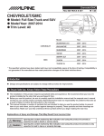
1
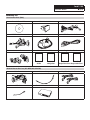
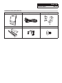
Ford F-150 FULL SIZE TRUCK 1/12 FORD F-150 X009-FD1 9” Installation Manual Model: Full Size Truck Model Year: 2009–2014 Model Year XL STX FORD XLT FX2 FX4 2009 - 2014 Not compatible with 4.2” LCD screen (My Ford), 8” LCD touch screen (My Ford Touch), or factory navigation equipped vehicles. SVT RAPTOR * The specified vehicles have been tested and have met compatibility specs at the time of testing. Compatibility is not guaranteed if the manufacturer has made production changes to the listed vehicles above. Introduction Design and specifications are subject to change without notice for improvement. To Ensure Safe Use, Always Follow These Precautions The installation of this product requires specialized skills and experience. We recommend that you have the product installed by the store that you purchased it from. Before you use this product, be sure to carefully read this installation manual and the separate user's manual so that you can use the product correctly. Alpine Electronics bears no responsibility for problems that arise as a result of failure to follow the instructions in the manuals. This manual includes a number of symbols that are intended to help you use the product safely, to prevent harm to you and others, and to protect against damage to property. These symbols and their meanings are listed below. Make sure you fully understand these symbols before you begin reading the main text. Explanations of Injury and Damage That May Result from Incorrect Use Warning Ignoring the content marked by this indication and using the product incorrectly is expected to lead to death or serious injury. Caution Ignoring the content marked by this indication and using the product incorrectly is only expected to lead to injury or property damage. Ford F-150 FULL SIZE TRUCK Types of Precautions Forbidden Forbidden Indicates actions that are forbidden (must not be performed) Mandatory Indicates that disassembly is forbidden. 2/12 Indicates actions that are mandatory (must be performed) Marks content that should receive your full attention. Warning Do not disassemble or modify the product. Doing so could lead to an accident, fire, or electric shock. Forbidden Store screws and other small objects where small children cannot reach them. If one of these small objects is swallowed, consult with a doctor immediately. When replacing fuses, be sure to use fuses with the specified current rating. Failing to do so could lead to an accident or fire. Forbidden Mandatory Only connect the product to a 12 VDC negative ground car. Failing to do so could lead to an accident or fire. Mandatory Before you begin wiring, remove the ground wire from the negative terminal of the battery. Failing to do so could lead to electric shock or injury. Do not cut the insulation on a cord and take power from another device. Doing so could lead to fire or electric shock. Forbidden Do not install the product in a location where it will obstruct the driver’s forward view; interfere with the operation of the steering wheel, gearshift, or the like; or pose a threat to passengers. Doing so could lead to an accident or injury. Forbidden Ford F-150 FULL SIZE TRUCK 3/12 When making a hole in the vehicle body, be careful to avoid damaging pipes, the fuel tank, electrical wiring, and the like. This kind of damage could lead to an accident or fire. When installing and grounding the product, do not use any of the bolts or nuts of the steering wheel, brakes, fuel tank, or the like. Doing so could make the brakes stop working or lead to fire. Forbidden Do not install the product near the passenger-side airbag. Doing so could interfere with the operation of the airbag and lead to an accident or injury. Forbidden Bundle cords so that they don’t interfere with driving. Wrapping cords around the steering wheel, gearshift, brake pedal, or the like, could lead to an accident or damage equipment. Caution Connect the product properly according to the instructions. Failing to do so could lead to fire or an accident. Forbidden Do not sandwich cords between the seat railing or allow them to touch protrusions. Resulting breaks or shorts could lead to electric shock or fire. Do not block vents or heat sinks. Doing so could lead to fire or damage equipment. Use the accessories according to the instructions, and attach them securely. Failing to do so could lead to an accident or damage equipment. Forbidden Do not install the product where it may be exposed to water or in a place with high levels of humidity or dust. Doing so could lead to fire or damage equipment. Forbidden The installation and wiring of this product requires specialized skills and experience. Have the product installed and wired by the store that you purchased it from. Ford F-150 FULL SIZE TRUCK 4/12 Accessory List Head Unit Box Parts (X009) Owner’s Manual Disc X009 Head Unit X009 Camera Harness AUX/Pre Out Harness GPS Antenna USB Extension Cable 8mm x 8 Screws Quick Reference Guides Registration Cards QRG Audio QRG Navigation Alpine NAVTEQ Registration Card Registration Card iDatalink Maestro Box Parts (ALP-MRR/ALP-HRN-FD1) Main Harness Antenna Adapter USB Cable iDatalink Maestro Module Amplifier Adapter Harness Ford F-150 FULL SIZE TRUCK Installation Kit Parts (G-KTX-009-F150) Headunit Bezel Key harness Mounting Brackets Key Module Microphone 5mm Screw x 2 5/12 Ford F-150 FULL SIZE TRUCK 6/12 X009-FD1 System Wiring To ODB II Connector See Page 9 #5 in detail To Vehicle Connectors Gray Front Red White Purple Red Rear Red Green Red White Sub Main Harness White If factory amplifier is equipped, connect adapter harness on vehicle side Center/Sub2 In White White Red Aux in Red White 4-pin Data Connector 3-pin Black Connector 10-pin Green Connector 3.5 mm Mini plug White iDatalink MAESTRO Module Sub In Aux In 18-pin Black Connector 10-pin Black Connector To SYNC Harness USB Extension Cable GPS Antenna HDMI Input Aux/Pre-out Harness X009 Head Unit To SXM X009-FD1 Key Panel X009 Power Harness Blue Power Antenna (Not used) Blue/White Amp Turn-on Use only with aftermarket amplifiers Green/ White X009 Camera Harness Camera Input Speed Pulse 4-pin Data Connector 3.5 Mini plug Ford F-150 FULL SIZE TRUCK 7/12 Factory unit disassembly process 1 In the passenger side of the vehicle open the glove box and push the side tabs towards inside to release the glove box. Extract 3 X 8 mm (may also be 3 x 10 mm) bolts to release the airbag. 2 Without disconnecting the Airbag push it out far enough to expose the copper plated 7 mm screw on the left side of the airbag and extract it. 3 Remove the instrument cluster panel by extracting 2 x 7 mm screws. 4 Remove both side vent covers by unclipping them using a panel remover tool. 5 Remove cover below HVAC and extract 7 mm screw. 6 At the top of the radio bezel remove the rubber screw cover, extract 2 x 7 mm screws and remove the radio bezel. 7 Extract 4 x 7 mm screws from the factory radio and remove it. Ford F-150 FULL SIZE TRUCK 8/12 Programming the iDatalink Maestro Module 1 INSTALL THE WEBLINK PLUG-IN Go to: idatalinkmaestro.com/plugin and follow the installation steps. 3 CONNECT YOUR MAESTRO MODULE Use the included USB cable to connect your Maestro module to your PC. Review the System Requirements before installing. 4 LOG INTO WEBLINK If the plugin is already installed, the caution, “The plugin is already installed” appears. Please skip to step 2. 2 Go to: idatalinkmaestro.com/login. Enter your username and password, then click OK. REGISTER A WEBLINK ACCOUNT Go to: idatalinkmaestro.com/register and complete the registration process. A confirmation email will be sent to you requiring validation. For existing customers, click log in. 5 PROGRAM YOUR MODULE Follow the programming steps for your vehicle. For existing customers, click log in. 6 COMPLETE INSTALLATION Proceed to the next page to complete installation. Ford F-150 FULL SIZE TRUCK 9/12 Installation Instructions 1 Attach the Maestro module to the X009 main harness. 2 Using an air Reciprocating Saw trim the marked gray area above the headunit. (This will allow the headunit to sit at the adequate height) 3 Connect the factory harness to the main harness and secure it. 4 Remove rubber screw cover from the center dash plate and extract 2 x 7 mm screws. Place GPS antenna as illustrated and feed the cable down to the X009. This is where Sync module and the SW2 wire are located. Can bus wires can also be found at the Sync module. (see step 5 for color code) 5 Access the ODBII connector located under the driver side dashboard. Connect the YELLOW/BROWN wire from the Alpine harness to the WHITE wire located at pin 14 of the OBDII connector. Connect the RED/ BROWN wire from the Alpine harness to the WHITE/ BLUE wire located at pin 6 of the OBDII connector. Connect the PINK/RED wire to the BLUE/ORANGE wire at the SYNC harness on the top center dash under the tray. NOTE: On 2011 thru 2014 models, connection of PINK/RED wire is not required. PINK/RED SWI 2 (-) INPUT SYNC HARNESS STEERING WHEEL SIDE INSULATE WIRE SYNC MODULE SIDE FACTORY RADIO HARNESS WIRES FROM VEHICLE Only use if vehicle is equipped with a factory subwoofer and harness was plugged into the OEM headunit. YELLOW/BROWN -CAN2L RED/BROWN - CAN2H WHITE WHITE/BLUE Ford F-150 FULL SIZE TRUCK Exploded-View Diagram Parts assembly diagram for the X009-FD1 kit. Factory dash bezel Left bracket X009 AVN Unit Headunit Bezel Key Module Right bracket Factory HVAC Panel (not supplied) Bracket Assembly Procedure Attach left & right bracket and key module to the X009 unit using supplied eight M5x8 and two M5x5 screws M5x8 X009 AVN Unit Left bracket M5x5 Right bracket 10/12 Ford F-150 FULL SIZE TRUCK Wiring Installation Procedure 1 Plug in the key connection harness with the “external key unit” label to the key unit. Note the pigtail connection for the included Bluetooth microphone. Bluetooth microphone input 11/12 Ford F-150 FULL SIZE TRUCK Install the radio assembly 1 Attach assembly to the vehicle’s dashboard at these 4 points using the provided screws. 2 Install the HVAC control and Hazard light switch on to the G-KTX-009-F150 panel. 12/12