1
Gigabit Ethernet
Fiber ExpressCard
Module
AT-2872SX
Installation and User’s Guide
613-001261 Rev. A
Copyright © 2010 Allied Telesis, Inc.
All rights reserved. No part of this publication may be reproduced without prior written permission from Allied Telesis, Inc.
Allied Telesis and the Allied Telesis logo are trademarks of Allied Telesis, Incorporated. All other product names, company
names, logos or other designations mentioned herein are trademarks or registered trademarks of their respective owners
Electrical Safety and Emissions Standards
This product meets the following standards.
U.S. Federal Communications Commission
Declaration of Conformity
Manufacturer Name: Allied Telesis, Inc.
Declares that the product: Gigabit Ethernet Fiber ExpressCard Module
Model Numbers: AT-2872SX
This product complies with FCC Part 15B, Class B Limits:
This device complies with part 15 of the FCC Rules. Operation is subject to the following two conditions: (1) This device
must not cause harmful interference, and (2) this device must accept any interference received, including interference
that may cause undesired operation.
Radiated Energy
Note: This equipment has been tested and found to comply with the limits for a Class B digital device pursuant to Part 15
of FCC Rules. These limits are designed to provide reasonable protection against harmful interference in a residential
installation. This equipment generates, uses and can radiate radio frequency energy and, if not installed and used in
accordance with instructions, may cause harmful interference to radio or television reception, which can be determined
by turning the equipment off and on. The user is encouraged to try to correct the interference by one or more of the
following measures:
-
Reorient or relocate the receiving antenna.
-
Increase the separation between the equipment and the receiver.
-
Connect the equipment into an outlet on a circuit different from that to which the receiver is connected.
-
Consult the dealer or an experienced radio/TV technician for help.
Changes and modifications not expressly approved by the manufacturer or registrant of this equipment can void your
authority to operate this equipment under Federal Communications Commission rules.
Industry Canada
This Class B digital apparatus complies with Canadian ICES-003.
Cet appareil numérique de la classe B est conforme à la norme NMB-003 du Canada.
European Union Restriction of the Use of Certain Hazardous Substances
(RoHS) in Electrical and Electronic Equipment
This Allied Telesis RoHS-compliant product conforms to the European Union Restriction of the Use of Certain Hazardous
Substances (RoHS) in Electrical and Electronic Equipment. Allied Telesis ensures RoHS conformance by requiring
supplier Declarations of Conformity, monitoring incoming materials, and maintaining manufacturing process controls.
RFI Emissions
FCC Class B, EN55022 Class B, VCCI Class B, C-TICK, CE
Immunity
EN55024
Electrical Safety
EN60950-1 (TUV), UL 60950-1 (CULUS)
Laser Safety
EN60825
3
Translated Safety Statements
Important: The symbol indicates that a translation of the safety statement is available in a PDF
document titled “Translated Safety Statements”. This is posted on the Allied Telesis website at
http://www.alliedtelesis.com/support/software/. Refer to “Where to Find Web-based
Documentation and Drivers” on page 13 to navigate to this document.
4
Contents
Preface ................................................................................................................................................................................ 11
Safety Symbols Used in this Document................................................................................................................................12
Where to Find Web-based Documentation and Drivers .......................................................................................................13
Contacting Allied Telesis ......................................................................................................................................................14
Online Support ..............................................................................................................................................................14
Email and Telephone Support .......................................................................................................................................14
Warranty ........................................................................................................................................................................14
Returning Products........................................................................................................................................................14
Sales or Corporate Information .....................................................................................................................................14
Warranty ........................................................................................................................................................................14
Management Software Updates ....................................................................................................................................14
Chapter 1: Introducing the AT-2872SX Gigabit Ethernet Fiber ExpressCard Module ................................................ 15
Functional Description ..........................................................................................................................................................16
Contents of Your Shipment ...........................................................................................................................................16
Hardware Features ...............................................................................................................................................................18
Supported Operating Systems .............................................................................................................................................19
Physical Description .............................................................................................................................................................20
Chapter 2: Installing the Hardware .................................................................................................................................. 21
Reviewing Safety Precautions ..............................................................................................................................................22
Pre-Installation Checklist ......................................................................................................................................................24
Installing the Module.............................................................................................................................................................25
Connecting the Network Cables ...........................................................................................................................................30
Chapter 3: Installing the Windows Drivers...................................................................................................................... 33
Installing the Windows Driver Software ................................................................................................................................34
Using the Installer..........................................................................................................................................................35
Using Silent Installation .................................................................................................................................................39
Removing the Device Drivers ...............................................................................................................................................42
Windows XP ..................................................................................................................................................................42
Vista and Windows 7 .....................................................................................................................................................42
Using the NetXtreme II Monolithic Driver..............................................................................................................................43
Inserting the NetXtreme II Monolithic Driver in a WinPE 2.0 Image .....................................................................................45
Configuring the Speed and Duplex Settings .................................................................................................................46
Displaying or Changing the Properties of the Adapter..........................................................................................................48
Chapter 4: Installing the Linux Drivers............................................................................................................................ 49
Introduction ...........................................................................................................................................................................50
Limitations .....................................................................................................................................................................50
Packaging......................................................................................................................................................................51
Installing Linux Driver Software ............................................................................................................................................52
Installing the Source RPM Package ..............................................................................................................................52
Building the Driver from the Source TAR File................................................................................................................54
Load and Run Necessary iSCSI Software Components ...............................................................................................56
Unloading the Linux Driver ............................................................................................................................................56
Patching PCI Files (Optional) ........................................................................................................................................57
Network Installations .....................................................................................................................................................58
Setting Values for Optional Properties ..........................................................................................................................58
Checking the bnx2 Driver Defaults ................................................................................................................................61
Checking Driver Messages............................................................................................................................................62
Teaming with Channel Bonding ....................................................................................................................................66
Statistics ........................................................................................................................................................................66
Linux iSCSI Offload .......................................................................................................................................................66
5
Contents
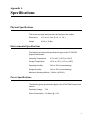
Appendix A: Specifications .............................................................................................................................................. 71
Physical Specifications .........................................................................................................................................................71
Environmental Specifications................................................................................................................................................71
Power Specifications.............................................................................................................................................................71
Performance Specification ....................................................................................................................................................72
Operating Specifications .......................................................................................................................................................72
Appendix B: Cleaning Fiber Optic Connectors............................................................................................................... 73
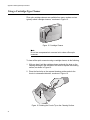
Using a Cartridge-Type Cleaner ...........................................................................................................................................74
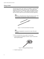
Using a Swab........................................................................................................................................................................76
6
Figures
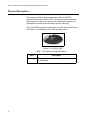
Figure 1. AT-2872SX ExpressCard module ........................................................................................................................16
Figure 2. AT-2872SX LED ...................................................................................................................................................20
Figure 3. Selecting the ExpressCard Slot............................................................................................................................26
Figure 4. Pressing the Button ..............................................................................................................................................27
Figure 5. Removing the Faceplate From PCI ExpressCard Slot .........................................................................................27
Figure 6. Removing the Plate ..............................................................................................................................................28
Figure 7. Inserting the Module .............................................................................................................................................29
Figure 8. Found New Hardware Wizard Page .....................................................................................................................35
Figure 9. Broadcom NetXtreme II Driver Installer - InstallShield Wizard Page....................................................................36
Figure 10. License Agreement Page ...................................................................................................................................37
Figure 11. Ready to Install the Program Page.....................................................................................................................38
Figure 12. InstallShield Wizard Completed Page ................................................................................................................39
Figure 13. Ferrule in an SC Connector Plug........................................................................................................................73
Figure 14. Unclean and Clean Ferrule.................................................................................................................................73
Figure 15. Cartridge Cleaner ...............................................................................................................................................74
Figure 16. Rubbing the Ferrule Tip on the Cleaning Surface ..............................................................................................74
Figure 17. Lint-Free and Alcohol-Free Swabs .....................................................................................................................76
Figure 18. Cleaning a Recessed Ferrule .............................................................................................................................76
7
Figures
8
Tables
Table 1: Safety Symbols ......................................................................................................................................................12
Table 2: Fiber Optic Port 1000 LED Status .........................................................................................................................20
Table 3: Broadcom NetXtreme II Linux Drivers ...................................................................................................................50
Table 4: Linux Driver Packaging ..........................................................................................................................................51
9
Tables
10
Preface
This guide contains instructions on how to install the AT-2872SX Gigabit
Ethernet Fiber ExpressCard Module on a laptop computer. It also
describes how to install the driver software on the AT-2872SX
ExpressCard module and configure the driver software. The driver
software is supported on the following operating systems:
Windows XPTM
Windows VistaTM
Windows 7TM
The Preface contains the following sections:
“Safety Symbols Used in this Document” on page 12
“Where to Find Web-based Documentation and Drivers” on page 13
“Contacting Allied Telesis” on page 14
11
Preface
Safety Symbols Used in this Document
This document uses the safety symbols defined in Table 1.
Table 1. Safety Symbols
Symbol
12
Meaning
Description
Caution
Performing or omitting a specific action may
result in equipment damage or loss of data.
Warning
Performing or omitting a specific action may
result in electrical shock.
AT-2872 SX Gigabit Ethernet Fiber ExpressCardTM Interface User’s Guide
Where to Find Web-based Documentation and Drivers
The product documentation for all Allied Telesis products are available in
portable document format (PDF) on our web site. Go to
http://www.alliedtelesis.com/support/software/.
Enter your hardware product model in the Search by Product Name
field; for example, enter AT-2872SX. You can view the documents online
or download them onto your local workstation or server.
13
Preface
Contacting Allied Telesis
This section provides Allied Telesis contact information for technical
support as well as sales and corporate information.
Online Support
You can request technical support online by accessing the Allied Telesis
Knowledge Base: www.alliedtelesis.com/support/kb.aspx. You can use
the Knowledge Base to submit questions to our technical support staff and
review answers to previously asked questions.
Email and
Telephone
Support
For Technical Support via email or telephone, refer to the Support &
Services section of the Allied Telesis web site: www.alliedtelesis.com.
Select your country from the list displayed on the website. then select the
appropriate menu tab.
Warranty
For hardware warranty information, refer to the Allied Telesis web site:
www.alliedtelesis.com/support/warranty.
Returning
Products
Products for return or repair must first be assigned a return materials
authorization (RMA) number. A product sent to Allied Telesis without an
RMA number will be returned to the sender at the sender’s expense.
To obtain an RMA number, contact the Allied Telesis Technical Support
group at our web site: www.alliedtelesis.com/support/rma. Select your
country from the list displayed on the website. Then select the appropriate
menu tab.
Sales or
Corporate
Information
Warranty
Management
Software Updates
You can contact Allied Telesis for sales or corporate information through
our web site: www.alliedtelesis.com. To find the contact information for
your country, select Contact Us -> Worldwide Contacts.
Go to www.alliedtelesis.com/support/warranty for specific terms and
conditions of the warranty and for warranty registration for the
AT-2872SX Gigabit Ethernet Fiber ExpressCard Module.
New releases of management software for our managed products are
available on our Allied Telesis web site at
www.alliedtelesis.com/support/software.
Go to “Where to Find Web-based Documentation and Drivers” on page 13
for instructions on navigating to this information.
14
Chapter 1
Introducing the AT-2872SX Gigabit
Ethernet Fiber ExpressCard Module
This chapter provides an introduction to the Allied Telesis AT-2872SX
Gigabit Ethernet Fiber ExpressCard Module and contains the following
sections:
“Functional Description” on page 16
“Hardware Features” on page 18
“Supported Operating Systems” on page 19
“Physical Description” on page 20
15
Chapter 1: Introducing the AT-2872SX Gigabit Ethernet Fiber ExpressCard Module
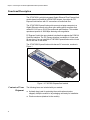
Functional Description
The AT-2872SX is a highly integrated Gigabit Ethernet Fiber ExpressCard
module based on Broadcom’s BCM5708S chipset. It provides an PCI
ExpressCard interface with SC connections to multimode fiber.
The AT-2872SX ExpressCard module connects a laptop computer to a
Gigabit Ethernet network using fiber optic cabling and a connector that
meets 62.5/125 µm or 50/125 µm multimode specifications. This module
operates at speeds of 1000 Mbps featuring auto-negotiation.
PC Express Card is the new notebook interface that replaces the PCMCIA
Card Bus interface. The PC Express interface is available in 34 mm and
54 mm sizes. You can install the AT-2872SX ExpressCard module in both
the 34 mm and 54 mm sizes.
LI
N
K/
AC
T
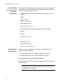
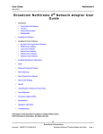
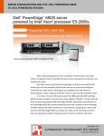
The AT-2872SX ExpressCard module has an SC connector, as show in
Figure 1.
1757
1929
Figure 1. AT-2872SX ExpressCard module
Contents of Your
Shipment
16
The following items are included with your module:
Antistatic bag (used for protecting the module when stored or
shipped). Keep the module in its packaging until ready for installation.
Plastic enclosure (attached to the module)
AT-2872SX ExpressCard Fast Ethernet Fiber Module Installation and User’s Guide
Note
The AT-2872SX ExpressCard module is not shipped with a software
driver CD. To download new driver software, see “Management
Software Updates” on page 14.
Inform your network supplier of any missing or damaged items. If you need
to return the module, you must pack it in the original (or equivalent)
packing material or the warranty will be voided. See “Returning Products”
on page 14.
The documentation for this module is available in portable document
format (PDF) on our web site at www.alliedtelesis.com. To information to
view or download these documents, refer to “Where to Find Web-based
Documentation and Drivers” on page 13.
17
Chapter 1: Introducing the AT-2872SX Gigabit Ethernet Fiber ExpressCard Module
Hardware Features
The following list of hardware features for the AT-2872SX ExpressCard
module applies to all of the supported operating systems:
18
One 1000BASE-SX port with SC multi-mode fiber connector
Full and half duplex Media Access Control (MAC)
IPv4 Large Send Offload and Checksum Offload (LSO/TCO)
Receive Side Scaling (RSS) for multi-core client processors
PCI-ExpressCard Interface
Statistics for SNMP MIB II, Ethernet-like MIB, and Ethernet MIB (802.3z Clause 30)
Flow Control (IEEE 802.3x)
VLAN Tag support (802.1Q)
Ethernet Priority (802.1P)
Pre-boot Execution Environment (PXE) v2.1
Jumbo Packet Support
48 KB Receive Buffer
8 KB Transmit Buffer
Activity LED
Interrupt Moderation
AT-2872SX ExpressCard Fast Ethernet Fiber Module Installation and User’s Guide
Supported Operating Systems
The following list describes the supported operating systems for the
AT-2872SX ExpressCard module:
Windows XP
Windows Vista
Windows 7
19
Chapter 1: Introducing the AT-2872SX Gigabit Ethernet Fiber ExpressCard Module
Physical Description
This section provides a physical description of the AT-2872SX
ExpressCard enclosure and the LED. The enclosure has one fiber port
that provides two fiber optic connectors for attaching the module to a
compatible link partner (one transmitting and one receiving).
LI
N
K/
AC
T
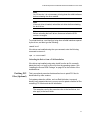
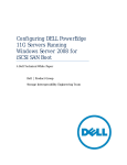
The AT-2872SX ExpressCard module has one LED, as shown in Figure 2.
See Table 1 for a description of the LED operating status.
1757
Figure 2. AT-2872SX LED
Table 1. Fiber Optic Port 1000 LED Status
State
Flashing
20
Description
The port is receiving or transmitting network packets
at 1000 Mbps.
Chapter 2
Installing the Hardware
This chapter contains the following sections:
“Reviewing Safety Precautions” on page 22
“Pre-Installation Checklist” on page 24
“Installing the Module” on page 25
“Connecting the Network Cables” on page 30
21
Chapter 2: Installing the Hardware
Reviewing Safety Precautions
Please review the following safety precautions before you begin to install
the switch or any of its components. The indicates that a translation of
the safety statements is available in a PDF document titled “Translated
Safety Statements”. This other product documentation is posted on the
Allied Telesis website at http://www.alliedtelesis.com/support/
software/. Refer to “Where to Find Web-based Documentation and
Drivers” on page 13 to navigate to this document.
Warning
This is a “Class 1 LED product”. L1
Warning
Do not stare into the laser beam. L2
Warning
The fiber optic ports contain a Class 1 laser device. When the ports
are disconnected, always cover them with the provided plug.
Exposed ports may cause skin or eye damage. L4
Warning
Do not work on this equipment or cables during periods of lightning
activity. E2
Warning
Operating Temperature: This product is designed for a maximum
ambient temperature of 40 degrees C. E7
Warning
All Countries: Install this product in accordance with local and
National Electric Codes. E8
Warning
Do not look directly at the fiber optic cable ends or inspect the cable
ends with an optical lens. E29
22
AT-2872SX ExpressCard Fast Ethernet Fiber Module Installation and User’s Guide
Warning
The adapter is being installed in a system that operates with
voltages that can be lethal. Before you remove the cover of your
system, you must observe the following precautions to protect
yourself and to prevent damage to the system components:
- Remove any metallic objects or jewelry from your hands and wrists.
- Use only insulated and non-conducting tools.
- Verify that the system is powered off and unplugged before
accessing the internal components.
- Installation or removal of adapters must be performed in a staticfree environment. The use of a properly grounded wrist strap or
other personal antistatic device and an antistatic mat is strongly
recommended. E39
Caution
Do not use excessive force when seating the module, because this
may damage the system or the module. If the module resists
seating, remove it from the system, realign it, and try again
23
Chapter 2: Installing the Hardware
Pre-Installation Checklist
Before you install the module, check the following list:
1. Verify that your laptop is using the latest BIOS.
If you downloaded the module software from the Allied Telesis support
website, record the path to where the module driver files reside on
your system.
2. If your laptop is active, shut it down.
3. When the system shut down is complete, power OFF and unplug your
system.
4. Holding the module by the edges, remove it from its shipping package
and place it on an antistatic surface.
5. Check the module for visible signs of damage, particularly on the edge
connector.
Caution
Do not attempt to install a damaged module. If the module is
damaged, report it to Allied Telesis. See “Contacting Allied Telesis”
on page 14.
24
AT-2872SX ExpressCard Fast Ethernet Fiber Module Installation and User’s Guide
Installing the Module
The following instructions describe how to install the AT-2872SX
ExpressCard module in a laptop equipped with an ExpressCard interface
slot. This procedure applies to laptops with either 34 mm or 54 mm
interface slots. For laptop computers, the 54 mm interface is the more
common interface. Therefore, the installation illustrations in this manual
use the 54 mm interface.
For additional details about performing these tasks on your particular PC,
refer to the manual that was supplied with your laptop.
Note
Allied Telesis recommends that you turn off your PC before installing
the AT-2872SX ExpressCard module.
Note
To perform this procedure, you need to supply a pen.
To install an AT-2872SX ExpressCard module, perform the following
procedure:
1. Review the “Pre-Installation Checklist” on page 24 and “Reviewing
Safety Precautions” on page 22.
Before installing the module, ensure the laptop power is OFF and
unplugged from the power outlet.
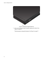
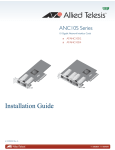
2. Select the 34 mm or 54 mm ExpressCard slot.
See Figure 3 on page 26 for an example of the 54 mm ExpressCard
slot.
Note
If you do not know how to identify an ExpressCard slot, refer to your
laptop documentation.
25
Chapter 2: Installing the Hardware
1758
Figure 3. Selecting the ExpressCard Slot
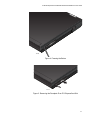
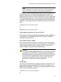
3. Use a pen and press the button toward the laptop and to the left. See
Figure 4 on page 27.
The button pops out along with the plate. See Figure 5 on page 27.
26
AT-2872SX ExpressCard Fast Ethernet Fiber Module Installation and User’s Guide
1710
Figure 4. Pressing the Button
1711
Figure 5. Removing the Faceplate From PCI ExpressCard Slot
27
Chapter 2: Installing the Hardware
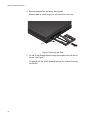
4. Remove the plate from the laptop. See Figure 6.
Keep the plate in a safe place. You may need it for future use.
1712
Figure 6. Removing the Plate
5. For the 54 mm ExpressCard slot, align the module to the left side of
the slot. See Figure 7.
For laptops with the 34 mm ExpressCard slot, the module fits snugly
into the slot.
28
AT-2872SX ExpressCard Fast Ethernet Fiber Module Installation and User’s Guide
LLI
NIN
KK/
A/AC
CT
T
6. Applying even pressure at both corners of the module, push the
module until it is firmly seated in the ExpressCard slot. See Figure 7.
1757
1930
Figure 7. Inserting the Module
7. Make sure the module is seated securely.
8. Power the system on.
Once the system returns to proper operation, the module hardware is
fully installed. Next, connect the network cables. See “Connecting the
Network Cables” on page 30.
29
Chapter 2: Installing the Hardware
Connecting the Network Cables
The AT-2872SX ExpressCard module has two fiber optic connectors
(transmit and receive) for attaching the system to a compatible link
partner, or an IEEE 802.3z compliant Gigabit Ethernet switch.
The module requires a fiber optic cable. For specifications for this cable,
see the AT-2872SX ExpressCard module data sheet.
After you install the cables, see the appropriate chapter for software driver
installation and configuration information. See one of the following
chapters:
Chapter 3, “Installing the Windows Drivers” on page 33
Chapter 4, “Installing the Linux Drivers” on page 49
To connect a network cable to the module, do the following:
1. Connect one end of the cable to the module.
2. Connect the other end of the cable to the appropriate Ethernet fiber
optic port.
After you connect the system to the network and power is supplied, the
AT-2872SX ExpressCard module attempts to establish the connection
at 1000 Mbps in auto-negotiation mode.
Note
Since the port on the AT-2872SX ExpressCard module operates in
auto-negotiate mode only, the end nodes connected to the AT2872SX ExpressCard module must also be configured to operate in
the Auto-Negotiate mode. If an end node is configured to a specific
duplex in a manual mode, it will not respond to the Auto-Negotiate
protocol from the AT-2872SX ExpressCard module. (The speed is
determined from the link pulses, however, so the speed is always
detected correctly.) As a result, the port setting on the AT-2872SX
ExpressCard module will end up at half-duplex. If the end node is
manually configured to full-duplex, there will be a duplex mismatch
and data will be lost. If the end node is manually configured to halfduplex, both ports will have the speed and duplex match up
correctly. Refer to “Configuring the Speed and Duplex Settings” on
page 46 for more information.
Note
After the cable is properly connected at both ends, the module port
LED is functional. See “Physical Description” on page 20 for a
description of the LED operation.
30
AT-2872SX ExpressCard Fast Ethernet Fiber Module Installation and User’s Guide
Note
For instructions that describe how to clean the fiber optic connector,
see Appendix B “Cleaning Fiber Optic Connectors” on page 73
31
Chapter 2: Installing the Hardware
32
Chapter 3
Installing the Windows Drivers
This chapter provides procedures to install and remove the driver software
for all of the Windows Operating Systems supported by the AT-2872SX
ExpressCard module. In addition, it describes how to display and change
adapter properties including power management options. This chapter
covers the following topics:
“Installing the Windows Driver Software” on page 34
“Removing the Device Drivers” on page 42
“Using the NetXtreme II Monolithic Driver” on page 43
“Inserting the NetXtreme II Monolithic Driver in a WinPE 2.0 Image” on
page 45
“Displaying or Changing the Properties of the Adapter” on page 48
33
Chapter 3: Installing the Windows Drivers
Installing the Windows Driver Software
This chapter describes how to install all of the following Windows
Operating Systems:
Microsoft Windows XP (32-bit and 64-bit extended)
Microsoft Windows Vista (32-bit and 64-bit extended)
Microsoft Windows 7 (32-bit and 64-bit extended)
The Windows driver software for all of the Windows Operating Systems is
available for download from the Allied Telesis website at:
www.alliedtelesis.com. To navigate to this document, refer to “Where to
Find Web-based Documentation and Drivers” on page 13 for more
information.
Note
Windows 7 may install an older version of the AT-2872SX driver.
Allied Telesis recommends that you use the latest version of the
driver available on our Allied Telesis website. To find this driver, refer
to “Where to Find Web-based Documentation and Drivers” on
page 13 for more information.
When Windows first starts after a hardware device such as an AT-2872SX
ExpressCard module has been installed, or after the existing device driver
has been removed, the operating system automatically detects the
hardware and prompts you to install the driver software for that device.
The two methods used to install the software drivers on all of the Windows
Operating Systems supported by the AT-2872SX ExpressCard module
are the Installer and Silent installation. The Installer uses a graphical
interactive mode. The Silent Installation is a command-line interface for
unattended installation. See the following sections:
“Using the Installer” on page 35
“Using Silent Installation” on page 39
Note
These instructions are based on the assumption that your adapter
was not factory installed. If your controller was installed at the
factory, the driver software has been installed for you.
Note
Before installing the driver software, verify that the Windows
operating system has been upgraded to the latest version with the
latest service pack applied.
34
AT-2872SX ExpressCard Fast Ethernet Fiber Module Installation and User’s Guide
Note
A network device driver must be physically installed before the
Broadcom NetXtreme II Controller can be used with your Windows
operating system. There is no installation CD. You must download
the drivers.
Note
Allied Telesis recommends that you not perform hot insertions or hot
removal when the OS is up and running, We recommend that you
insert or remover the adapter only when the system is powered
down.
Using the
Installer
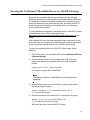
The Installer is a graphical interactive installation mode. To install the AT2872SX driver on a Windows Operating System, do the following:
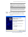
1. When the Found New Hardware Wizard appears, click Cancel.
See Figure 8.
Figure 8. Found New Hardware Wizard Page
35
Chapter 3: Installing the Windows Drivers
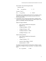
2. From the driver directory, select the setup.exe file and Run.
The Broadcom NetXtreme II Driver Installer - InstallShield Wizard
Page is displayed. See Figure 9 on page 36.
Note
There is a setup.exe file for the 32-bit operating system and another
for the 64-bit operating system. You can use each installer on Win
XP, Vista, and Windows 7.
Figure 9. Broadcom NetXtreme II Driver Installer - InstallShield Wizard
Page
3. Click Next to continue.
The License Agreement Page is displayed. See Figure 10 on page 37.
36
AT-2872SX ExpressCard Fast Ethernet Fiber Module Installation and User’s Guide
Figure 10. License Agreement Page
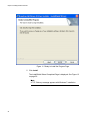
4. After you review the license agreement, click I accept the terms in
the license agreement and then click Next to continue.
The Ready to Install the Program Page is displayed. See Figure 11 on
page 38.
37
Chapter 3: Installing the Windows Drivers
Figure 11. Ready to Install the Program Page
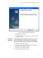
5. Click Install.
The InstallShield Wizard Completed Page is displayed. See Figure 12
on page 39.
Note
A TCP Chimney message appears with Windows 7 installation.
38
AT-2872SX ExpressCard Fast Ethernet Fiber Module Installation and User’s Guide
Figure 12. InstallShield Wizard Completed Page
6. Click Finish to close the wizard.
7. The installer determines if a system restart is necessary. Follow the
on-screen instructions.
Using Silent
Installation
Silent installation provides a command-line silent mode which allows for
unattended installation. This section discusses the various ways to
perform a silent installation on all of the Windows Operating Systems
supported by the AT-2872SX ExpressCard module. See the following:
“Performing a Silent Install” on page 40
“Performing a Silent Install and Creating a Log File” on page 40
“Performing a Silent Upgrade” on page 40
“Performing a Silent Uninstall” on page 40
“Performing a Silent Reinstall” on page 41
39
Chapter 3: Installing the Windows Drivers
Note
All commands are case sensitive.
Note
User must “Run as Administrator” for Vista when using “msiexec” for
“silent” install or uninstall procedures.
Note
For detailed instructions and information about unattended installs,
refer to the Silent.txt file in the DrvInst folder.
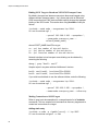
Performing a Silent Install
To perform a silent install from within the installer source folder, type the
following:
setup /s /v/qn
or
msiexec /i “BDrv5706.msi” /qn
Performing a Silent Install and Creating a Log File
To perform a silent install and create a log file at (f:\1testlog.txt), type the
following:
setup /s /v”/qn /L f:\1testlog.txt”
Performing a Silent Upgrade
To perform a silent upgrade from within the installer source folder, type the
following:
setup /s /v/qn
Performing a Silent Uninstall
There are two ways to perform a silent uninstall— from the installer source
folder and from the any folder.
In some circumstances, you must reboot your system before uninstallation
can continue. If you used REBOOT=ReallySuppress to suppress the
reboot, the uninstallation may be suspended. You will need to reboot
manually for the uninstallation to continue.
40
AT-2872SX ExpressCard Fast Ethernet Fiber Module Installation and User’s Guide
To perform a silent uninstall from within the installer source folder, type the
following:
msiexec /x “BDrv5706.msi” /qn
To perform a silent uninstall from any folder, type the following:
msiexec /x “{F0DA8A3F-1457-419E-96F4-235DD3EF41E1}” /
qn
Note
The hexidecimal number above may differ from your current
installer. Check the Key name corresponding with the Broadcom
Advanced Control Suite 3 (BACS) application in
HKLM\Software\Mictrosoft\Windows\CurrentVersion\Uninstall for the
correct hexidecimal number.
Performing a Silent Reinstall
To perform a silent reinstall of the same installer, type the following:
setup /s /v”/qn REINSTALL=ALL”
Note
The REINSTALL switch should only be used if the same installer is
already installed on the system. If upgrading an earlier version of the
installer, use setup /s /v/qn as listed above.
41
Chapter 3: Installing the Windows Drivers
Removing the Device Drivers
This section discusses how to remove the device drivers.
Windows XP
To remove the device drivers, do the following:
1. In Control Panel, double-click Add or Remove Programs.
2. Click Broadcom NetXtreme II GigE Driver Installer, and then click
Remove. Follow the on screen prompts.
3. Click Yes to restart your system.
- or 4. Click No to restart your system at a later time. Click OK to
acknowledge that the installation has been suspended. The
uninstallation of the driver is postponed until the next restart of your
system.
Vista and
Windows 7
To remove the device drivers, do the following:
1. Go to Programs and Features
2. Highlight “Broadcom Net Xtreme II Driver Installer”
3. Select “Uninstall” from the top menu.
42
AT-2872SX ExpressCard Fast Ethernet Fiber Module Installation and User’s Guide
Using the NetXtreme II Monolithic Driver
The NetXtreme II, based on its advanced functionalities, uses a software
architecture that includes a Virtual Bus Device (VBD) to extend
functionalities beyond basic network connectivity. Microsoft, however,
does not currently support this architecture when loading an operating
system through its Windows Deployment Services (WDS), which was
previously known as Remote Installation Services (RIS), or for the
deployment agent used in the Automated Deployment Services (ADS).
Therefore, a separate driver was created to accommodate these Microsoft
deficiencies. This driver is known as the NetXtreme II monolithic driver, but
it is sometimes referred to as the RIS driver.
The NetXtreme II monolithic driver was developed to work only for the text
mode portion of a WDS legacy installation and to establish connectivity
with a deployment agent for ADS. It is not intended to be used as a driver
loaded in the running state of an operating system. The exception to this
would be when used for the Windows Preinstallation Environment
(WinPE).
For WDS, this driver is used similarly to any other network adapter driver
for supporting network connectivity after the PXE boot to the WDS server.
When placed in the I386 or AMD64 directory (depending on the version of
the operating system being deployed), the monolithic driver is called to
establish that there is driver support for the NetXtreme II adapter included
in the WDS legacy image.
For ADS, the driver is placed in the PreSystem directory on the server
running ADS to establish connectivity with the deployment agent on
remote systems with NetXtreme II adapters when booting from PXE.
While Windows PE 2005 natively supports the VBD architecture, it was
found that using the “minint” switch in the startnet.cmd file does not. The
minint switch performs a limited scan of the system bus to identify network
devices only and, therefore, does not support the VBD architecture. Since
only network connectivity is required in Windows PE, the only supported
driver is the monolithic driver for the NetXtreme II adapter in this
environment as well. Place the b06nd.inf file in the INF directory within the
Windows PE image, and place the appropriate driver file (b06nd51a.sys
for x64-based builds or b06nd51.sys for x86-based builds) in the driver's
directory. If Windows PE is deployed as a flat image from a RIS or WDS
server, you must also place both the b06nd.inf and the appropriate driver
file in the I386 or AMD64 directory containing the image. If the RIS or WDS
server is running Windows 2000 Server and deploying an x86 WinPE
image, you may need to include the Windows 2000 monolithic driver file
(b06nd50x.sys) in the I386 directory.
43
Chapter 3: Installing the Windows Drivers
In cases where adding the Windows 2000 monolithic driver still does not
work, apply the following modification to the b06nd.inf file located in the
I386 directory as follows:
1. Locate [Manufacturer] header within the file.
2. Review the line below it which reads: %brcm% = broadcom, ntx86,
ntamd64, ntia64 or equivalent.
3. Modify that line to read: %brcm% = broadcom.ntx86, ntamd64, ntia64.
The change made replaces the comma and space after “broadcom”
with a period.
4. Save the file.
5. Restart the RIS service (binlsvc) or WDS services (wdsserver).
44
AT-2872SX ExpressCard Fast Ethernet Fiber Module Installation and User’s Guide
Inserting the NetXtreme II Monolithic Driver in a WinPE 2.0 Image
By default, the monolithic driver is not included in the boot.wim and
install.wim files that come with the Microsoft Windows Server 2008/Vista
CD. Microsoft's Windows Automated Installation Kit (AIK) allows you to
modify the default boot.wim and install.wim files, and create WinPE 2.0
images to include the NetXtreme II monolithic driver in the Windows
Server 2008/Vista installation.
To insert Broadcom's NetXtreme II monolithic driver in a WinPE 2.0 image
(Vista/Windows Server 2008), download AIK from
http://www.microsoft.com/downloads/Search.aspx?displaylang=en and
install.
After installing AIK, copy the latest monolithic driver to a directory on the
local hard drive of the system you installed the AIK. Follow the procedure
below to insert the monolithic driver into a WinPE 2.0 boot image.
To insert the monolithic driver into a WinPE 2.0 boot image, do the
following:
1. From All Programs, open Windows AIK and select Windows PE Tools
Command prompt.
2. At the command prompt, run the copype.cmd script. The script
requires two arguments: hardware architecture and destination
location.
copype.cmd <arch> <destination>
For example: copype x86 c:\VistaPEx86
Note
The directory structure c:\VistaPEx86 is used throughout this
procedure.
3. Mount the base image to a local directory so that you can add or
remove packages by typing:
imagex /mountrw c:\VistaPEx86\winpe.wim 1
c:\VistaPEx86\mount
4. Place the monolithic driver and inf file in c:\drivers\x32\ by typing:
peimg /inf=c:\Drivers\x32\b06nd.inf
c:\VistaPEx86\mount\windows
AIK inserts the driver into the WinPE 2.0 image.
45
Chapter 3: Installing the Windows Drivers
5. To complete the customization of the image, prepare the image for
deployment, type:
peimg /prep c:\VistaPEx86\mount\windows
6. When asked to continue and have the program prepare the image for
deployment, type:
yes
7. To commit the changes to the original image file (Winpe.wim), type:
imagex /unmount c:\VistaPEx86\mount /commit
8. To replace the default Boot.wim file in the \ISO directory with your new
custom image, type:
copy c:\VistaPex86\winpe.wim
c:\VistaPEx86\ISO\sources\boot.wim
Creating a Bootable CD ROM
To create a bootable CD-ROM, do the following:
1. On your technician computer, at the command prompt, create an .iso
file by typing:
oscdimg -n -bc:\VistaPEx86\etfsboot.com
c:\VistaPEx86\ISO C:\VistaPEx86\VistaPEx86.iso
2. Burn the iso image to a CD.
Configuring the
Speed and Duplex
Settings
Since the typical environment where the NetXtreme II monolithic driver is
used does not provide the means to configure advanced network adapter
properties, the driver file (b06nd.inf) was modified to include a section that
allows it to be configured for a specific speed and/or duplex. This provides
a more robust connection to the network as it allows the adapter to match
the settings of its link partner (for example, a switch, router, etc.).
To manually configure the speed and duplex, do the following:
1. Open the b06nd.inf file with a text editor like Microsoft Notepad or
WordPad.
2. Perform a search on the file for “Registry parameters” to locate the
section that will allow you to configure the adapter speed/duplex.
46
AT-2872SX ExpressCard Fast Ethernet Fiber Module Installation and User’s Guide
Once located, notice the following information:
[params_utp]
hkr, , req_medium,
2, “0”
[params_fiber]
hkr, , req_medium,
2, “65283”
These make up two separate sections that can be configured: one for
standard RJ-45 copper interfaces (params_utp) and one for fiber
devices (params_fiber).
3. As described in the file, replace the value above in quotation marks
under the correct section, depending upon the network adapter in your
system. The available values are shown below.
Options for copper interfaces:
–
Auto (1 Gbps is enabled when that speed is
supported) = “0”
–
10 Mbps Half Duplex = “65794”
–
10 Mbps Full Duplex = “258”
–
100 Mbps Half Duplex = “66050”
–
100 Mbps Full Duplex = “514”
Options for fiber interfaces:
–
Auto (1 Gbps is enabled when that speed is
supported) = “0”
–
1 Gbps Full Duplex = “771”
–
Auto with 1 Gbps Fallback = “33539”
–
Hardware default = “65283”
An example is provided in the file showing how to configure a copper
interface for a 10 Mbps Full Duplex connection. The example is shown
below.
–
hkr, , req_medium,
2, “258”
47
Chapter 3: Installing the Windows Drivers
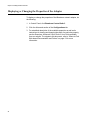
Displaying or Changing the Properties of the Adapter
To display or change the properties of the Broadcom network adapter, do
the following:
1. In Control Panel, click Broadcom Control Suite 3.
2. Click the Advanced section of the Configurations tab.
3. For a detailed description of the available properties as well as for
instructions for viewing and changing the value of a particular property,
see the Broadcom Advanced Control Suite 3 User Guide available
from our website. To navigate to this document, refer to “Where to Find
Web-based Documentation and Drivers” on page 13 for more
information.
48
Chapter 4
Installing the Linux Drivers
This chapter provides procedures to install the Linux drivers for the AT2872SX ExpressCard module
This chapter contains the following topics:
“Introduction” on page 50
“Installing Linux Driver Software” on page 52
49
Chapter 4: Installing the Linux Drivers
Introduction
This chapter discusses the Linux drivers for the Broadcom NetXtreme II
network adapters and describes how to install them. For a description of
the drivers, see Table 2.
Table 2. Broadcom NetXtreme II Linux Drivers
Linux Driver
Limitations
Description
bnx2
cnic
Indicates the Linux drivers for the AT-2872SX
ExpressCard module. The bnx2 driver is the
networking driver and the cnic driver supports
additional features required by the bnx2i iSCSI
offload driver. The bnx2i iSCSI driver is
packaged separately.
bnx2i
Indicates the Linux driver that enables iSCSI
offload on the AT-2872SX ExpressCard
module.
This section describes the testing limitations of the following Linux drivers:
“bnx2 Driver” on page 50
“bnx2i Driver” on page 51
bnx2 Driver
The current version of the driver has been tested on 2.4.x kernels (starting
from 2.4.24) and all 2.6.x kernels. The driver may not compile on kernels
older than 2.4.24.
Testing is concentrated on i386 and x86_64 architectures. Only limited
testing has been done on other architectures. Minor changes to some
source files and Makefile may be needed on some kernels. Additionally,
the Makefile does not compile the cnic driver on kernels older than 2.6.16.
iSCSI offload is only supported on 2.6.16 and newer kernels.
Support for the 2.4.21 kernels is provided in Red Hat Enterprise Linux 3.
50
AT-2872SX ExpressCard Fast Ethernet Fiber Module Installation and User’s Guide
bnx2i Driver
The current version of the driver has been tested on 2.6.x kernels, starting
from 2.6.18 kernel. The driver may not compile on older kernels with the
exception of SLES 10 SP1, which runs 2.6.16.46 kernel. SUSE upgraded
the iscsi_transport kernel module in SLES 10 SP1. In addition, Broadcom
iSCSI offload initiators is supported on SLES 10 SP1. Testing is
concentrated on i386 and x86_64 architectures, Red Hat EL5, and SUSE
10 SP1 distributions.
Packaging
The Linux driver is released in the packaging formats shown in Table 3.
The netxtreme2 package contains the bnx2 (1 Gb network adapter) and
drivers for source RPM and compressed tar.
Table 3. Linux Driver Packaging
Format
bnx2 Driver
bnx2i (iSCSI) Driver
Source RPM
netxtreme2version.src.rpm
bnx2i-version.src.rpm
Compressed tar
netxtreme2version.tar.gz
bnx2i-version.tar.gz
Supplemental tar
netxtreme2_supversion.tar.gz
bnx2i_sup-version.tar.gz
Identical source files to build the driver are included in both RPM and TAR
source packages. The supplemental tar file contains additional utilities
such as patches and driver diskette images for network installation.
The following updated open-iSCSI components are released in source
RPM format:
iscsi-initiator-utils-6.2.0.868-0.7c.src.rpm: updated open-iscsi for Red
Hat 5 distributions
open-iscsi-2.0.707-0.25b.src.rpm: updated open-iscsi components for
SLES 10 SP1 distribution
open-iscsi-2.0.707-0.44b.src.rpm: updated open-iscsi components for
SLES 10 SP2 distribution
51
Chapter 4: Installing the Linux Drivers
Installing Linux Driver Software
There are two ways to install the Linux driver software— from the Source
RPM Package or build the driver from the source TAR file. See the
following sections:
“Installing the Source RPM Package” on page 52
“Building the Driver from the Source TAR File” on page 54
Note
If a bnx2 or bnx2i driver is loaded and you update the Linux kernel,
you must recompile the driver module if it was installed using the
source RPM or the TAR package.
Installing the
Source RPM
Package
The procedure in this section describes how to install the Source RPM
Package. The examples in the following procedure refer to the bnx2
driver, but also apply to the bnx2i driver.
To install the Source RPM Package, do the following:
1. Enter the following command:
rpm -ivh netxtreme2-version.src.rpm
2. Change the directory to the RPM path and build the binary driver for
your kernel (the RPM path is different for each Linux distribution):
cd /usr/src/redhat,OpenLinux,turbo,packages,rpm ...
rpm -bb SPECS/bnx2.spec
or
rpmbuild -bb SPECS/bnx2.spec (for RPM version 4.x.x)
Note
During your attempt to install a source RPM package, the following
message may be displayed: error: cannot create
%sourcedir /usr/src/redhat/SOURCES
The most likely cause of the error is that the rpm-build package has
not been installed. Locate the rpm-build package on the Linux
installation media and install it using the following command: rpm ivh rpm-build-version.arch.rpm
Complete the installation of the source RPM.
52
AT-2872SX ExpressCard Fast Ethernet Fiber Module Installation and User’s Guide
3. Install the newly built package which includes the driver and man
page:
rpm -ivh RPMS/i386/bnx2-version.arch.rpm
If you are installing over an existing distribution that may already
contain an older version of the driver, the --force option is needed.
Depending on the kernel, the driver is installed to one of the following
paths:
2.4.x kernels
/lib/modules/kernel_version/kernel/drivers/net/
bnx2.o
2.6.x kernels
/lib/modules/kernel_version/kernel/drivers/net/
bnx2.ko
For the bnx2i driver, the driver is installed on one of the following paths:
–
2.6.16 kernels and newer (bnx2 driver)
/lib/modules/kernel_version/kernel/drivers/
net/bnx2.ko
/lib/modules/kernel_version/kernel/drivers/
net/cnic.ko
–
2.6.16 kernels and newer (bnx2i driver)
/lib/modules/kernel_version/kernel/drivers/
iscsi/bnx2i.ko
4. To load the driver, enter the following:
insmod bnx2
or
modprobe bnx2
5. To load the cnic driver (if applicable), enter the following:
insmod cnic.ko
or
modprobe cnic
To configure the network protocol and address, refer to the documentation
53
Chapter 4: Installing the Linux Drivers
provided with your operating system.
Building the
Driver from the
Source TAR File
This procedure describes how to build the bnx2 and bnx2i Linux drivers
from the Source TAR file. See the following sections:
“Building the bnx2 Driver” on page 54
“Building the bnx2i Driver” on page 55
Building the bnx2 Driver
To build the bnx2 Linux driver from the Source TAR file, do the following:
1. Create a directory and extract the TAR files to the directory:
tar xvzf netxtreme2-version.tar.gz
2. Build the driver bnx2.ko (or bnx2.o) as a loadable module for the
running kernel. Enter the following commands:
cd bnx2-version/src
make
3. Test the driver by loading it (first unload the existing driver, if
necessary). Enter the following commands:
rmmod bnx2
insmod bnx2.o
modprobe crc32 && insmod bnx2.o
or, for Linux 2.6 kernels:
rmmod bnx2
insmod bnx2.ko
No message should be returned if this command runs properly
4. Load the cnic driver, if applicable. Enter the following command:
insmod cnic.ko
5. Install the driver and man page by entering the following command:
make install
Note
See the “Installing the Source RPM Package” on page 52 for the
location of the installed driver.
54
AT-2872SX ExpressCard Fast Ethernet Fiber Module Installation and User’s Guide
To configure the network protocol and address after building the driver,
refer to the manuals supplied with your operating system.
Building the bnx2i Driver
The following procedure describes how to build the bnx2i Linux driver from
the Source TAR file.
1. Create a directory and extract the TAR files to the directory by entering
the following command:
tar xvzf bnx2-version.tar.gz
2. Build the driver bnx2.ko as a loadable module for the running kernel by
entering the following command:
cd bnx2i-version/drivermake
3. Test the driver by loading it (first unload the existing driver, if
necessary). Enter the following commands:
rmmod bnx2i
insmod bnx2i.ko
4. Install the driver and man page, by entering the following command:
make install
Note
See the “Installing the Source RPM Package” on page 52 for the
location of the installed driver.
5. Install the user daemon (bnx2id), by entering the following commands:
cd ${DRV_BASE}/driver
make install_usr
The make install_usr command installs the bnx2id binary under /
sbin.
6. To use Broadcom iSCSI, see “Load and Run Necessary iSCSI
Software Components” on page 56 to load the necessary software
components.
55
Chapter 4: Installing the Linux Drivers
Load and Run
Necessary iSCSI
Software
Components
Broadcom iSCSI Offload software suite consists of 3 kernel modules and
a user daemon. You can load the required software components either
manually or through system services.
1. Unload existing driver & kill the user daemon if necessary. Do the
following:
Manual:
rmmod bnx2i
pkill -9 bnx2id
Using system service:
service bnx2id stop
2. Load the iSCSI driver and the user daemon. Do the following:
Manual:
bnx2id
insmod bnx2i.ko
or
modprobe bnx2i
Using system service:
service bnx2id start
Unloading the
Linux Driver
You can unload, or remove, the Linux Driver from an RPM or TAR
installation. See the following:
“Unloading the Driver from an RPM Installation” on page 56
“Unloading the Driver from a TAR Installation” on page 57
Unloading the Driver from an RPM Installation
This section describes how to unload, or remove, a Linux driver from an
RPM installation.
Note
The examples used in this procedure refer to the bnx2 driver, but
also apply to the bnx2i driver.
56
AT-2872SX ExpressCard Fast Ethernet Fiber Module Installation and User’s Guide
Note
On 2.6 kernels, it is not necessary to bring down the eth# interfaces
before unloading the driver module.
Note
If the cnic driver is loaded, unload the cnic driver before unloading
the bnx2 driver.
Note
Before unloading the bnx2i driver, disconnect all active iSCSI
sessions to targets.
To unload the driver, use ifconfig to bring down all eth# interfaces opened
by the driver, and then type the following:
rmmod bnx2
If the driver was installed using the rpm command, enter the following
command to remove it:
rpm -e netxtreme2
Unloading the Driver from a TAR Installation
If the driver was installed using make install from the tar file, manually
delete the bnx2.o or bnx2.ko driver file from the operating system. See
“Installing the Source RPM Package” on page 52 for the location of the
installed driver.
Patching PCI
Files (Optional)
This is an optional procedure that describes how to patch PCI files for
identification by other vendors.
For hardware detection utilities, such as Red Hat kudzu, to properly
identify bnx2 supported devices, you may need to update a number of files
containing PCI vendor and device information.
Note
The examples used in this procedure refer to the bnx2 driver, but
also apply to the bnx2i driver.
57
Chapter 4: Installing the Linux Drivers
Apply the updates by running the scripts provided in the supplemental tar
file. For example, on Red Hat Enterprise Linux, apply the updates by
entering the following commands:
./patch_pcitbl.sh /usr/share/hwdata/pcitable
pci.updates
/usr/share/hwdata/pcitable.new bnx2
./patch_pciids.sh /usr/share/hwdata/pci.ids
pci.updates
/usr/share/hwdata/pci.ids.new
Next, back up the old files and the rename the new files by entering the
following copy commands:
cp /usr/share/hwdata/pci.ids /usr/share/hwdata/
old.pci.ids
cp /usr/share/hwdata/pci.ids.new /usr/share/hwdata/
pci.ids
cp /usr/share/hwdata/pcitable /usr/share/hwdata/
old.pcitable
cp /usr/share/hwdata/pcitable.new /usr/share/hwdata/
pcitable
Network
Installations
Setting Values for
Optional
Properties
For network installations through NFS, FTP, or HTTP (using a network
boot disk or PXE), a driver disk that contains the bnx2 driver may be
needed. The driver disk images for the most recent Red Hat and SuSE
versions are included. Boot drivers for other Linux versions can be
compiled by modifying the Makefile and the make environment. Further
information is available from the Red Hat website, http://www.redhat.com.
You can set values for optional properties for the bnx2 and bnx2i Linux
drivers. See the following:
“Setting Optional Properties for the bnx2 Driver” on page 58
“Setting Optional Properties for the bnx2i Driver” on page 59
Setting Optional Properties for the bnx2 Driver
The disable_msi optional property can be supplied as a command line
argument to the insmod or modprobe command. The property can also be
set in the modprobe.conf command. See the man page for more
information. All other driver settings can be queried and changed using the
ethtool utility. See the ethtool man page for more information. The ethtool
settings do not persist across a reboot or module reload. The ethtool
commands can be put in a startup script such as /etc/rc.local to preserve
the settings across a reboot.
58
AT-2872SX ExpressCard Fast Ethernet Fiber Module Installation and User’s Guide
Note
Some combinations of property values may conflict and result in
failures. The driver cannot detect all conflicting combinations.
This property is used to disable Message Signal Interrupts (MSI). The
property is valid only on 2.6 kernels that support MSI. However, this
property cannot be used on 2.4 kernels. By default, the driver enables MSI
if it is supported by the kernel. It runs an interrupt test during initialization
to determine if MSI is working. If the test passes, the driver enables MSI.
Otherwise, it uses legacy INTx mode. Enter the following to set the bnx2
driver:
insmod bnx2.ko disable_msi=1
or
modprobe bnx2 disable_msi=1
Setting Optional Properties for the bnx2i Driver
Optional parameters en_tcp_dack, error_mask1 and error_mask2 can
be supplied as command line arguments to the insmod or modprobe
command for the bnx2i driver.
error_mask1 and error_mask2
Use “Config FW iSCSI Error Mask #” to configure certain iSCSI protocol
violations to be treated either as a warning or a fatal error. All fatal iSCSI
protocol violations result in session recovery (ERL 0). These are bit
masks. By default, all violations are treated as errors.
Caution
Do not use the error_mask parameter if you are not sure about the
consequences. These values are to be discussed with Broadcom
development team on a case-by-case basis. This is a mechanism to
work around iSCSI implementation issues on the target side and
without proper knowledge of iSCSI protocol details, users are
advised not to experiment with these parameters.
en_tcp_dack
The “Enable TCP Delayed ACK” parameter enables or disables the TCP
delayed ACK feature on off-loaded iSCSI connections. By default, TCP
delayed ACK is ENABLED. To set the en_tcp_dack parameter in the bnx2i
driver, enter the following command:
insmod bnx2i.ko en_tcp_dack=0
or
59
Chapter 4: Installing the Linux Drivers
modprobe bnx2i en_tcp_dack=0
Default: ENABLED
sq_size
Use the “Configure SQ size” parameter to select the send-queue size for
off-loaded connections. The SQ size determines the maximum SCSI
commands that can be queued. Also, SQ size has a bearing on the
number of connections that can be off-loaded; as QP size increases, the
number of connections supported decreases. With the default values, the
AT-2872SX ExpressCard module can offload 28 connections.
Defaults: 128
Range: 32 to 128
Note
Broadcom validation is limited to a power of 2; for example, 32, 64,
128.
rq_size
Use the “Configure RQ size” parameter to choose the size of
asynchronous buffer queue size per off-loaded connections. The RQ size
is not required to be greater than 16 because it is used to place iSCSI
ASYNC/NOP/REJECT messages and SCSI sense data.
Defaults: 16
Range: 16 to 32
Note
Broadcom validation is limited to a power of 2; for example, 16, 32.
event_coal_div
The Event Coalescing Divide Factor parameter is a performance tuning
parameter used to moderate the rate of interrupt generation by the iscsi
firmware.
Defaults: 1
Valid values: 1, 2, 4, 8
bnx2i_nopout_when_commands_active
The” iSCSI NOOP even when connection is not idle” parameter enables
the offload initiator to send iSCSI NOP-OUT on wire even when the link is
not truly idle. This parameter was introduced to avoid unnecessary
60
AT-2872SX ExpressCard Fast Ethernet Fiber Module Installation and User’s Guide
session recoveries induced by some older targets when iSCSI NOP-OUT
and iSCSI CMD pdus are intermixed. Newer iSCSI target systems are
immune to this condition and this parameter is turned ON for quite some
time.
Defaults: 1
Values: Binary parameter, 0/1
The parameters can also be set in the modprobe.conf command. See the
man page for more information.
Checking the
bnx2 Driver
Defaults
The bnx2 driver defaults to the following settings:
Speed: Autonegotiation with all speeds advertised
Flow Control: Autonegotiation with RX and TX advertised
MTU: 1500 (range is 46–9000)
RX Ring Size: 255 (range is 0–4080)
RX Jumbo Ring Size: 0 (range 0–16320) adjusted by the driver based on
MTU and RX Ring Size
TX Ring Size: 255 (range is (MAX_SKB_FRAGS+1)–255).
MAX_SKB_FRAGS varies on different kernels and different architectures.
On a 2.6 kernel for x86, MAX_SKB_FRAGS is 18.
Coalesce RX Microseconds: 18 (range is 0–1023)
Coalesce RX Microseconds IRQ: 18 (range is 0–1023)
Coalesce RX Frames: 6 (range is 0–255)
Coalesce RX Frames IRQ: 6 (range is 0–255)
Coalesce TX Microseconds: 80 (range is 0–1023)
Coalesce TX Microseconds IRQ: 80 (range is 0–1023)
Coalesce TX Frames: 20 (range is 0–255)
Coalesce TX Frames IRQ: 20 (range is 0–255)
Coalesce Statistics Microseconds: 999936 (approximately 1 second)
(range is 0–16776960 in increments of 256)
MSI: Enabled (if supported by the 2.6 kernel and the interrupt test passes)
61
Chapter 4: Installing the Linux Drivers
TSO: Enabled (on 2.6 kernels)
WoL: Initial setting based on NVRAM's setting
Checking Driver
Messages
The following are the most common sample messages that may be logged
in the /var/log/messages file for the bnx2 and bnx2i drivers. Use dmesg n <level> command to control the level at which messages appear on
the console. Most systems are set to level 6 by default. To see all
messages, set the level higher.
“Checking the bnx2 Driver Messages” on page 62
“Checking bnx2i Driver Messages” on page 63
Checking the bnx2 Driver Messages
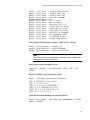
The following are the most common bnx2 driver messages:
Driver Sign on
Broadcom NetXtreme II Gigabit Ethernet Driver
bnx2 v1.6.3c (July 23, 2007)
CNIC Driver Sign on
Broadcom NetXtreme II cnic v1.1.19 (Sep 25, 2007)
NIC Detected
eth#: Broadcom NetXtreme II BCM5708 1000Base-T (B0)
PCI-X 64-bit 133MHz found at mem f6000000, IRQ 16, node
addr 0010180476ae
cnic: Added CNIC device: eth0
Link Up and Speed Indication
bnx2: eth# NIC Link is Up, 1000 Mbps full duplex
Link Down Indication
bnx2: eth# NIC Link is Down
MSI enabled successfully (bnx2 only)
bnx2: eth0: using MSI
62
AT-2872SX ExpressCard Fast Ethernet Fiber Module Installation and User’s Guide
Checking bnx2i Driver Messages
The following are the most common bnx2i driver messages:
BNX2I Driver signon
Broadcom NetXtreme II iSCSI Driver bnx2i v1.0.30 (Sep
29, 2007)
Network port to iSCSI transport name binding
bnx2i: netif=eth2, iscsi=bcm570x-050000
bnx2i: netif=eth1, iscsi=bcm570x-030c00
Driver completes handshake with iSCSI offload-enabled CNIC device
bnx2i [05:00.00]: ISCSI_INIT passed
Note
This message is displayed only when the user attempts to make an
iSCSI connection.
Driver detects iSCSI offload is not enabled on the CNIC device
bnx2i: iSCSI not supported, dev=eth3
bnx2i: bnx2i: LOM is not enabled to offload iSCSI
connections, dev=eth0
Driver unable to allocate TCP port for iSCSI connection
bnx2i: run 'bnx2id' daemon to alloc TCP ports
Exceeds maximum allowed iSCSI connection offload limit
bnx2i: unable to allocate iSCSI context resources
Network route to target node and transport name binding are two
different devices
bnx2i: conn bind, ep=0x... ($ROUTE_HBA) does not belong
to hba $USER_CHOSEN_HBA
where
ROUTE_HBA is the net device on which connection was offloaded based
on route information
USER_CHOSEN_HBA is the HBA to which target node is bound (using
iscsi transport name)
63
Chapter 4: Installing the Linux Drivers
Target cannot be reached on any of the CNIC devices
bnx2i: check route, cannot connect using cnic
Network route is assigned to network interface, which is down
bnx2i: check route, hba not found
Attempting to offload iSCSI connection onto a Jumbo Frame-enabled
device
bnx2i: eth# network i/f mtu is set to #mtu
bnx2i: iSCSI HBA can support mtu of 1500
Note
Change mtu to 1500 using ifconfig and restart the interface in order
to offload iSCSI connections.
SCSI-ML initiated host reset (session recovery)
bnx2i: attempting to reset host, #3
CNIC detects iSCSI protocol violation - Fatal errors
bnx2i:
bnx2i:
bnx2i:
bnx2i:
bnx2i:
bnx2i:
bnx2i:
bnx2i:
bnx2i:
bnx2i:
bnx2i:
bnx2i:
bnx2i:
bnx2i:
bnx2i:
bnx2i:
bnx2i:
bnx2i:
bnx2i:
bnx2i:
bnx2i:
bnx2i:
bnx2i:
bnx2i:
64
iscsi_error
iscsi_error
iscsi_error
iscsi_error
iscsi_error
iscsi_error
iscsi_error
iscsi_error
iscsi_error
iscsi_error
iscsi_error
iscsi_error
iscsi_error
iscsi_error
iscsi_error
iscsi_error
iscsi_error
iscsi_error
iscsi_error
iscsi_error
iscsi_error
iscsi_error
iscsi_error
iscsi_error
-
wrong StatSN rcvd
hdr digest err
data digest err
wrong opcode rcvd
AHS len > 0 rcvd
invalid ITT rcvd
wrong StatSN rcvd
wrong DataSN rcvd
pend R2T violation
ERL0, UO
ERL0, U1
ERL0, U2
ERL0, U3
ERL0, U4
ERL0, U5
ERL0, U
invalid resi len
MRDSL violation
F-bit not set
invalid TTT
invalid DataSN
burst len violation
buf offset violation
invalid LUN field
AT-2872SX ExpressCard Fast Ethernet Fiber Module Installation and User’s Guide
bnx2i: iscsi_error - invalid R2TSN field
bnx2i: iscsi_error - invalid cmd len1
bnx2i: iscsi_error - invalid cmd len2
bnx2i: iscsi_error - pend r2t exceeds
MaxOutstandingR2T value
bnx2i: iscsi_error - TTT is rsvd
bnx2i: iscsi_error - MBL violation
bnx2i: iscsi_error - data seg len != 0
bnx2i: iscsi_error - reject pdu len error
bnx2i: iscsi_error - async pdu len error
bnx2i: iscsi_error - nopin pdu len error
bnx2i: iscsi_error - pend r2t in cleanup
bnx2i: iscsi_error - IP fragments rcvd
bnx2i: iscsi_error - IP options error
bnx2i: iscsi_error - urgent flag error
CNIC detects iSCSI protocol violation - non-FATAL, warning
bnx2i: iscsi_warning - invalid TTT
bnx2i: iscsi_warning - invalid DataSN
bnx2i: iscsi_warning - invalid LUN field
Note
The driver needs to be configured to consider certain violations as
warning and not as a critical error.
Driver puts a session through recovery
conn_err - hostno 3 conn 03fbcd00, iscsi_cid 2 cid
a1800
Reject iSCSI PDU received from the target
bnx2i - printing rejected PDU contents
[0]: 1 ffffffa1 0 0 0 0 20 0
[8]: 0 7 0 0 0 0 0 0
[10]: 0 0 40 24 0 0 ffffff80 0
[18]: 0 0 3 ffffff88 0 0 3 4b
[20]: 2a 0 0 2 ffffffc8 14 0 0
[28]: 40 0 0 0 0 0 0 0
Open-iSCSI daemon handing over session to driver
bnx2i: conn update - MBL 0x800 FBL 0x800MRDSL_I 0x800
MRDSL_T 0x2000
65
Chapter 4: Installing the Linux Drivers
Teaming with
Channel Bonding
Statistics
Linux iSCSI
Offload
With the Linux drivers, you can team adapters together using the bonding
kernel module and a channel bonding interface. For more information, see
the Channel Bonding information in your operating system documentation.
Detailed statistics and configuration information can be viewed using the
ethtool utility. See the ethtool man page for more information.
This section describes how to install and run Linux iSCSI applications.
The following recommendations apply to offloading Linux iSCSI programs:
Not all Broadcom NetXtreme II adapters support iSCSI offload.
The iSCSI session will not recover after a hot remove and hot plug.
The iSCSI driver/firmware will not offload iSCSI connections onto a
jumbo frame-enabled CNIC device.
For MPIO to work properly, iSCSI nopout should be enabled on each
iSCSI session. Refer to open-iscsi documentation for procedures on
setting up noop_out_interval and noop_out_timeout values.
In the scenario where multiple CNIC devices are in the system and the
system is booted via Broadcom's iSCSI boot solution, ensure that the
iscsi node under /etc/iscsi/nodes for the boot target is bound to the NIC
that is used for booting.
See the following sections:
“Installing User Application - bnx2id” on page 66
“Installing Open iSCSI User Applications” on page 67
“Binding iSCSI Target to Broadcom NX2 iSCSI Transport Name” on
page 68
“Making Connections to iSCSI Targets” on page 68
“Maximizing Offload iSCSI Connections” on page 69
Installing User Application - bnx2id
The bnx2id application should be installed under /sbin when bnx2i RPM
package is installed. See “Installing the Source RPM Package” on
page 52 for information. Run the bnx2id daemon before attempting to
create iSCSI connections. The driver does not establish connections to
the iSCSI target without the daemon's assistance.
bnx2id
The bnx2id daemon requires mknod and sh shell, which are standard on
any regular server. For iSCSI boot using NetXtreme II offload support,
binaries for mknod and sh need to be bundled into initrd image.
66
AT-2872SX ExpressCard Fast Ethernet Fiber Module Installation and User’s Guide
Installing Open iSCSI User Applications
Install and run the open-iscsi programs, iscsid and iscsiadm, from the
Broadcom distributed open-iscsi packages. See “Packaging” on page 51
for details. All pre-installed open-iscsi packages need to be removed
before the Broadcom iSCSI-supported packages can be installed.
To install and run the iscsid and iscsiadm programs, do the following:
1. Remove all existing open-iscsi packages.
RHEL5
rpm -e iscsi-initiator-utils
SLES10 SP1
rpm -e open-iscsi
2. Install the source RPM package. Type the following:
rpm -ivh <open-iscsi-package-name>.src.rpm
3. CD to the RPM path and build the binary driver for your kernel. Enter:
cd /usr/src/{redhat,OpenLinux,turbo,packages,rpm
..}
rpm -bb SPECS/<open-iscsi-package-name>.spec
or
rpmbuild -bb SPECS/<open-iscsi-package-name>.spec
(for RPM version 4.x.x)
Note
The RPM path is different for each Linux distribution.
4. Install the newly built package. Type:
rpm -ivh RPMS/<arch>/<open-iscsi-packagename>.<arch>.rpm
where <arch> is the machine architecture such as i386.
rpm -ivh RPMS/i386/<open-iscsi-packagename>.i386.rpm
5. Start the daemon. Type:
iscsid
67
Chapter 4: Installing the Linux Drivers
Binding iSCSI Target to Broadcom NX2 iSCSI Transport Name
By default, the open-iscsi daemon connects to discovered targets using
software initiator (transport name = 'tcp'). Users who wish to offload an
iSCSI connection onto CNIC device should explicitly change the transport
binding of the iSCSI node. This can be done using iscsiadm cli utility as
follows:
iscsiadm --mode node --targetname iqn.200406.com.broadcom:tg1 \
--portal 192.168.1.100 --op=update \
--name=node.transport_name -value=${XPORT_NAME}
where XPORT_NAME=bcm570x-xxyyzz
xx - pci bus number of the NX2 device
yy - pci device number of the NX2 device
zz - pci function number of the NX2 device
Network interface to iscsi transport name binding can be obtained by
executing the following.
dmesg | grep “bnx2i: netif”
Sample output in a system with two NetXtreme II devices:
bnx2i: netif=eth1, iscsi=bcm570x-050000
bnx2i: netif=eth0, iscsi=bcm570x-030000
If you wish to switch back to use the software initiator, enter the following:
iscsiadm --mode node --targetname iqn.200406.com.broadcom:tg1 \
--portal 192.168.1.100 --op=update \
--name=node.transport_name --value=tcp
Making Connections to iSCSI Targets
Refer to open-iscsi documentation for a comprehensive list of iscsiadm
commands. This is a sample list of commands to discovery targets and to
create iscsi connections to a target.
Adding static entry
iscsiadm -m node -p <ipaddr[:port]> -T iqn.200705.com.broadcom:target1 -o new
68
AT-2872SX ExpressCard Fast Ethernet Fiber Module Installation and User’s Guide
iSCSI target discovery using 'SendTargets'
iscsiadm -m discovery --type sendtargets -p
<ipaddr[:port]>
Login to target using 'iscsiadm' command
iscsiadm --mode node --targetname <iqn.targetname> -portal <ipaddr[:port]> --login
List all drives active in the system
'fdisk -l'
Maximizing Offload iSCSI Connections
With default driver parameters set, which includes 128 outstanding
commands, bnx2i can offload a maximum of 28 iSCSI connections. This is
not a hard limit, but simple on-chip resource allocation math. The bnx2i
driver can offload > 28 connections by reducing the shared queue size
which, in turn, limits the maximum outstanding tasks on a connection. See
“Setting Values for Optional Properties” on page 58 for information on
sq_size and rq_size. Driver logs the following message to syslog when the
maximum allowed connection offload limit is reached - “bnx2i: unable to
allocate iSCSI context resources.”
69
Chapter 4: Installing the Linux Drivers
70
Appendix A
Specifications
Physical Specifications
This section provides the dimensions and weight of the module.
Dimensions:
13.7 cm x 3.4 cm (5.4 in. x 1.3 in.)
Weight:
45.36 g (.10 lbs.)
Environmental Specifications
The following environmental specifications apply to the AT-2872SX
ExpressCard module:
Operating Temperature:
0°C to 40°C (+32°F to +104°F)
Storage Temperature:
-20°C to +70°C (-4°F to +158°F)
Operating Humidity:
30% to 90% (noncondensing)
Storage Humidity:
10% to 95% (noncondensing)
Maximum Operating Altitude: 3,048 m (10,000 ft.)
Power Specifications
The following power specifications apply to the AT-2872SX ExpressCard
module:
Operating Voltage:
3.3V
Power Consumption: 3.4 Watts, @ +3.3V
71
Appendix A: Specifications
Performance Specification
The following performance specification apply to the AT-2872SX
ExpressCard module:
MTBF
1,650,000 hours
Operating Specifications
The following operating specifications apply to the AT-2872SX
ExpressCard module:
72
Output Optical Power (min/max):
-9.5/-1.5 dBm
Input Optical Power (min):
-17 dBm
Wavelength:
850 nm
Appendix B
Cleaning Fiber Optic Connectors
The fiber optic connector consists of a fiber optic plug and its adapter. The
end of the fiber optic cable is held in the core of the ferrule in the plug.
Light signals are transmitted through the core of the fiber. Even minor
smudges or dirt on the end face of the fiber, completely invisible to the
naked eye, can disrupt light transmission and lead to failure of the
component or of the entire system. Therefore, it is of utmost importance to
clean all fiber optic connectors before use.
Figure 13 shows the ferrule in an SC connector.
177
Ferrule
Figure 13. Ferrule in an SC Connector Plug
Figure 14 shows part of the end face of an unclean and clean ferrule.
156
Unclean
Clean
Figure 14. Unclean and Clean Ferrule
This appendix provides the following procedures:
“Using a Cartridge-Type Cleaner” on page 74
“Using a Swab” on page 76
73
Appendix B: Cleaning Fiber Optic Connectors
Using a Cartridge-Type Cleaner
PUSH OPEN
Di
re
c
A
PEng
TAWipi tion
Fiber optic cartridge cleaners are available from many vendors and are
typically called “cartridge cleaners,” as shown in Figure 15.
Figure 15. Cartridge Cleaner
Note
Do not use compressed air or aerosol air to clean a fiber optic
connector.
To clean a fiber optic connector using a cartridge cleaner, do the following.
1. With one hand, hold the cartridge cleaner and push the lever on the
cleaning cartridge in the direction of the arrow to expose the cleaning
surface, as shown in Figure 16.
2. Place the ferrule tip on the exposed cleaning surface and rub the
ferrule in a downward direction, as shown in Figure 16.
Figure 16. Rubbing the Ferrule Tip on the Cleaning Surface
74
AT-2872 SX Gigabit Ethernet Fiber ExpressCard Interface User’s Guide
Note
Rub the ferrule tip on the cleaning surface in one direction only.
3. When you reach the end of the cleaning surface, pick up the ferrule tip,
rotate and place it at the top and rub downwards at least 2 times.
Caution
Failing to pick up the ferrule tip when you reach the bottom of the
cleaning surface can result in static electricity that can damage the
fiber optic cable.
4. If desired, repeat steps 3 and 4.
5. If a fiber inspection scope is available, use the scope to inspect the
ferrule end face to make sure that it is clean.
6. Reconnect the cable to the port or protect the ferrule tip with a dust
cap.
Note
Always keep a dust cap on a fiber optic cable when it is not in use.
Note
Do not touch the end face of the ferrule in the connector.
75
Appendix B: Cleaning Fiber Optic Connectors
Using a Swab
Specially treated swabs (stick cleaners) are available for cleaning inside
connector adapters or hard-to-reach ferrule tips. These swabs, often
referred to as “lint free” or “alcohol free” swabs, are available from many
vendors, as shown in Figure 17. Stick cleaners are available in both 2.5
mm and 1.25 mm sizes for use on SC and MU connectors respectively.
Note
NEVER use a household cotton swab and/or alcohol to clean a fiber
optic connector. This may leave a residue on the ferrule tip.
Figure 17. Lint-Free and Alcohol-Free Swabs
Note
Do not use compressed air or aerosol air to clean a fiber optic
connector.
To clean a recessed ferrule using a swab, do the following.
1. Insert the swab into the adapter as shown in Figure 16 and rub the
ferrule tip with the swab.
157
Figure 18. Cleaning a Recessed Ferrule
2. If desired, repeat step 1.
76
AT-2872 SX Gigabit Ethernet Fiber ExpressCard Interface User’s Guide
3. If a fiber inspection scope is available, use the scope to inspect the
connector to make sure that it is clean and to check for scratches, pits,
or other problems that may affect performance.
Note
Always keep a dust cap on a fiber optic cable when it is not in use.
77
Appendix B: Cleaning Fiber Optic Connectors
78