1
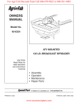
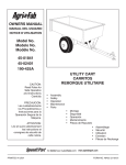
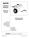
™
owners manual
Model No.
45-0414
45-0415
125 LB. TOW
BROADCAST SPREADER
CAUTION:
Read Rules for
Safe Operation
and Instructions
Carefully
•
•
•
•
•
Safety
Assembly
Operation
Maintenance
Parts
the fastest way to purchase parts www.speedepart.com
PRINTED IN USA
FORM NO. 40454 (11/06)
RULES FOR SAFE OPERATION
Any power equipment can cause injury if operated improperly or if the user does not understand how to operate the equipment.
Exercise caution at all times when operating equipment.
•
Read the towing vehicle owners manual and towing
vehicle safety rules. Know how to operate your tractor
before using the broadcast spreader attachment.
Read the chemical label instructions and cautions for
handling and applying the chemicals purchased for
spreading.
Wear eye and hand protection when handling and when
applying lawn or garden chemicals.
Never operate tractor and spreader attachment without
wearing substantial footwear, and do not allow anyone
to ride or sit on spreader attachment frame.
Follow maintenance and lubrication instructions as
outlined in this manual.
•
•
•
•
•
•
•
•
Always begin with the transmission in first (low) gear and
with the engine at low speed, and gradually increase
speed as conditions permit.
When towing broadcast spreader do not drive too close
to a creek or ditch and be alert for holes and other
hazards which could cause you to loose control of the
broadcast spreader and tractor.
Before operating vehicle on any grade (hill) refer to the
safety rules in the vehicle owner's manual concerning
safe operation on slopes. Stay off steep slopes!
Never allow children to operate the tractor or spreader
attachment, and do not allow adults to operate without
proper instructions.
LOOK FOR THIS SYMBOL TO POINT OUT IMPORTANT SAFETY PRECAUTIONS.
IT MEANS — ATTENTION! BECOME ALERT! YOUR SAFETY IS INVOLVED.
CARTON CONTENTS
1
2
4
6
3
5
8
7
12
11
14
10
9
1
2
3
4
5
6
7
13
8
9
10
11
12
13
14
Drawbar Tube
Flow Control Rod
Bent Hitch Brace
Flow Control Bracket
Hopper Assembly
Hopper Screen
Straight Hitch Brace
Control Tube
RH Wheel
LH Wheel
Flow Control Arm
Top Hitch (tall)
Bottom Hitch (short)
Reinforcement Strap
HARDWARE PACKAGE
G
K
E
B
A
C
D
H
L
I
M
P
J
S
T
Q
N
U
O
R
V
W
X
REF QTY DESCRIPTION
A
2 Hex Bolt, 3/8" x 2-1/4"
B
3 Hex Bolt, 1/4" x 2-1/2"
C
5 Hex Bolt, 1/4" x 1-3/4"
D
8 Hex Bolt, 1/4" x 1-1/2"
E
1 Hex Bolt, 1/4" x 1"
G
2 Nylock Nut, 3/8"
H
18 Nylock Nut, 1/4"
I
2 Nylon Washer
J
4 Washer, Small
K
1 Hair Cotter Pin
L
1 Carriage Bolt, 1/4-20 x 3/4"
M
1 Cotter Pin, 9/64 x 1-1/2"
REF QTY DESCRIPTION
N
1 Spacer, .64 x .84 x 1
O
1 Spacer, .64 x 1 x 2.94
P
6 Washer, Large
Q
1 Wing Nut, 1/4"
R
1 Spacer, .39 x .56 x .62
S
1 Spring
T
1 Adjustable Stop
U
1 Grip
V
1 Hitch Pin
W
1 Engagement Bracket
X
1 Spring
ASSEMBLY INSTRUCTIONS
After assembling bracket (W) to axle, tighten both bolts.
Loosen bolt through axle just enough that bracket (W) can
pivot but will stay in place. See figure 4.
TOOLS REQUIRED FOR ASSEMBLY
(1)
(2)
(2)
(2)
Pliers
7/16" Wrenches
1/2" Wrenches
9/16" Wrenches
LARGE HOLE
LONG END
TO OUTSIDE
TIGHTEN WITH WRENCHES
REINFORCEMENT STRAP
H
W
H
H
D
P
H
D
D
R
WHEEL
WITH BOLT
FIGURE 4
FIGURE 1
N
SMALL HOLE
Assemble bent hitch braces and then straight hitch braces
to inside of spreader frame. Straight hitch braces must be
to inside of bent hitch braces. See figure 5.
P
LARGE HOLE
TIGHTEN WITH FINGERS
O
P
D
FIGURE 2
LONG END
TO INSIDE
P
H
M
BENT
HITCH
BRACE
SMALL HOLE
FIGURE 5
WHEEL
WITHOUT BOLT
FIGURE 3
STRAIGHT
HITCH
BRACE
Assemble drawbar tubes to inside of lower handle tubes.
Assemble straight hitch braces to outside of lower handle
tubes. See figure 6.
LOWER HANDLE TUBE
TOP HITCH (TALL)
C
V
A
DRAWBAR TUBE
H
BOTTOM HITCH (SHORT)
G
H
K
STRAGHT
HITCH
BRACE
FIGURE 8
B
FIGURE 6
SCREEN
CLIP
C
CONTROL TUBE
H
B
H
FIGURE 9
TIGHTEN FASTENERS
Tighten fasteners in the order below.
FIGURE 6
FIGURE 7
FIGURE 8
FIGURE 9
H
J
D
FLOW CONTROL
BRACKET
J
FLOW
CONTROL
ROD
FIGURE 13
FIGURE 10
S
FLOW CONTROL ARM
U
H
E
FIGURE 14
J
I
Slip the small spring (X) onto the end flow control rod and
then attach it to the pattern plate. See figure 15.
FIGURE 11
Q
X
J
T
FIGURE 15
L
CONTINUE TO NEXT PAGE
FIGURE 12
OPERATION
TIGHTEN FASTENERS
FIGURE 11
Tighten the nut (H) and then loosen
just enough that the flow control arm
moves freely.
HOW TO USE YOUR SPREADER
SETTING THE FLOW CONTROL
(Refer to figure 16 and 17)
1. Loosen the nylon wing nut, set the adjustable stop to
the desired flow rate setting and retighten the wing nut.
The higher the setting number, the wider the opening
in the bottom of the hopper.
2. Refer to the Application Chart on page 8 and to the
instructions on the fertilizer bag to select the proper
flow rate setting.
3. Pull the flow control arm from the "OFF" position and
rest it against the adjustable stop for the “ON” position.
Push the flow control arm past the stop, toward the
hopper for the “OFF” position.
CALIBRATING FLOW CONTROL ARM
Flow control mounting bracket (figure 16 and 17)
a. Set adjustable stop at "OFF" position. Move flow control
arm against adjustable stop.
b. Slide flow control mounting bracket along control tube
until closure plate in bottom of hopper just closes.
c. Snug the nuts just enough to hold flow control mounting
bracket in place.
d. Set adjustable stop at "5". With flow control arm resting
against stop, verify that closure plate is open about half
way.
e. If closure plate is not open about half way, slide flow
control mounting bracket up or down control tube until
closure plate will open about half way at "5" and will
close completely when arm is pushed past adjustable
stop to "OFF" position. Tighten the 5/16" nylock hex
nuts.
USING THE PATTERN ADJUSTMENT PLATE
The pattern adjustment plate is used to adjust the flow
of material being spread to the left or right side. The
pattern adjustment plate is the bottom stainless steel plate
underneath the hopper.
The adjustment of the pattern plate is sensitive. It is
recommended that you test your spread pattern in a small
area first.
"OFF"
1. To adjust the flow to be heavier to the left side, tighten
the thumbscrew so the plate will not pull out as far.
See figure 18.
2. To adjust the flow to be heavier to the right side,
loosen the thumbscrew so the plate will pull out farther.
See figure 18.
FIGURE 16
"5"
THUMB SCREW
FIGURE 18
FIGURE 17
USING YOUR SPREADER
IMPORTANT: Application rates shown in the chart are
affected by humidity and by the moisture content of
the material (granular and pellet). Some minor setting
adjustments may be necessary to compensate for this
condition.
The use of powdered lawn chemicals is not recommended,
due to difficulty in obtaining a satisfactory or consistent
broadcast pattern.
1. Determine approximate square footage of area to be
covered and estimate amount of material required.
2. Before filling the hopper, set the adjustable stop to the
proper setting. Refer to the Application Chart on this page
and to the instructions on the fertilizer bag to select the
proper flow rate setting.
3. Move the flow control arm past the adjustable stop to the
“OFF” position so that the closure plate is shut.
4. Fill the hopper, breaking up any lumpy fertilizer.
5. The Application Chart is calculated for light-to-heavy
application at a walking speed of 3 mph, or 100 ft. in 23
seconds. A variation in speed will require an adjustment
of the flow rate to maintain the same coverage. The faster
you travel, the wider the broadcast width.
6. Always start the spreader in motion before opening the
closure plate.
7. Always shut the closure plate before turning or stopping
the spreader.
8. If fertilizer is accidentally deposited too heavily in a small
area, soak the area thoroughly with a garden hose or
sprinkler to prevent burning of the lawn.
9. To insure uniform coverage, make each pass so that the
broadcast pattern slightly overlaps the pattern from the
previous pass as shown in figure 19. The approximate
broadcast widths for different materials are shown in the
Application Diagram figure 19.
10. When broadcasting weed control fertilizers, make sure the
broadcast pattern does not hit evergreen trees, flowers
or shrubs.
APPLICATION CHART
MATERIAL
TYPE
FERTILIZER
Powder
Granular
Pelleted
Organic
GRASS SEED
Fine
Coarse
ICE MELTER
FLOW SETTING
3 MPH
(100 FT. IN 23 SEC.)
SPREAD
WIDTH IN
FEET
3-5
3-5
3-5
6-8
3-4
8-10
10-12
6-8
3-4
4-5
6-8
6-7
8-9
10-12
OPERATING SPEED - 3 MPH. (100 ft. in 23 seconds)
REFER
TO
CHARTS
OVERLAP
FIGURE 19
MAINTENANCE
CHECK FOR LOOSE FASTENERS
GREASE
1. Before each use, make a thorough visual check of
the spreader for any bolts and nuts which may have
loosened. Retighten any loose bolts and nuts.
OIL
CHECK FOR WORN OR DAMAGED PARTS
2. Check for worn or damaged parts before each use.
Repair or replace parts if necessary.
CHECK TIRE INFLATION
3. Check if tires are adequately inflated before each use.
Do not inflate tires beyond maximum recommended
pressure.
HAIRPIN
HAIRPIN
FIGURE 20
CAUTION: DO NOT inflate tires beyond the
maximum recommended pressure printed
on side of tire.
STORAGE
CLEANING
1. Rinse inside of hopper and exterior of spreader and
allow to dry before storing.
4. Rinse inside of hopper and exterior of spreader and
allow to dry before storing.
2. Store in a clean, dry area.
LUBRICATE (See figure 20)
5. Remove one small and two large hairpins and separate
the gearbox housings.
SERVICE AND ADJUSTMENTS
6. Lightly apply automotive grease as needed to the
gears.
1. If the axle and gear assembly is disassembled, mark
down the positions of the parts as they are removed.
The large gear position in relation to the small gear
determines which direction the spreader plate will
spin. Be sure to reassemble them in their original
positions. (Refer to parts exploded view on page 10).
Ensure washer (Refer to item 33 on page 10 and 11)
is in place when assembling the axle components.
Add grease to gears.
7. Oil the nylon bushings on the vertical sprocket shaft.
Apply grease to the axle at least once a year, or more
often as needed.
8. Oil (idler) wheel at least once a year or more often as
needed.
9. Install gearbox housings and secure with hairpins.
2. If the agitator hairpin becomes damaged or worn, it
can be replaced. Remove old agitator hairpin from
hole in impeller shaft and replace with new agitator
hairpin. See figure 21.
SPROCKET
SHAFT
AGITATOR
HAIRPIN
FIGURE 21
REPAIR PARTS FOR BROADCAST SPREADER
MODELS 45-0414, 45-0415
64
9
6
5
9
1
34
6
5
37
43
9
7
5
20
68
45
62
21
33
31
8
31
25
55
54
41
52
26
28
33 31 30
2
29
17
8 13
14
10
40
8
22
25
38
15 8
18
19
29
63 8
19
16 46
66
33
8
42
8
45
3
8
32
33
35
52
9
12
52
5
53
65
39
61
45
27
23 24
62
8
11
67
45
4
60
8
33
33 36
44
44
8
4
58
3
57
60
9
9
33
50
48
8
47
49
8
47
8
51
8
56
45
56
10
59
REPAIR PARTS FOR BROADCAST SPREADER
MODELS 45-0414, 45-0415
REF. PART NO. QTY DESCRIPTION
REF. PART NO. QTY DESCRIPTION
1
44466
1
Hopper, Spreader (125 lb.)
35
23668
1
Spacer, .64 x 1 x 2.94
2
48842
1
Tube, Frame (45-0414)
36
48857
1
Spacer, .64 x .84 x 1
48842SS
1
Tube, Frame (45-0415)
37
48934
1
Hairpin, Agitator
3
25755
2
Handle, Lower (45-0414)
38
25763
1
Adjustable Stop
25755SS
2
Handle Lower (45-0415)
39
49903
1
Carriage Bolt, 1/4-20 x 3/4" *
4
741-0249
4
Bearing, Flanged
40
49931
1
Thumb Screw, 1/4-20 x 1-1/4" *
5
1543-69
8
Washer, Nylon
41
47141
1
Wing Nut, 1/4-20
6
49890
4
Washer, 1/4" *
42
43848
1
Control Arm Grip
7
25672
2
Clip
43
49901
1
Spring
8
49891
27
Nylock Nut, 1/4-20 *
44
49908
3
Hex Bolt, 1/4-20 x 2-1/2" *
9
49892
11
Hex Bolt, 1/4-20 x 1-3/4" *
45
49909
8
Hex Bolt, 1/4-20 x 1-1/2" *
10
65457
1
Closure Guide
46
40520
1
Nylon Nut
11
25757
1
Plate, Pattern
47
23525
2
Hitch Brace (bent)
12
23533
1
Plate, Closure
48
23014
1
Hitch Bracket
13
44285
1
Bushing, Hopper Bottom
49
23687
1
Hitch Bracket
14
49894
4
Slot Truss Bolt, 10-32 x 1/2" *
50
40305
2
Hex Bolt, 3/8-16 x 2-1/4" *
15
43882
2
Pop Rivet, 3/16 *
51
40306
2
Nylock Nut, 3/8-16 *
16
49895
4
Nylock Nut, 10-32 *
52
40308
4
Washer, .3437 x .6875 *
17
25758
1
Link, Flow Control
53
40310
1
Hex Bolt, 1/4-20 x 1" *
18
25917
1
Slide Gate Angle Bracket
54
26026
1
Engagement Bracket
19
40199
2
Hex Bolt, 1/4-20 x 3/4" *
55
23658
1
Spacer, .39 x .56 x .62
20
04367
1
Spreader Impeller
56
26023
2
Hitch Brace (straight)
21
49896
1
Shaft, Impeller
57
49911
1
Cotter Pin, 9/64 x 1-1/2" *
22
26027
1
Axle
58
23353
1
Hitch Pin, 3/8 x 3"
23
49910
2
Spacer, Axle Tube
59
43343
1
Hair Cotter Pin, 3/32 x 2-5/16"
24
49798
2
Fitting, Grease 1/4"
60
40291
2
Drawbar Tube (45-0414)
25
47212
2
Housing, Large Gear
40291SS
2
Drawbar Tube (45-0415)
26
47204
1
Yoke, Large
40292
1
Control Tube (45-0414)
27
47209
1
Gear, Large
40292SS
1
Control Tube (45-0415)
28
47205
1
Gear, Small
62
40355
2
Wheel
29
49897
2
Clip, Hairpin 7/8
63
44695
1
Bowed Washer
30
49898
1
Clip, Hairpin 5/8
64
47441
1
Spreader Screen
31
46055
3
Pin, Spring 1/8 x 1"
65
24915
1
Flow Control Bracket
32
43659
1
Pin, Spring 3/16 x 1"
66
26004
1
Control Arm
33
49899
7
Washer
67
26142
1
Cross Frame Strap
34
40304
1
Rod, Flow Control
68
40526
1
Spring
40454
1
Owners Manual
61
* Stainless Steel Fastener
the fastest way to purchase parts www.speedepart.com
11
the fastest way to purchase parts www.speedepart.com
© 2006 Agri-Fab Inc.
REPAIR PARTS
Agri-Fab, Inc.
809 South Hamilton
Sullivan, IL. 61951
217-728-8388
www.agri-fab.com