1
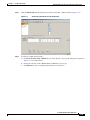
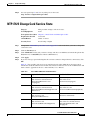
C H A P T E R
11
Change Card Settings
This chapter explains how to change transmission settings on cards in a Cisco ONS 15600.
Before You Begin
As necessary, complete the “NTP-E57 Document Existing Provisioning” procedure on page 7-2.
Before performing the following procedures, investigate all alarms and clear any trouble conditions.
Refer to the Cisco ONS 15600 Troubleshooting Guide as necessary.
This section lists the chapter procedures (NTPs). Turn to a procedure for applicable tasks (DLPs).
1.
NTP-E157 Provision a Multirate PPM, page 11-2—Complete this procedure to provision a multirate
pluggable port module (PPM), for the ASAP card. If a multirate PPM was preprovisioned, this
procedure is unnecessary.
2.
NTP-E151 Provision an Optical Line Rate, page 11-3—Complete this procedure to provision the
optical line rate on a multirate PPM for the ASAP card. Single-rate PPMs do not need to be
provisioned.
3.
NTP-E150 Change the Optical Line Rate, page 11-4—As needed, complete this procedure to edit
optical line rates for multirate PPMs on the ASAP card.
4.
NTP-E149 Delete Pluggable Port Modules, page 11-5—As needed, complete this procedure to
delete PPMs for the ASAP card.
5.
NTP-E66 Modify Line and Status Thresholds for Optical Ports, page 11-6—As needed, complete
this procedure to change line (drop) and threshold settings for all OC-N cards.
6.
NTP-E105 Change an Optical Port to SDH, page 11-12—As needed, complete this procedure to
change an optical port from SONET to SDH.
7.
NTP-E125 Change Card Service State, page 11-13—As needed, complete this procedure to change
card service state.
Cisco ONS 15600 Procedure Guide, R5.0
February 2008
11-1
Chapter 11
Change Card Settings
NTP-E157 Provision a Multirate PPM
NTP-E157 Provision a Multirate PPM
Purpose
This procedure provisions a multirate pluggable port modules (PPMs) in
CTC.
Tools/Equipment
None
Prerequisite Procedures NTP-E147 Install the ASAP Card, page 2-5
DLP-E211 Install the ASAP 4PIO Modules, page 18-12, as needed
DLP-E215 Install an SFP, page 18-14, as needed
Required/As Needed
Required
Onsite/Remote
Onsite or remote
Security Level
Provisioning or higher
Step 1
Complete the “DLP-E26 Log into CTC” task on page 16-39 to log into an ONS 15600 on the network.
Step 2
Click the Alarms tab:
a.
Verify that the alarm filter is not turned on. See the “DLP-E157 Disable Alarm Filtering” task on
page 17-50 as necessary.
b.
Verify that no unexplained conditions appear on the network. If unexplained conditions appear,
resolve them before continuing. Refer to the Cisco ONS 15600 SONET Troubleshooting Guide.
c.
Complete the “DLP-E76 Export CTC Data” task on page 16-98 to export alarm and condition
information.
Step 3
In node view, double-click the ASAP card where you want to provision PPM settings.
Step 4
Click the Provisioning > Pluggable Port Modules tabs.
Step 5
In the Pluggable Port Modules pane, click Create. The Create PPM dialog box appears.
Step 6
In the Create PPM dialog box, complete the following:
•
PPM—Click the slot number where the SFP is installed from the drop-down list.
•
PPM Type—Click the number of ports supported by your SFP from the drop-down list. If only one
port is supported, PPM (1 port) is the only menu option.
Step 7
Click OK. The newly created port appears on the Pluggable Port Modules pane. The row on the
Pluggable Port Modules pane turns light blue and the Actual Equipment Type column lists the equipment
name.
Step 8
Verify that the PPM appears in the list on the Pluggable Port Modules pane. If it does not, repeat Steps
5 through 8.
Step 9
Repeat the task to provision a second PPM.
Step 10
Click OK.
Step 11
Continue with the “NTP-E151 Provision an Optical Line Rate” procedure on page 11-3 to provision the
line rate.
Stop. You have completed this procedure.
Cisco ONS 15600 Procedure Guide, R5.0
11-2
February 2008
Chapter 11
Change Card Settings
NTP-E151 Provision an Optical Line Rate
NTP-E151 Provision an Optical Line Rate
Purpose
This procedure provisions the line rate on a multirate pluggable port
module (PPM). Single-rate small-form factor pluggables (SFPs) or 4-port
I/O modules (4PIOs) do not need line rate provisioning.
Tools/Equipment
None
Prerequisite Procedures NTP-E148 Preprovision an SFP Slot, page 2-8 or
NTP-E157 Provision a Multirate PPM, page 11-2
Required/As Needed
Required
Onsite/Remote
Onsite or remote
Security Level
Provisioning or higher
Step 1
Complete the “DLP-E26 Log into CTC” task on page 16-39 to log into an ONS 15600 on the network.
Step 2
Click the Alarms tab:
a.
Verify that the alarm filter is not turned on. See the “DLP-E157 Disable Alarm Filtering” task on
page 17-50 as necessary.
b.
Verify that no unexplained conditions appear on the network. If unexplained conditions appear,
resolve them before continuing. Refer to the Cisco ONS 15600 SONET Troubleshooting Guide.
c.
Complete the “DLP-E76 Export CTC Data” task on page 16-98 to export alarm and condition
information.
Step 3
In node view, double-click the ASAP card where you want to provision the line rate.
Step 4
Click the Provisioning > Pluggable Port Modules tabs.
Step 5
In the Pluggable Ports pane, click Create. The Create Port dialog box appears.
Step 6
In the Create Port dialog box, complete the following:
•
Port—Click the PPM number and port number from the drop-down list. The first number indicates
the PPM and the second number indicates the port number on the PPM. For example, the first PPM
with one port displays as 1-1 and the second PPM with one port displays as 2-1. When a 4PIO is
present on an ASAP card, the port is identified as 4PIO#-PPM#-Port# (for example 4-4-1). The 4PIO
number can be 1 to 4, the PPM number can be 1 to 4, but the port number is always 1.
•
Port Type—Click the type of port from the drop-down list. The port type menu displays the
supported port rates on your PPM. See Table 11-1 for definitions of the supported rates on the ASAP
card.
Step 7
Click OK.
Step 8
Repeat Steps 5 through 7 to configure the port rates as needed.
Table 11-1
Card
ASAP
PPM Port Types
Port Type
•
OC-3—155 Mbps
•
OC-12—622 Mbps
•
OC-48—2.48 Gbps
•
ETHER—10 Gbps Ethernet
Cisco ONS 15600 Procedure Guide, R5.0
February 2008
11-3
Chapter 11
Change Card Settings
NTP-E150 Change the Optical Line Rate
Step 9
Click OK. The row on the Pluggable Ports pane turns light blue until the actual SFP is installed and then
the row turns white.
Stop. You have completed this procedure.
NTP-E150 Change the Optical Line Rate
Purpose
This procedure changes PPM port rates for the ASAP card. Perform this
procedure if you want to change the port rate on a multi-rate SFP that is
already provisioned.
Tools/Equipment
None
Prerequisite Procedures NTP-E157 Provision a Multirate PPM, page 11-2
Required/As Needed
As needed
Onsite/Remote
Onsite or remote
Security Level
Provisioning or higher
Step 1
Complete the “DLP-E26 Log into CTC” task on page 16-39 to log into an ONS 15600 on the network.
Step 2
Click the Alarms tab:
a.
Verify that the alarm filter is not turned on. See the “DLP-E157 Disable Alarm Filtering” task on
page 17-50 as necessary.
b.
Verify that no unexplained conditions appear on the network. If unexplained conditions appear,
resolve them before continuing. Refer to the Cisco ONS 15600 SONET Troubleshooting Guide.
c.
Complete the “DLP-E76 Export CTC Data” task on page 16-98 to export alarm and condition
information.
Step 3
In node view, double-click the ASAP card where you want to edit the PPM port rate.
Step 4
Click the Provisioning > Pluggable Port Modules tabs.
Step 5
Click the port with the port rate you want to change in the Pluggable Ports pane. The highlight changes
to dark blue.
Step 6
Click Edit. The Edit Port Rate dialog box appears.
Step 7
In the Change To field, use the drop-down menu to select the new port rate and click OK.
Step 8
Click Yes on the Confirm Port Rate Change dialog box.
Stop. You have completed this procedure.
Cisco ONS 15600 Procedure Guide, R5.0
11-4
February 2008
Chapter 11
Change Card Settings
NTP-E149 Delete Pluggable Port Modules
NTP-E149 Delete Pluggable Port Modules
Purpose
This procedure deletes PPM provisioning for SFPs on the ASAP card.
Tools/Equipment
None
Prerequisite Procedures NTP-E157 Provision a Multirate PPM, page 11-2
Required/As Needed
As needed
Onsite/Remote
Onsite or remote
Security Level
Provisioning or higher
Step 1
Complete the “DLP-E26 Log into CTC” task on page 16-39 to log into an ONS 15600 on the network.
Step 2
Click the Alarms tab:
Step 3
a.
Verify that the alarm filter is not turned on. See the “DLP-E157 Disable Alarm Filtering” task on
page 17-50 as necessary.
b.
Verify that no unexplained conditions appear on the network. If unexplained conditions appear,
resolve them before continuing. Refer to the Cisco ONS 15600 SONET Troubleshooting Guide.
c.
Complete the “DLP-E76 Export CTC Data” task on page 16-98 to export alarm and condition
information.
You cannot delete a port on a PPM: if it is in service, part of a protection group, has a communications
channel termination in use, is used as a timing source, has circuits, or has overhead circuits. As needed,
complete the following procedures and task:
•
NTP-E61 Modify or Delete Optical 1+1 Port Protection Settings, page 10-4
•
NTP-E62 Change Node Timing, page 10-4
•
NTP-E128 Modify or Delete Communications Channel Terminations and Provisionable Patchcords,
page 10-7
•
NTP-E52 Modify and Delete Circuits, page 9-2
•
NTP-E134 Modify and Delete Overhead Circuits, page 9-3
•
DLP-E115 Change the Service State for a Port, page 17-14
Step 4
In node view, double-click the ASAP card where you want to delete PPM settings.
Step 5
Click the Provisioning > Pluggable Port Modules tabs.
Step 6
To delete a PPM and the associated ports:
Step 7
a.
Click the PPM line that appears in the Pluggable Port Modules pane. The highlight changes to dark
blue.
b.
Click Delete. The Delete PPM dialog box appears.
c.
Click Yes. The PPM provisioning is removed from the Pluggable Port Modules pane and the
Pluggable Ports pane.
Verify that the PPM provisioning is deleted:
•
If the PPM was pre-provisioned, CTC shows an empty slot in CTC after it is deleted.
•
If the SFP or 4PIO is physically present when you delete the PPM provisioning, CTC transitions to
the deleted state, the ports (if any) are deleted, and the PPM is represented as a gray graphic in CTC.
The SFP or 4PIO can be provisioned again in CTC, or the equipment can be removed, in which case
the removal causes the graphic to disappear.
Cisco ONS 15600 Procedure Guide, R5.0
February 2008
11-5
Chapter 11
Change Card Settings
NTP-E66 Modify Line and Status Thresholds for Optical Ports
Note
If you need to remove the SFP, see the “DLP-E216 Remove an SFP” procedure on page 18-15.
If you need to remove the 4PIO, see the “DLP-E217 Remove a 4PIO Module” procedure on
page 18-16.”
Stop. You have completed this procedure.
NTP-E66 Modify Line and Status Thresholds for Optical Ports
Purpose
This procedure changes line settings (line type, coding, and length), line
status (in service or out of service), and performance monitoring thresholds
for OC-48, OC-192 cards, and OC-N ports on ASAP cards.
Tools/Equipment
None
Prerequisite Procedures NTP-E157 Provision a Multirate PPM, page 11-2
Required/As Needed
As needed
Onsite/Remote
Onsite or remote
Security
Provisioning or higher
Step 1
Complete the “DLP-E26 Log into CTC” task on page 16-39 at the node where you want to change the
settings. If you are already logged in, continue with Step 2.
Step 2
Complete the “NTP-E69 Back Up the Database” procedure on page 14-4.
Step 3
On the shelf graphic, double-click the OC-N card that you want to provision. The card view appears.
Step 4
Click the Provisioning > Line tabs. (Click Provisioning > Optical > Line tabs for the ASAP card).
Step 5
As needed, provision the options in Table 11-2 for each OC-N port.
Table 11-2
OC-N Card Line Settings
Heading
Description
Port #
Identifies the port number
Port Name
Provides the ability to assign the
specified port a name
SF BER
Sets the signal fail bit error rate
Options
•
For an OC-48 card: 1 – 16
•
For an OC-192 card: 1 – 4
•
For an ASAP card: up to 16 ports,
denoted by 4PIO module followed by
port number. (Example: 1-3-1
denotes the third port on 4PIO
Module 1.)
User-defined; name can be up to 32
alphanumeric/special characters (blank
by default)
•
1E-3
•
1E-4 (default)
•
1E-5
Cisco ONS 15600 Procedure Guide, R5.0
11-6
February 2008
Chapter 11
Change Card Settings
NTP-E66 Modify Line and Status Thresholds for Optical Ports
Table 11-2
OC-N Card Line Settings (continued)
Heading
Description
SD BER
Sets the signal degrade bit error rate
Options
•
1E-5
•
1E-6
•
1E-7 (default)
•
1E-8
•
1E-9
Provides Sync
Read-only
Indicates that the port has been
provisioned as a network element timing
• Yes (checked)
reference on another node (ONS 15600,
• No (unchecked)
ONS 15454, or ONS 15327)
Send Do Not
Use
When checked, sends a DUS (do not use)
message on the S1 byte
•
Yes (checked)
•
No (unchecked; default)
BLSR Ext.
Byte
Chosen extended byte carries information
that governs BLSR protection switches.
•
K3
•
Z2
•
E2
•
F1
•
IS—Puts the port in-service. The
port service state changes to IS-NR.
•
IS,AINS (default)—Puts the port in
automatic in-service. The port
service state changes to
OOS-AU,AINS.
•
OOS,DSBLD—Removes the port
from service and disables it. The port
service state changes to
OOS-MA,DSBLD.
•
OOS,MT—Removes the port from
service for maintenance. The port
service state changes to
OOS-MA,MT.
Admin State
Sets the port service state unless network
conditions prevent the change.
AINS Soak
Sets the automatic in-service soak period. Duration of valid input signal, in hh.mm
format, after which the card becomes in
service (IS) automatically (0 to 48 hours,
in 15-minute increments).
Type
Defines the port as SONET or SDH.
Enable Sync Msg and Send Do Not Use
must be disabled before the port can be
set to SDH.
•
SONET (default)
•
SDH
Cisco ONS 15600 Procedure Guide, R5.0
February 2008
11-7
Chapter 11
Change Card Settings
NTP-E66 Modify Line and Status Thresholds for Optical Ports
Table 11-2
OC-N Card Line Settings (continued)
Heading
Description
Service State
Identifies the autonomously generated
state that gives the overall condition of
the port. Service states appear in the
format: Primary State-Primary State
Qualifier, Secondary State.
SyncStatusMsg Allows you to view the incoming
synchronization status message by
clicking Show.
Enable Sync
Messages
Step 6
Enables synchronization status messages
(S1 byte), which allow the node to choose
the best timing source
Options
•
IS-NR—(In-Service and Normal)
The port is fully operational and
performing as provisioned.
•
OOS-AU,AINS—(Out-Of-Service
and Autonomous, Automatic
In-Service) The port is
out-of-service, but traffic is carried.
Alarm reporting is suppressed. The
ONS node monitors the ports for an
error-free signal. After an error-free
signal is detected, the port stays in
OOS-AU,AINS state for the duration
of the soak period. After the soak
period ends, the port service state
changes to IS-NR.
•
OOS-MA,DSBLD—(Out-of-Service
and Management, Disabled) The port
is out-of-service and unable to carry
traffic.
•
OOS-MA,MT—(Out-of-Service and
Management, Maintenance) The port
is out-of-service for maintenance.
Alarm reporting is suppressed, but
traffic is carried and loopbacks are
allowed.
•
PRS (Primary reference source –
Stratum 1)
•
STU (Sync traceability unknown)
•
ST2 (Stratum 2)
•
ST3 (Stratum 3)
•
ST3E (Stratum 3E)
•
SMC (SONET minimum clock)
•
ST4 (Stratum 4)
•
TNC (Transit node clock)
•
DUS (Do not use for timing
synchronization)
•
RES (Reserved; quality level set by
user)
•
Yes (checked, default)
•
No (unchecked)
Click Apply.
Cisco ONS 15600 Procedure Guide, R5.0
11-8
February 2008
Chapter 11
Change Card Settings
NTP-E66 Modify Line and Status Thresholds for Optical Ports
Step 7
Click the Thresholds subtab. The default selection is Near End, 15 Min, and Line (Figure 11-1).
Figure 11-1
Step 8
Provisioning Thresholds for the OC-48 Card
As needed, complete the following:
a.
Click Line, Section, Path, or Physical to provision the line, section, path, and physical options in
Table 11-3 for each OC-N port.
b.
Change the selection to Near End/Far End, 15 Min/1Day as necessary.
c.
Click Refresh to view or modify the thresholds for each selection.
Cisco ONS 15600 Procedure Guide, R5.0
February 2008
11-9
Chapter 11
Change Card Settings
NTP-E66 Modify Line and Status Thresholds for Optical Ports
Table 11-3
OC-N Threshold Options (Line, Section, and Path)
Heading
Description
Options
Port
Port number
1 – 16 for an OC-48 card, 1 – 4 for an
OC-192 card
CV
Coding violations
Numeric. Defaults (15 min/1 day):
Line
•
21260/212600 (OC-48 Near and Far
End)
•
85040/850400 (OC-192 Near and Far
End)
Section
•
10000/100000 (Near End); 0/0 (Far
End)
•
10000/500 (OC-192 Near and Far
End)
Path
•
ES
Errored seconds
15/125 (OC-48/OC-192 Near and Far
End)
Numeric. Default (15 min/1 day):
Line
•
87/864 (Near and Far End)
Section
•
500/5000 (Near End); 0/0 (Far End)
Path
•
SES
Severely errored seconds
12/100 (OC-48/OC-192 Near and Far
End)
Numeric. Defaults (15 min/1 day):
Line
•
1/4 (Near and Far End)
Section
•
500/5000 (Near End); 0/0 (Far End)
Path
•
SEFS
Severely errored framing seconds
3/7 (OC-48/OC-192 Near and Far
End)
Numeric. Defaults (15 min/1 day):
Section
•
500/5000 (Near End); 0/0 (Far End)
Cisco ONS 15600 Procedure Guide, R5.0
11-10
February 2008
Chapter 11
Change Card Settings
NTP-E66 Modify Line and Status Thresholds for Optical Ports
Table 11-3
OC-N Threshold Options (Line, Section, and Path) (continued)
Heading
Description
Options
FC
Failure count
Numeric. Defaults (15 min/1 day):
Line
•
10/40 (OC-48/OC-192 Near and Far
End)
Path
•
UAS
Unavailable seconds
10/10 (OC-48/OC-192 Near and Far
End)
Numeric. Defaults (15 min/1 day):
Line
•
3/10 (OC-48/OC-192 Near and Far
End)
Path
•
PSC
Protection Switching Count (Line)
10/10 (Near and Far End)
Numeric. Defaults (15 min/1 day):
Line
PSD
Protection Switch Duration (Line)
•
1/5 (Near End)
•
0/0 (Far End)
Numeric. Defaults (15 min/1 day):
Line
PSC-W
Protection Switching Count (Working
Line)
•
300/600 (Near End)
•
0/0 (OC-48/OC-192 Far End)
Numeric. Defaults (15 min/1 day):
Line
•
PSD-W
Protection Switch Duration (Working
Line)
Numeric. Defaults (15 min/1 day):
Line
•
Step 9
1/5 (Near End)
300/600 (Near End)
As needed, complete the following:
a.
Click Physical to provision the physical options in Table 11-4 for each OC-N port.
b.
Change the selection to 15 Min or 1 Day as necessary.
c.
Click Refresh to view or modify the thresholds for each selection.
Cisco ONS 15600 Procedure Guide, R5.0
February 2008
11-11
Chapter 11
Change Card Settings
NTP-E105 Change an Optical Port to SDH
Step 10
Table 11-4
OC-N Threshold Options (Physical)
Heading
Description
Options
Port
Port number
1 – 16 for an OC-48 card, 1 – 4 for an
OC-192 card
LBC-HIGH
Laser bias current–maximum
Default (15 min/1 day): 150 percent
LBC-LOW
Laser bias current–minimum
Default (15 min/1 day): 50 percent
OPT-HIGH
Optical power transmitted–maximum
Default (15 min/1 day): 120 percent
OPT-LOW
Optical power transmitted–minimum
Default (15 min/1 day): 80 percent
OPR-HIGH
Optical power received–maximum
Default (15 min/1 day): 200 percent
OPR-LOW
Optical power received–minimum
Default (15 min/1 day): 50 percent
Set OPR
Setting the optical power received (OPR) establishes the received power level as 100%.
If the receiver power decreases, then the OPR percentage decreases to reflect the loss
in receiver power. For example, if the receiver power decreases 3 dBm, the OPR
decreases 50%.
Click Apply.
Note
See Chapter 7, “Manage Alarms,” for information about the Alarm Behavior tab, including
alarm profiles and alarm suppression.
Stop. You have completed this procedure.
NTP-E105 Change an Optical Port to SDH
Purpose
This procedure provisions a port on an OC-N card for SDH.
Tools/Equipment
None
Prerequisite Procedures None
Required/As Needed
As needed
Onsite/Remote
Onsite or remote
Security Level
Provisioning or higher
Step 1
Complete the “DLP-E26 Log into CTC” task on page 16-39 at the node where you want to change the
settings. If you are already logged in, continue with Step 2.
Step 2
Double-click the OC-N card where you want to provision a port for SDH.
Step 3
Click the Provisioning > Line tabs.
Step 4
In the Type field, specify the port and choose SDH.
Step 5
Click Apply.
Cisco ONS 15600 Procedure Guide, R5.0
11-12
February 2008
Chapter 11
Change Card Settings
NTP-E125 Change Card Service State
Step 6
You can repeat Steps 4 and 5 for any other ports on that card.
Stop. You have completed this procedure.
NTP-E125 Change Card Service State
Purpose
This procedure changes card service state.
Tools/Equipment
None
Prerequisite Procedures Chapter 2, “Install Cards and Fiber-Optic Cable”
Required/As Needed
As needed
Onsite/Remote
Onsite or remote
Security Level
Provisioning or higher
Step 1
Complete the “DLP-E26 Log into CTC” task on page 16-39 at the node where you want to change the
card service state.
Step 2
Click the Inventory tab.
Step 3
Click Admin State for the card you want to change, and choose an Admin state from the drop-down list:
IS (In-Service) or OOS,MT (Out-of-Service,Maintenance).
Step 4
Click Apply.
Step 5
If an error message opens indicating that the card state cannot be changed from its current state, click
OK.
Table 11-5 lists possible card service state transitions based on the Admin State chosen. For more
information about the enhanced state model and card state transitions, refer to the “Administrative and
Service States” appendix of the Cisco ONS 15600 Reference Manual.
Table 11-5
Cisco ONS 15600 Card State Transitions
Admin State
Original Service State
Next Service State
IS
OOS-AUMA,MT & UEQ
(Out-of-Service and Autonomous
Management,Maintenance and
Unequipped)
OOS-AU,UEQ
(Out-of-Service &
Autonomous,Unequipped)
IS
OOS-AUMA,MEA & MT
(Out-of-Service and Autonomous
Management,Mismatched Equipment and
Maintenance)
OOS-AU,MEA
(Out-of-Service and
Autonomous,Mismatched Equipment)
IS
OOS-MA,MT
(Out-of-Service and
Management,Maintenance)
IS-NR
(In-Service and Normal)
OOS,MT
OOS-AU,MEA
(Out-of-Service and
Autonomous,Mismatched Equipment)
OOS-AUMA,MT & UEQ
(Out-of-Service and Autonomous
Management,Maintenance and
Unequipped)
Cisco ONS 15600 Procedure Guide, R5.0
February 2008
11-13
Chapter 11
Change Card Settings
NTP-E125 Change Card Service State
Table 11-5
Cisco ONS 15600 Card State Transitions (continued)
Admin State
Original Service State
Next Service State
OOS,MT
OOS-AU,AINS & UEQ
(Out-of-Service and Autonomous,Auto
In-Service and Unequipped)
OOS-AUMA,MT & UEQ
(Out-of-Service and Autonomous
Management,Maintenance and
Unequipped)
OOS,MT
OOS-AU,AINS & MEA
(Out-of-Service and Autonomous,Auto
In-Service and Mismatched Equipment)
OOS-AUMA,MEA & MT
(Out-of-Service and Autonomous
Management,Mismatched Equipment
and Maintenance)
OOS,MT
OOS-AU,UEQ
(Out-of-Service and
Autonomous,Unequipped)
OOS-AUMA,MT & UEQ
(Out-of-Service and Autonomous
Management,Maintenance and
Unequipped)
OOS,MT
IS-NR
(In-Service and Normal)
OOS-MA,MT
(Out-of-Service and
Management,Maintenance)
Stop. You have completed this procedure.
Cisco ONS 15600 Procedure Guide, R5.0
11-14
February 2008


![[ENG] EVO DSP TM 10-30 kVA User Manual v. 2.0](http://vs1.manualzilla.com/store/data/005715238_1-26b73917878f712f842422018d03a475-150x150.png)