1
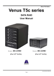
Model: DS-2250J
Venus T5 mini
2.5” SATA RAID
User Manual
www.amselectronics.com
1
Model: DS-2250J
Contents
1. Features ….......................................................................................................................3
2. DIP Switch and RAID Mode cross reference.................................................................5
2.1 RAID 0 for High Performance..........................................................................................7
2.2 RAID 1 (Mirror) for High Security....................................................................................7
2.3 Stripe + Mirror (RAID 10) for High Performance and High Security............................7
2.4 Clone.................................................................................................................................8
2.5 JBOD (Concatenating).....................................................................................................8
2.6 Parity Protection...............................................................................................................9
2.7 Normal Mode (Single).......................................................................................................9
2
Model: DS-2250J
1. Features
z
z
z
z
z
z
z
z
z
All Aluminum design
Plug & play, hot swappable
Support Windows, Mac & Linux
Built-in DIP Switch RAID mode setting
LED indicators (for AC Power, HDD Error, HDD Access)
Double Security handle lock
Port Multiplier -- support up to 5 x 2.5” SATA HDD
Built-in JMB393 Hardware RAID controller
Transfer rate: SATA 1.5Gb/s、SATA 3Gb/s
z
z
z
5 X 5 cm FAN X1— super air ventilation
Buzzer Alarm for overheating
Color: Black
z
z
z
20W, AC 100~240V, 50/60Hz
Dim: 5.5(L) X 3.1(W) X 4.9(H) inches
Weight: 1.35 lbs (enclosure only)
Figure 1
Figure 2
3
Model: DS-2250J
--- Front Panel--- (See Figure 3)
Front Panel Description:
A1 ~ A5 :Front panel “Push-Open” Button
a) Function: Push forward to open the front
HDD front panel.
b) LED Indication:
See LED Status description on page 5 & 6.
A 6: Power/System LED
Power on Æ Solid blue
Power off Æ No indication
A7: Mechanical lock :
To Open or Lock the front panels.
Note:
When push It to “un-lock” position, you can
open the front panels by pressing the
“push-Open button. While it is in the “lock”
position, the 5 front panels are locked and
cannot be open when you press the
“push-open” button.
Note: Do not try to press down the
“push-open button while it is locked.
Any inappropriate use of it may cause
the damage of the mechanical lock.
A8: Front Panel
4
Model: DS-2250J
--Rear View--- (see Figure 4)
Rear Parts Description:
B1: Power Input (+5V
B2: E-SATA port
B3: Raid Setting DIP Switch
4A )
(*7 Raid Mode: Raid 0, 10, 3, 5, JBOD, Single, Clone)
B4: Reset Device / Change Mode Button
1. Reset Device: Press it less than 2 seconds
2. Change Mode: Press it over 2 seconds
B5: Buzzer Disable Button / Power Switch
Button
1. Buzzer disable : Press it less than 2 seconds
2. Power Switch
: Press it over than 2 seconds
B6:Air ventilation holes
Figure 4
---LED Status--LED indicator(HDD0-HDD4)
[see figure 3, A1~A5]
Action
Light On
Message
Hard Drive Installed
color
Blue
Light Off
Hard Drive uninstalled
No
Light On
Hard Drive Fail
Red
Flash
Hard Drive Access
Blue
Power / System LED Indicator
[see figure 3, A6]
Light On
Power starting
Blue
Light On
System is ready
Purple
Light Off
Power is OFF
No
5
Model: DS-2250J
Raid Status
RAID10
RAID3
RAID5
JBOD (Large)
Clone
RAID 0(Single)
LED Indicator
[see figure 3, A1~A5]
Access
Blue/Flash
rebuilding
Blue & Red/Flash
Access
Blue/Flash
rebuilding
Blue & Red /Flash
Access
Blue/Flash
rebuilding
Blue & Red /Flash
Access
Blue/Flash
Access
Blue/Flash
Clone
Blue & Red /Flash
Access
Blue/Flash
2. DIP Switch and RAID Mode cross reference
User can configure any RAID mode as below by DIP switch setting and apply the change by
pressing the Change-Mode-Switch.
Note: When DIP Switch is set to RAID 10 ---*If you installed two HDD only, it is with RAID 1 mode
*If you installed four HDD, then, it is RAID 10 mode
2.1 RAID 0 for High Performance
RAID 0(or Stripe) is the segmentation of logically sequential data, such as a single file, so that
6
Model: DS-2250J
segments can be assigned to multiple hard disks in a round-robin fashion and thus written
concurrently. (If any one hard disk gets defective, information stored in this RAID 0 mode will be
invalid.)
2.2 RAID 1 (Mirror) for High Security
RAID 1 (or Mirror) is the replication of data onto separate hard disks in real time to ensure
continuous availability. Take a RAID 1 system with two hard disks as an example, data in a hard
disk will be exactly the same as the data in another hard disk.
(Failure in a hard disk, Host controller still could read/write data. Users have to replace the
defective hard disk. The device enclosure will enter identical-rebuild mode automatically)
2.3 Stripe + Mirror (RAID 10) for High Performance and High Security
The Raid Enclosure could be configured to support Stripe and Mirror at the same time, i.e. RAID
10. Take four hard drives RAID 10 as an example, hard drive 0 and hard drive 1 could act as
Mirror 1 and hard drive 2 and hard drive 3 could act as Mirror 1 too. Then, the Raid Enclosure
configures these two Mirrors as Stripe.
7
Model: DS-2250J
2.4 Clone
This mode is useful especially when users would like to copy data from a hard drive to several
hard drives at the same time. Clone’s action is similar to RAID 1. However, all of the hard disks
will be the mirrors. For example, in a four hard drives Clone environment, data in each hard
drive will be the same.
2.5 JBOD (Concatenating)
This mode is also named Concatenating. In this mode, the Raid Enclosure will concatenate all of
the hard drives into a single hard drive with larger capacity. For example, if three 1TB hard disks
are connected to the Raid Enclosure in concatenating mode, user will get a single hard disk with
capacity of 3TB capacity.
2.6 Parity Protection
8
Model: DS-2250J
XOR engine in the Raid Enclosure generates parity block. In RAID 3 mode, Parity Block will be
stored in the same hard drive. While in RAID 5 mode, Parity Block will be spread over all of the
different hard drives.
The Raid Enclosure will also make use of same size disk space in each hard disk under RAID 3(or
RAID 5) condition. (In RAID 3 or 5 modes, failure in a hard disk will cause the RAID Enclosure to
enter degraded-mode. Host controller still could read/write data through the Raid Enclosure
normally without knowing any defects. Users have to replace the defective hard disk. The Raid
Enclosure then will enter identical-rebuild mode automatically.)
2.7 Normal Mode (Single)
Normal mode means all of the configured hard drives exist and the Raid Enclosure is not in
rebuild condition. Users can see the original hard drives from the host which supports port
multiplier technology.
(Note: If the host controller does not support Port Multiplier function, only one hard drive
on the operating system will be detected. The RAID tool is useful in this case.)
9