1
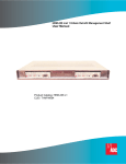
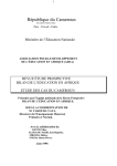
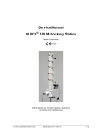
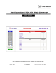
Ethernet Network Interface Unit (ENIU)
User Manual
20383-A1
ENIEG X
XEG
XX1B
Product Catalog: ENI-EGXXEGXX1B
Document Number: AIWN-UM-7001-01
CLEI: IPUIAY5F~~
REVISION HISTORY
The Revision History provides a summary of any changes in this manual. Please make sure you are using the
latest revision of this manual.
August 7, 2006
Revision
01
Release Date
August 7, 2006
Revisions Made
Initial release with new format.
Replaces ADCP-92-061 (Issue 1)
(1315502).
This manual is available online at ADC’s website (www.adc.com/documentationlibrary/) or you can order copies
of the manual by contacting your sales representative. Please ask for document AIWN-UM-7001-01.
Copyright
©2006 ADC Telecommunications, Inc. All rights reserved.
Trademark Information
ADC is a registered trademark of ADC Telecommunications, Inc. No right, license, or interest to such trademarks is granted
hereunder, and you agree that no such right, license, or interest shall be asserted by you with respect to such trademark.
Other product names mentioned in this practice are used for identification purposes only and may be trademarks or registered trademarks of their respective companies.
Disclaimer of Liability
Information contained in this document is company private to ADC Telecommunications, Inc., and shall not be modified,
used, copied, reproduced or disclosed in whole or in part without the written consent of ADC.
Contents herein are current as of the date of publication. ADC reserves the right to change the contents without prior notice.
In no event shall ADC be liable for any damages resulting from loss of data, loss of use, or loss of profits, and ADC further
disclaims any and all liability for indirect, incidental, special, consequential or other similar damages. This disclaimer of
liability applies to all products, publications and services during and after the warranty period.
Table of Contents
Chapter 1: Overview ....................................................................................................... 1-1
Product Description .................................................................................................................. 1-1
Front Panel ............................................................................................................................... 1-2
Chapter 2: Installation .................................................................................................... 2-1
Desktop Installation .................................................................................................................. 2-1
Surface Mount Installation ........................................................................................................ 2-1
Power and Ground Connections .............................................................................................. 2-2
Ground Connection ............................................................................................................ 2-2
Power Connection .............................................................................................................. 2-3
Cabling ..................................................................................................................................... 2-4
RJ-45 Ethernet Cables ....................................................................................................... 2-4
Optical Cables .................................................................................................................... 2-5
DB-9 Communications Cable ............................................................................................. 2-6
Chapter 3: Command-Line Interface (CLI) ................................................................... 3-1
Command Prompt .................................................................................................................... 3-1
Set-Up ...................................................................................................................................... 3-1
Commands Overview ............................................................................................................... 3-2
Security .................................................................................................................................... 3-2
Initial Set-up ............................................................................................................................. 3-2
Commands List ........................................................................................................................ 3-2
Help Commands ................................................................................................................ 3-2
Configuration ...................................................................................................................... 3-3
OAM Configuration ............................................................................................................. 3-5
Performance and Alarms ................................................................................................... 3-7
System Commands ............................................................................................................ 3-8
Appendix A: Specifications ......................................................................................... A-1
Appendix B: Product Support ..................................................................................... B-1
Glossary ......................................................................................................................GL-1
AIWN-UM-7001-01
iii
Table of Contents
iv
August 7, 2006
AIWN-UM-7001-01
List of Figures
Figure 1-1.
Figure 1-2.
Figure 2-1.
Figure 2-2.
Figure 2-3.
Figure 2-4.
Figure 2-5.
Figure 2-6.
ENIU with SFPs ................................................................................................ 1-1
ENIU Front View ............................................................................................... 1-2
Inserting ENIU into Mounting Bracket .............................................................. 2-2
ENIU Rear View with RJ-45 Connector ............................................................ 2-3
Four-Pin Power Plug Wiring Diagram .............................................................. 2-3
ENIU Front View with RJ-45 Connector ........................................................... 2-4
RJ-45 Connector Wiring ................................................................................... 2-4
9-Pin D-Sub Connector .................................................................................... 2-6
AIWN-UM-7001-01
v
List of Figures
vi
August 7, 2006
AIWN-UM-7001-01
List of Tables
Table 1-1. ENIU LED Indicators and Controls ...................................................................... 1-2
Table 2-1. 10/100 Mbps Ethernet RJ-45 Connector ............................................................. 2-5
Table 2-2. 1000BaseT Ethernet RJ-45 Connector ............................................................... 2-5
Table 2-3. EIA-232 DCE Control Connector (Female 9-Pin D-Sub) .................................... 2-6
Table 2-4. EIA-232 Serial Port Default Settings ................................................................... 2-6
Table 3-1. CLI Command Prompts ....................................................................................... 3-1
Table A-1.Ethernet NIU Specifications ................................................................................A-1
AIWN-UM-7001-01
vii
List of Tables
viii
August 7, 2006
AIWN-UM-7001-01
ABOUT THIS MANUAL
INTRODUCTION
This manual applies to ADC’s Ethernet Network Interface Unit (ENIU) card (hereafter referred to as the “ENIU”).
ORGANIZATION
This manual includes the following chapters:
Chapter
Description
Chapter 1: Overview
Summarizes the features and functionality provided with the
ENIU card.
Chapter 2: Installation
Provides procedures for installing an ENIU card.
Chapter 3: Command-Line Interface (CLI)
Lists the commands used to operate an ENIU card.
Appendix A: Specifications
Provides physical specifications for the ENIU, including power,
mechanical, environmental, and electrical requirements.
Appendix B: Product Support
Provides information on how to contact the ADC Technical
Support group.
INTENDED AUDIENCE
This manual is intended for anyone needing to operate, administer, or maintain ADC’s line of ENIU cards.
CONVENTIONS
The following style conventions and terminology are used throughout this guide.
Element
Meaning
Bold font
Text that you must input exactly as shown (e.g., type 1 for card 1), menu buttons
(e.g., ACCEPT SHELF OPTIONS) or menu screen options (e.g., ALARMS screen) that
you must select
Italic font
Variables that you must determine before inputting the correct value (e.g., Password )
Monospace font
References to screen prompts (e.g., Invalid Password...Try Again:.)
Reader Alert
Meaning
Alerts you to supplementary information
IMPORTANT
Alerts you to supplementary information that is essential to the completion of a task
!
Alerts you to possible equipment damage from electrostatic discharge
ATTENTION
CAUTION
AIWN-UM-7001-01
Alerts you to possible data loss, service-affecting procedures, or other similar type
problems
ix
About This Manual
August 7, 2006
Reader Alert
WARNING
DANGER
Meaning
Alerts you that failure to take or avoid a specific action might result in hardware damage or
loss of service
Alerts you that failure to take or avoid a specific action might result in personal harm
INSPECTING YOUR SHIPMENT
Upon receipt of the equipment:
• Unpack each container and visually inspect the contents for signs of damage. If the equipment has been damaged in transit, immediately report the extent of damage to the transportation company and to ADC. Order
replacement equipment, if necessary.
• Check the packing list to ensure complete and accurate shipment of each listed item. If the shipment is short
or irregular, contact ADC as described in Appendix B: Product Support on page B-1. If you must store the
equipment for a prolonged period, store the equipment in its original container.
x
AIWN-UM-7001-01
Chapter 1
OVERVIEW
PRODUCT DESCRIPTION
Delivering a comprehensive set of Ethernet services requires an intelligent Ethernet network interface unit (ENIU) to
serve as the service demarcation point at the edge of the customer's network. A critical component of a carrier-class
Ethernet access system, the ENIU defines the edge of the carrier's management domain. Once in place, the ENIU
serves an important function by collecting local performance and error data on both the access loop and the
customer's network.
Operations Administration and Maintenance (OAM), sub-layer defined by IEEE 802.3ah is intended to facilitate
management of Ethernet for subscriber access networks. The ENIU is designed to allow the carrier to segregate,
isolate and troubleshoot network problems remotely through use of the OAM Protocol Data Units (PDU). The ENIU
provides the following capabilities:
• One Ethernet Network Port
• One Ethernet Subscriber Port
• Full 802.3ah OAM functionality
• Enhanced OAM features provided via organization specific extension OAM PDU's
• Firmware that provides:
– Bandwidth Allocation
– Daily performance history log access
– 15 minute performance history log access
• One RS-232 console port to provide a command line interface to all of the management, status, and maintenance functions of the ENIU
• Local and Remote Field Software download
The ENIU provides interfaces for Central Office (Network) and Subscriber Ethernet through Small Form-factor
Pluggable (SFP) modules and/or RJ-45 connectors. RS-232 craft port interface is provided through a DB-9
connector. Power is supplied through a connector located on the rear. A front and rear view of the ENIU with SFPs
is shown in Figure 1-1.
ENI-
EGX
XE
21060-A1
GXX
1B
FRONT VIEW
REAR VIEW
Figure 1-1. ENIU with SFPs
AIWN-UM-7001-01
1-1
Chapter 1: Overview
August 7, 2006
FRONT PANEL
Each ENIU has three LEDs, a STATUS LED, a LPBK LED, and a LOS/LINK LED. Under normal operation the ENIU
STATUS LED is green. Front panel indicators and controls are defined in Table 1-1 on page 1-2. An ENIU is shown
in Figure 1-2.
ENI-EGXXEGXX1B
20476-A1
-
Figure 1-2. ENIU Front View
Table 1-1. ENIU LED Indicators and Controls
SIGNAL
STATUS
LPBK
LOS/ Link
COLOR
STATUS
GREEN
ENIU Power OK and operating properly.
RED
A service affecting fault exists within the ENIU.
OFF
ENIU Power OFF.
GREEN
Flashing if loopback is active on the ENIU.
OFF
No active loopback detected.
RED
LOS detected on the network or subscriber interface.
OFF
Normal operation.
CONTROL
DESCRIPTION
Reset
Pressing the reset button restarts the ENIU.
LPBK
Manual switch to enable or disable loopback at the ENIU.
1-2
AIWN-UM-7001-01
Chapter 2
INSTALLATION
When using the mounting bracket, allow six inches (15.3 cm) on both ends of the ENIU for cable access. Install the
ENIU using the following procedures.
DESKTOP INSTALLATION
Step
Action
1
Remove the protective adhesive backing from the four feet. Position a foot on each bottom corner of the
ENIU. Press these firmly onto the ENIU.
2
Situate the ENIU in a way that provides both front and rear access. LEDs and Ethernet connections are
located on both ends. Power connection is located on the rear panel.
3
Connect the power supply to the DC IN connector located on the back of the ENIU:
– If using AC power, connect the power supply to the AC source (110 – 240 VAC, 50 – 60 Hz).
– If using DC power, connect the power following local practices. (See “Power and Ground
Connections” on page 2-2.) See Appendix A: Specifications for fuse size.
4
Verify that the STATUS LED is lit.
DANGER
Infrared radiation is invisible and can seriously damage the retina of the eye. Do not look into the
optical connector of an operational transmitter, or into the end of an active fiber. A clean,
protective cap or hood MUST be immediately placed over any radiating connector or optical fiber
to avoid exposure to potentially dangerous amounts of radiation. This practice also helps prevent
contamination of connectors and adapters. Do not assume laser power is turned off or the fiber
is disconnected at the other end.
SURFACE MOUNT INSTALLATION
An optional ENIU mounting bracket provides a number of options when securing the ENIU to a vertical or horizontal
surface. An ENIU can be installed facing up, down, right, or left when mounted on a vertical surface. The same
mounting bracket is also used to secure the ENIU to the bottom of a work surface.
Note: Allow six inches (15.3 cm) on both ends of the ENIU for cable access.
Step
Action
1
Situate the ENIU in a way that provides both front and rear access. LEDs and Ethernet connections are
located on both ends. Power connection is located on the rear panel.
2
Using the mounting bracket as a template, mark and drill holes in the mounting surface.
3
Secure the mounting bracket to the surface with appropriate fasteners for the surface material (#10 wood
screws or machine screws depending on the mounting surface).
4
Align the slots on the rear face of the ENIU with the mounting bracket. See Figure 2-1. Slide the ENIU
into the mounting bracket.
5
If not already installed, insert SFP into ENIU until you hear it click in place.
AIWN-UM-7001-01
2-1
Chapter 2: Installation
August 7, 2006
Step
Action
6
Connect the power supply to the DC IN connector located on the back of the ENIU.
– If using AC power, connect power supply to the AC source (110 – 240 VAC, 50 – 60 Hz).
– If using DC power, connect power following local practices. (See “Power and Ground
Connections” on page 2-2.) See Appendix A: Specifications for fuse size.
7
Verify that the STATUS LED is lit.
20384-A1
ENI-
EGX
XEG
XX1B
Figure 2-1. Inserting ENIU into Mounting Bracket
POWER AND GROUND CONNECTIONS
Power and ground connections are located on the back of the ENIU.
DANGER
WARNING
To avoid the possibility of severe and potentially fatal electric shock, use extreme care when
working with the power terminations at the back of the ENIU.
Before making any connections to a ENIU, verify that the power is off (unplugged or fuse
removed at the fuse and alarm panel).
Ground Connection
To assure proper operation, the ground stud located on the back of the ENIU (see Figure 2-2 on page 2-3) should
be connected to a good earth ground. There must be no switching or disconnecting devices in the grounding circuit
conductor between the ENIU and the point of connection to the grounding electrode conductor.
This procedure establishes a connection between the ENIU and a ground connection. A frame ground termination
(#8 screw) is provided on the back of the ENIU for a frame ground connection. This connection must be made in
accordance with all local and national electrical codes. The ENIU should be connected directly to a grounding
electrode conductor or to a bonding jumper from a grounded electric box.
2-2
AIWN-UM-7001-01
August 7, 2006
Chapter 2: Installation
Step
Action
1
Using AWG 16 (1.25mm) solid copper wire, connect one end of the ground wire to the ground stud at the
back of the ENIU (shown in Figure 2-2 on page 2-3). Tighten the stud nut to 15 pound-force inches (1.7
Newton meters) of torque.
2
To assure proper operation, the ground stud must be connected to a good earth ground.
3
Connect the other end of the ground wire to the office ground conductor. Ensure this connection is made
using methods and hardware that meets all applicable local and national electrical codes.
20382-A
Figure 2-2. ENIU Rear View with RJ-45 Connector
Power Connection
RTN -48 VDC
POWER SOURCE
A
-48 VDC-B
RETURN-B
-48 VDC-A
RETURN-A
Following local practices, attach two pair of power supply wires from two separate power sources to the four pin
power plug (pair 1: -48 VDC-A, RETURN-A and pair 2: -48 VDC-B, RETURN-B) on the chassis backplane (see
Figure 2-3 for details).
RTN -48 VDC
POWER SOURCE
B
20477-A
Figure 2-3. Four-Pin Power Plug Wiring Diagram
Separately fuse each -48 VDC power source, but do not install fuses now. Recommended wire size is 20 AWG
(0.8 mm). This recommendation applies to wiring from the ENIU to a fuse panel using solid conductors. Fuse size
should not exceed recommendation (see Appendix A: Specifications for fuse size). Plug the power plug into the
power connector located on the back of the ENIU.
AIWN-UM-7001-01
2-3
Chapter 2: Installation
August 7, 2006
CABLING
RJ-45 cable connections are made to both the front and rear of the ENIU. DB-9 (command line interface) connection
is made on the front and the power connection is made on the rear. A rear view of the ENIU is shown in Figure 2-2
on page 2-3. A front view is provided below in Figure 2-4.
20383-A1
ENIEG X
XEG
XX1B
Figure 2-4. ENIU Front View with RJ-45 Connector
RJ-45 Ethernet Cables
Step
Action
1
Each ENIU has an RJ-45 connector located on the front and rear. Use this connector when making the
copper Ethernet connections. If an RJ-45 Patchcord is provided, proceed to Step 2. The following steps
describe how to make your own RJ-45 Patchcord. Pinout information is shown in Table 2-1 on page 2-5,
Table 2-2 on page 2-5, and Figure 2-5.
PIN 1
PIN 8
RJ-JACK
11899-A
Figure 2-5. RJ-45 Connector Wiring
a. Use Cat5e or better cable, strip back cable jacket to expose the four wire pairs, the metallic sheath,
and drain wire (if present).
b. Cut off metallic sheath and drain wire (if present) so that it is even with the outer jacket of the cables.
c. IEEE Specification for Ethernet 10 or 100BaseT(X) requires that two twisted pairs be used and one
pair is connected to pins 1 and 2, and the second pair is connected to pins 3 and 6.
d. IEEE Specification for Ethernet 1000BaseT requires that four twisted pairs are used. One pair is
connected to pins 1 and 2, pair two is connected to pins 3 and 6, pair three is connected to pins 4
and 5, and pair four is connected to pins 7 and 8.
2
2-4
Connect Ethernet RJ-45 patchcords to the corresponding receptacles on the ENIU.
AIWN-UM-7001-01
August 7, 2006
Chapter 2: Installation
Table 2-1. 10/100 Mbps Ethernet RJ-45 Connector
Pin #
Signal Name
Function
Pin #
Signal Name
Function
1
TX+
Transmit Data
2
TX–
Transmit Data
3
RX+
Receive Data
4
---
Not used
5
---
Not used
6
RX–
Receive Data
7
---
Not used
8
---
Not used
Table 2-2. 1000BaseT Ethernet RJ-45 Connector
Pin #
Signal Name
Function
Pin #
Signal Name
Function
1
BD1+
Bidirectional
2
BD1–
Bidirectional
3
BD2+
Bidirectional
4
BD3+
Bidirectional
5
BD3–
Bidirectional
6
BD2–
Bidirectional
7
BD4+
Bidirectional
8
BD4–
Bidirectional
Optical Cables
The maximum cable length is the cable length that the signal can travel without suffering from critical
attenuation (degradation).
The maximum distance that any optical link can support is dependent upon attenuation and dispersion at a
particular wavelength, maximum bit rate, receiver sensitivity, splice and connector loss, and the data rate used.
Refer to SFP specifications for operating parameters.
AIWN-UM-7001-01
2-5
Chapter 2: Installation
August 7, 2006
DB-9 Communications Cable
An RS-232 Craft port is provided through a DB-9 connector. Refer to your work order to determine the required
communications connections. After determining the required connections, make the necessary connection.
Shielded cable is recommended and the maximum cable length is 50 feet. A 1:1 cable is required to connect this
port to the male DTE com port of a PC. Pinout information is shown in Table 2-3 and Figure 2-6.
Table 2-3. EIA-232 DCE Control Connector (Female 9-Pin D-Sub)
Pin #
Signal Name
I/O
Function
1
---
-
Not used
2
TXD
O
Transmit Data
3
RXD
I
Receive Data
4
---
-
Not used
5
GND
6
---
-
Not used
7
---
-
Not used
8
---
-
Not used
9
---
-
Not used
Signal Ground
5
1
9
6
10868-A
Figure 2-6. 9-Pin D-Sub Connector
EIA-232 Communication Port Defaults
Host terminal or computer communication parameters must match the ENIU communication settings, see Table 2-4
for default settings.
Table 2-4. EIA-232 Serial Port Default Settings
Communication Parameter
Default
Baud Rate
115200
Data Bits
8
Parity
0
Stop Bits
1
No flow control
2-6
AIWN-UM-7001-01
Chapter 3
COMMAND-LINE INTERFACE (CLI)
This section lists the commands used to operate the ENIU. After the initial installation of an ENIU, most testing and
local operations are conducted with the Command Line Interface through a VT-100 compatible terminal. This
terminal is connected to the front panel of the ENIU, and provides a standard EIA-232C interface.
Note: Command keywords are not case-sensitive.
COMMAND PROMPT
The CLI provides a prompt with a character indicating the user’s privilege level.
Table 3-1. CLI Command Prompts
Effective privilege
Prompt
RO
command $
RW
command %
SECURE
command #
SET-UP
The ENIU requires minimal set-up to provide OAM PDU reception, reporting, and remote loop-back functionality.
The ENIU is shipped with a power supply connector, and a serial communications cable. The user must provide
network cables (Cat5e or better Ethernet cables for electrical interfaces or optical cables appropriate to the SFP for
optical connections). A PC with HyperTerminal or equivalent is required with an available COM port for status
monitoring. Follow these steps to connect the unit:
Step
Action
1
Connect Ethernet and/or optical cables to the desired equipment.
2
Connect the serial communications cable to the Command port of the ENIU and to any COM port on the
local PC.
3
Launch HyperTerminal and configure it for 115200 bits per second, 8 data bits, 0 parity bits, 1 stop bit,
and no flow control.
4
Connect the power supply to the appropriate connector on the ENIU.
5
Verify that the terminal displays a configuration screen.
AIWN-UM-7001-01
3-1
Chapter 3: Provisioning
August 7, 2006
COMMANDS OVERVIEW
All settings are immediately saved. There is no separate ‘save’ command. Some settings (for example, save
download) do not take effect until after the next CPU reset. The CLI will signal when a reboot is necessary.
Keyword tab completion and online help is available. Command-line editing and history is also available by using the
arrow keys as defined on most modern key boards.
General command format is:
<verb> <object> <parameters>
where <verb> is GET, SET, CLEAR, HELP, or RESET.
All parameter strings (user passwords and names) have a maximum of 15 characters.
SECURITY
Three types of users (privileges) are supported:
• Read-only (RO) users may only view non-sensitive performance and configuration information.
• Read-write (RW) users may do and see whatever they want except user and software maintenance.
• Secure (SECURE) users may do and see whatever they want including user and software maintenance.
Users have 3 attributes: username, user privilege (RO, RW, SECURE), and password. A maximum of 8 configurable
user definitions is supported. There is also a default user that is always present to provide RO access to the system.
Note: The default username is adc with a password of eniu.
If no users are defined, the system will allow full SECURE access from the Craft port, but once a configured user is
defined, you must log in with that user or the default user to access the system. When defining users, the system
ensures that there is always at least one SECURE user defined.
INITIAL SET-UP
The ENIU should be fully configured to work in your network without further configuration. It is strongly suggested
that usernames be defined to control ENIU access.
COMMANDS LIST
Help Commands
Purpose:
Shows supported CLI commands.
Commands [all privileges]:
HELP
HELP CLEAR
HELP GET
HELP SAVE
HELP SET
3-2
AIWN-UM-7001-01
August 7, 2006
Chapter 3: Provisioning
Configuration
Get Configuration
Purpose:
Show the current configured parameters.
Command:[all privileges]
GET CONFIGURATION
Interface Speed and Negotiation
Purpose:
Configure speed and negotiation mechanism for the NETWORK and SUBSCRIBER interfaces.
Command:[RW, SECURE privilege]
SET [NETWORK|SUBSCRIBER] INTERFACE SPEED 10|100|1000 [AUTO|FORCE]
Note: NETWORK or SUBSCRIBER is optional and is specified to identify a specific interface. If not
specified, both interfaces will be targeted. AUTO or FORCE is optional and indicates whether the
interface(s) should auto-negotiate up to the configured speed or if the interface should be forced to the
indicated speed. Negotiation defaults to AUTO if not specified.
Example 1: SET INTERFACE SPEED 100
Example 2: SET NETWORK INTERFACE SPEED 1000 FORCE
Status Commands: [all privileges]
GET CONFIGURATION
Configure Data Rate
Purpose:
Configure transmit and receive data rates relative to the SUBSCRIBER interface and independent of the link speed.
This mechanism provides a mechanism to limit the amount of bandwidth that the SUBSCRIBER can use.
Command:[RW, SECURE privilege]
SET [TRANSMIT|RECEIVE] DATA RATE FULL|<value>
TRANSMIT or RECEIVE is optional and is specified to identify a specific direction. If not specified, both directions
will be targeted. The data rate is specified in megabits by supplying a <value> number from 1 to 1000, or FULL to
allow the full rate of the interface.
Example: SET DATA RATE FULL
Example: SET TRANSMIT DATA RATE 15
Status Commands: [all privileges]
GET CONFIGURATION
AIWN-UM-7001-01
3-3
Chapter 3: Provisioning
August 7, 2006
Configure Keep Alive
Purpose:
Configure “keep alive” mode. When on, the ENIU will not generate an alarm event if the subscriber interface loses
link. This allows the network side to remain unencumbered by interfaces changes that may occur on the subscriber
port from random changes in the subscribers network.
Command:[RW, SECURE privilege]
SET KEEP ALIVE ON|OFF
Status Commands: [all privileges]
GET CONFIGURATION
Configure Loopback Operation
Purpose:
Configure Loopback settings and timeout values. The ENIU provides an extension to IEEE 802.3ah loopback
operation by providing a timeout feature. When on, loopback operations will automatically end after the timeout
period has elapsed and return the ENIU to normal state of passing data. Timeout values are specified in minutes
ranging from 10 to 240 minutes or 0 to disable the timeout. The ENIU implements OAM and extended OAM
methods of loopback operation as well as manual operation through the command line and a push button.
Command:[RW, SECURE privilege]
SET LOOPBACK TIMEOUT <minutes>
SET LOOPBACK ON|OFF
Status Commands: [all privileges]
GET CONFIGURATION
GET LOOPBACK STATUS
Configure Error Forwarding Mode
Purpose:
Configure Error Forwarding mode to on/off. The ENIU provides the feature to forward the frames received with
errors to the other side for end to end testing. When on, frames received with errors are forwarded to the other side
and when set to off, the frames received with errors are discarded. The default is off.
Command:[RW, SECURE privilege]
SET ERROR FORWARDING ON/OFF
Status Commands: [all privileges]
GET CONFIGURATION
3-4
AIWN-UM-7001-01
August 7, 2006
Chapter 3: Provisioning
Craft Port Configuration
Purpose:
Configure user interaction with the command line interpreter.
Note: The Craft port interface has fixed communications settings of 115200 baud, 8 bits, 1 stop bit, no
parity, and no flow control.
Command:[RW, SECURE privilege]
SET IDLE TIMEOUT <minutes>
Identifies the number of minutes that the Craft port can remain idle before a logged in user is logged off.
Command:[all privileges]
SET ECHO ON|OFF
Controls character echo for the current session.
Status Commands: [all privileges]
GET CONFIGURATION
System Name
Purpose:
Configure the system name.
Command:[RW, SECURE privilege]
SET SYSTEM NAME <name>
CLEAR SYSTEM NAME
Status Commands: [all privileges]
GET CONFIGURATION
OAM Configuration
The ENIU supports standard IEEE 802.3ah OAM operation as well as several extensions that allow its functionality
to be used across a VLAN.
Configure OAM for IEEE 802.3ah Operation
Purpose:
Configure OAM to operate as an IEEE 802.3ah device.
Command:[RW, SECURE privilege]
SET OAM CONFIGURATION
Status Commands: [all privileges]
GET CONFIGURATION
AIWN-UM-7001-01
3-5
Chapter 3: Provisioning
August 7, 2006
Configure OAM for EXFO Operation
Purpose:
Configure OAM to interoperate with EXFO test equipment in a VLAN environment. Note: In addition to configuring
OAM extensions, this command also changes the MAC address from which OAM messages will be accepted from
the slow protocols address to an ADC unique multicast address of 01:80:51:00:00:00.
Command:[RW, SECURE privilege]
SET EXFO OAM CONFIGURATION
Status Commands: [all privileges]
GET CONFIGURATION
Configure OAM Mode of Operation
Purpose:
Configures OAM to operate in ACTIVE or PASSIVE mode or to turn OAM processing off.
Command:[RW, SECURE privilege]
SET OAM MODE ACTIVE|PASSIVE|OFF
Status Commands: [all privileges]
GET OAM STATUS
Configure OAM Extensions
Purpose:
Configure the individual OAM extensions that allow for OAM operation over a VLAN and for use with EXFO test
equipment.
Command:[RW, SECURE privilege]
SET DISCOVERY MODE ON|OFF
Turns on abbreviated discovery mode for use with EXFO test equipment.
SET SWAP ADDRESS MODE ON|OFF
When on, forces ENIU to swap the source and destination addresses and recalculate the frame check sequence
during loopback operations so that test frames can be returned directly to the sender.
SET UNICAST MODE ON|OFF
When on, forces the ENIU to send OAM messages to the unicast address of the active mode OAM peer that is
found during OAM discovery instead of sending messages to the slow protocols address.
SET VLAN MODE ON|OFF
When on, allows the ENIU to discover VLAN tagged OAM protocol messages during OAM discovery and then use
that tag to continue OAM protocol communications.
Status Commands: [all privileges]
GET CONFIGURATION
3-6
AIWN-UM-7001-01
August 7, 2006
Chapter 3: Provisioning
User and Privilege Settings
Purpose:
Defines users to the system.
Command: [SECURE privilege]
SET USER <name> RO|RW|SECURE <password>
CLEAR USER <name>
User name and passwords are specified as 1 to 15 alphanumeric characters.
Status Command: [SECURE privileges]
GET USERS
Performance and Alarms
Configure Alarm Thresholds
Purpose:
Configures the OAM alarm threshold and windows for CRC, Errored Symbol Period, Errored Frame Event, Errored
Frame Period, and Errored Frame Seconds Summary events.
Command: [RW,SECURE privilege]
SET [<interface>] <type> EVENT THRESHOLD <number> [WINDOW <number>]
• <interface> can optionally be specified to target a specific interface; when not specified, both interfaces are targeted. <interface> must be either NETWORK or SUBSCRIBER.
• <type> is one of CRC|FRAME|FRAME PERIOD|FRAME SECONDS|SYMBOL PERIOD.
• <number> is an integer value whose range is dependent on the <type> and interface speed as specified by
IEEE 802.3ah. For convenience, MINIMUM and MAXIMUM are keywords that can be substituted for <number>
to set the values to the minimum and maximum values specified in IEEE 802.3ah.
• [WINDOW <number>] can be optionally specified; if not specified, the pervious value is retained.
Example: SET FRAME PERIOD EVENT THRESHOLD 1
Example: SET SUBSCRIBER CRC EVENT THRESHOLD MINIMUM WINDOW MAXIMUM
Status Command: [all privileges]
GET [NETWORK|SUBSCRIBER] EVENT THRESHOLD
GET [NETWORK|SUBSCRIBER] ALARM STATUS
AIWN-UM-7001-01
3-7
Chapter 3: Provisioning
August 7, 2006
Configure Optical Thresholds
Purpose:
On ENIUs that have optical interfaces, these commands configure the alarm thresholds associated with the power
levels of the optical connections.
Command: [RW, SECURE privilege]
SET [NETWORK|SUBSCRIBER] OPTICAL RECEIVE THRESHOLD OMA|AVERAGE threshold
SET [NETWORK|SUBSCRIBER] OPTICAL TRANSMIT THRESHOLD OMA|AVERAGE threshold
The threshold value is specified in milliwatts.
Status command: [all privileges]
GET OPTICAL THRESHOLDS
Monitor Performance
Purpose:
View and reset 15 minute and daily performance totals.
Command:[RW, SECURE privilege]
CLEAR PERFORMANCE STATUS
Status Commands: [all privileges]
GET [DAY] PERFORMANCE STATUS
The 15-minute totals are displayed unless DAY is specified. Specifying DAY will cause the daily totals to be
displayed.
Interface Status
Purpose:
View link status and alarm conditions.
Command:[all privileges]
GET INTERFACE STATUS
System Commands
Temperature
Purpose:
Shows the internal operating temperature of the system.
Command: [all privileges]
GET TEMPERATURE
Optical Power
Purpose:
On ENIUs that have optical interfaces, this command shows the level of optical power being received.
Command: [all privileges]
GET NETWORK OPTICAL POWER
GET SUBSCRIBER OPTICAL POWER
3-8
AIWN-UM-7001-01
August 7, 2006
Chapter 3: Provisioning
Exit
Purpose:
Log off of a command line session.
Command: [all privileges]
EXIT
Inventory
Purpose:
Shows hardware and firmware versions as well as ADC catalog and part numbers.
Command: [all privileges]
GET INVENTORY
LED test
Purpose:
Perform an LED test for the front panel LEDs.
Command: [RW, SECURE privilege]
SET LED TEST
Reset
Purpose:
Restart the firmware in the ENIU.
Command: [RW, SECURE privilege]
RESET
Software Maintenance
Purpose:
Load new software.
Command:[SECURE privilege]
START DOWNLOAD
Starts the XMODEM protocol on the craft port to allow downloading of new firmware.
SAVE DOWNLOAD
Saves a successful firmware download so that it will become the operational software.
Status Commands: [all privileges]
GET DOWNLOAD STATUS
AIWN-UM-7001-01
3-9
Chapter 3: Provisioning
3-10
August 7, 2006
AIWN-UM-7001-01
Appendix A
SPECIFICATIONS
Specifications for the ENIU are listed in Table A-1.
Table A-1. Ethernet NIU Specifications
PARAMETER
SPECIFICATION
Remarks
Power
Voltage
–48VDC, or 110 to 240VAC (50–60 Hz)
Operating Voltage
+5 VDC
Backplane connector
Input Current
0.25 A maximum
Normal operation
Fuse Size
1.0 Amps
–48 VDC
Environmental
Operating Conditions
+23°F to +122°F (–5°C to +50°C) 5% to 90% RH
Storage Conditions
-40°F to +185°F (-40°C to +85°C) 10% to 95% RH
No Condensation
Mechanical
Dimensions D x W x H
1.55 in. × 4.25 in. × 9.09 in.
(3.94 cm × 10.8 cm × 23.1 cm)
Weight
1.8 lb. (0.81 kg.)
Electrical
Network Interface
RJ-45, SFP
Network Data Rates
Configurable to 10Mbps, 100Mbps or 1000Mbps
Customer Interface
RJ-45, SFP [Small Form-factor Pluggable (SFP)
Transceiver Multi-Source Agreement (MSA)]
Customer Data Rates
Configurable to 10Mbps, 100Mbps or 1000Mbps
Copper Media
Requirements
10Mbps UTP Category 3, 4, 5 or better
Two twisted pair
100Mbps UTP Category 5 or better
Two twisted pair
1000Mbps UTP Category 5e or better
Four twisted pair
328 feet (100 meters)
Copper
Distance
Optical Media Requirements 850 to 1550 nm
Distance
AIWN-UM-7001-01
Single Mode or Multi-Mode
fiber
Optical
The maximum distance that any optical link can
support is dependent upon attenuation and dispersion
at a particular wavelength, maximum bit rate, receiver
sensitivity, splice and connector loss, etc. Refer to SFP
specifications for operating parameters.
A-1
Appendix A: Specifications
A-2
August 7, 2006
AIWN-UM-7001-01
Appendix B
PRODUCT SUPPORT
ADC Customer Service Group provides expert pre-sales support and training for all of its products. Technical
support is available 24 hours a day, 7 days a week by contacting the ADC Technical Assistance Center.
Sales Assistance: 800.366.3891
Quotation Proposals, Ordering and Delivery General,
and Product Information
Systems Integration: 800.366.3891
Complete Solutions (from concept to installation),
Network Design and Integration Testing, System TurnUp and Testing, Network Monitoring (upstream or
downstream), Power Monitoring and Remote
Surveillance, Service/Maintenance Agreements, and
Systems Operation
ADC Technical Assistance Center:
800.366.3891
Technical Information, System/Network Configuration,
Product Specification and Application, Training
(product-specific), Installation and Operation
Assistance, and Troubleshooting and Repair/Field
Assistance
Email: [email protected]
Online Technical Support:
www.adc.com/Knowledge_Base/index.jsp
Online Technical Publications:
www.adc.com/documentationlibrary/
technicalpublications/
Product Return Department: 800.366.3891
ADC Return Material Authorization (RMA) number and
instructions must be obtained before returning products.
Email: [email protected]
AIWN-UM-7001-01
B-1
Appendix B: Product Support
B-2
August 7, 2006
AIWN-UM-7001-01
GLOSSARY
A
ALM – Alarm
AWG – American Wire Gauge
C
CLI – Command Line Interface
CO – Central Office
CPE – Customer Premise Equipment
E
ENIU – Ethernet Network Interface Unit
F
FCC – Federal Communications Commission
G
GND – Ground
L
LEC – Local Exchange Carrier
LED – Light-Emitting Diode
M
MON – Monitor
O
OAM – Operations, Administration, and Maintenance
OSS – Operations Support System
P
PDU – Protocol Data Units
R
RX – Receive
S
SFP – Small Form-factor Pluggable (SFP) Optical Transceiver Module
T
TX – Transmit
AIWN-UM-7001-01
GL-1
Glossary
GL-2
August 7, 2006
AIWN-UM-7001-01
Certification and Warranty
Limited Warranty
Product warranty is determined by your service agreement. Refer to the ADC Warranty/Software Handbook for
additional information, or contact your sales representative or Customer Service for details.
Modifications
The FCC requires the user to be notified that any changes or modifications made to this device that are not
expressly approved by ADC voids the user’s warranty.
All wiring external to the products should follow the provisions of the current edition of the National Electrical Code.
FCC Class A Compliance
This equipment has been tested and found to comply with the limits for a Class A digital device, pursuant to Part 15
of the FCC Rules. These limits are designed to provide reasonable protection against harmful interference when
the equipment is operated in a commercial environment. This equipment generates, uses, and can radiate radio
frequency energy and, if not installed and used in accordance with the instruction manual, may cause harmful interference to radio communications. Operation of this equipment in a residential area is likely to cause harmful interference in which case the user will be required to correct the interference at his own expense.
Safety Standards Compliance
This equipment has been tested and verified to comply with the applicable sections of the following safety standards:
• GR 63-CORE - Network Equipment-Building System (NEBS) Requirements
• GR 1089-CORE - Electromagnetic Compatibility and Electrical Safety
• Binational Standard, UL-60950 3rd Edition/CSA1459 C22.2 No. 60950-00: Safety of Information Technology
Equipment
For technical assistance, refer to “Appendix B: Product Support” on page B-1.
World Headquarters
ADC Telecommunications, Inc.
PO Box 1101
Minneapolis, MN 55440-1101 USA
For Technical Assistance
Tel: 800.366.3891
Ethernet Network Interface Unit (ENIU)
User Manual
Product Catalog: ENI-EGXXEGXX1B
Document Number: AIWN-UM-7001-01
´-R<¶6{¨
1350286