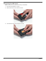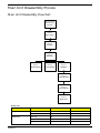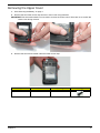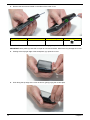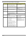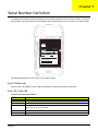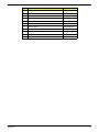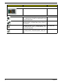
1
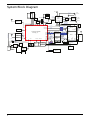
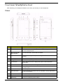
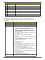
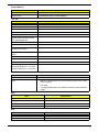
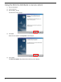
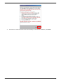
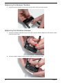
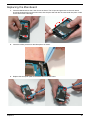
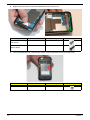
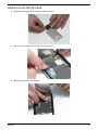
F900 Smartphone
Service Guide
Service guide files and updates are available
on the ACER/CSD web; for more information,
please refer to http://csd.acer.com.tw
PRINTED IN TAIWAN
Revision History
Please refer to the table below for the updates made on the F900 smartphone service guide.
Date
II
Chapter
Updates
Copyright
Copyright © 2009 by Acer Incorporated. All rights reserved. No part of this publication may be reproduced,
transmitted, transcribed, stored in a retrieval system, or translated into any language or computer language, in
any form or by any means, electronic, mechanical, magnetic, optical, chemical, manual or otherwise, without
the prior written permission of Acer Incorporated.
Disclaimer
The information in this guide is subject to change without notice.
Acer Incorporated makes no representations or warranties, either expressed or implied, with respect to the
contents hereof and specifically disclaims any warranties of merchantability or fitness for any particular
purpose. Any Acer Incorporated software described in this manual is sold or licensed "as is". Should the
programs prove defective following their purchase, the buyer (and not Acer Incorporated, its distributor, or its
dealer) assumes the entire cost of all necessary servicing, repair, and any incidental or consequential
damages resulting from any defect in the software.
Acer is a registered trademark of Acer Corporation.
Intel is a registered trademark of Intel Corporation.
Other brand and product names are trademarks and/or registered trademarks of their respective holders.
III
Conventions
The following conventions are used in this manual:
IV
SCREEN MESSAGES
Denotes actual messages that
appear on screen.
NOTE
Gives bits and pieces of additional
information related to the current
topic.
WARNING
Alerts you to any damage that might
result from doing or not doing
specific actions.
CAUTION
Gives precautionary measures to
avoid possible hardware or software
problems.
IMPORTANT
Reminds you to do specific actions
relevant to the accomplishment of
procedures.
Preface
Before using this information and the product it supports, please read the following general information.
1.
This Service Guide provides you with all technical information relating to the BASIC CONFIGURATION
decided for Acer's "global" product offering. To better fit local market requirements and enhance product
competitiveness, your regional office MAY have decided to extend the functionality of a machine. These
LOCALIZED FEATURES will NOT be covered in this generic service guide. In such cases, please contact
your regional offices or the responsible personnel/channel to provide you with further technical details.
2.
Please note WHEN ORDERING FRU PARTS, that you should check the most up-to-date information
available on your regional web or channel. If, for whatever reason, a part number change is made, it will
not be noted in the printed Service Guide. For ACER-AUTHORIZED SERVICE PROVIDERS, your Acer
office may have a DIFFERENT part number code to those given in the FRU list of this printed Service
Guide. You MUST use the list provided by your regional Acer office to order FRU parts for repair and
service of customer machines.
V
VI
Table of Contents
System Specifications
1
Features . . . . . . . . . . . . . . . . . . . . . . . . . . . . . . . . . . . . . . . . . . . . . . . . . . . . . . . . . . . .1
System Block Diagram . . . . . . . . . . . . . . . . . . . . . . . . . . . . . . . . . . . . . . . . . . . . . . . . .4
Your Acer Smartphone tour . . . . . . . . . . . . . . . . . . . . . . . . . . . . . . . . . . . . . . . . . . . . .5
Views . . . . . . . . . . . . . . . . . . . . . . . . . . . . . . . . . . . . . . . . . . . . . . . . . . . . . . . . . .5
Hardware Specifications and Configurations . . . . . . . . . . . . . . . . . . . . . . . . . . . . . . . .6
Software Upgrades
1
System Requirements . . . . . . . . . . . . . . . . . . . . . . . . . . . . . . . . . . . . . . . . . . . . . . . . .1
Mode Switching . . . . . . . . . . . . . . . . . . . . . . . . . . . . . . . . . . . . . . . . . . . . . . . . . . . . . .1
Performing a Soft Reset . . . . . . . . . . . . . . . . . . . . . . . . . . . . . . . . . . . . . . . . . . . .1
Switching to Download Mode . . . . . . . . . . . . . . . . . . . . . . . . . . . . . . . . . . . . . . . .1
Performing a Clean Boot. . . . . . . . . . . . . . . . . . . . . . . . . . . . . . . . . . . . . . . . . . . .1
Software Upgrade Procedure . . . . . . . . . . . . . . . . . . . . . . . . . . . . . . . . . . . . . . . . . . . .1
Using a BIN File (For service center only) . . . . . . . . . . . . . . . . . . . . . . . . . . . . . .1
Using the EUU (For distributor or service center) . . . . . . . . . . . . . . . . . . . . . . . . .2
Machine Disassembly and Replacement
1
Disassembly Requirements . . . . . . . . . . . . . . . . . . . . . . . . . . . . . . . . . . . . . . . . . . . . .1
Related Information . . . . . . . . . . . . . . . . . . . . . . . . . . . . . . . . . . . . . . . . . . . . . . . .1
General Information . . . . . . . . . . . . . . . . . . . . . . . . . . . . . . . . . . . . . . . . . . . . . . . . . . .1
Pre-disassembly Instructions . . . . . . . . . . . . . . . . . . . . . . . . . . . . . . . . . . . . . . . .1
Disassembly Process . . . . . . . . . . . . . . . . . . . . . . . . . . . . . . . . . . . . . . . . . . . . . .1
External Module Disassembly Process . . . . . . . . . . . . . . . . . . . . . . . . . . . . . . . . . . . .2
External Modules Disassembly Flowchart . . . . . . . . . . . . . . . . . . . . . . . . . . . . . .2
Removing the Stylus . . . . . . . . . . . . . . . . . . . . . . . . . . . . . . . . . . . . . . . . . . . . . . .3
Removing the Mini-SD Card . . . . . . . . . . . . . . . . . . . . . . . . . . . . . . . . . . . . . . . . .4
Removing the Back Cover . . . . . . . . . . . . . . . . . . . . . . . . . . . . . . . . . . . . . . . . . .6
Removing the Battery . . . . . . . . . . . . . . . . . . . . . . . . . . . . . . . . . . . . . . . . . . . . . .7
Removing the SIM Card . . . . . . . . . . . . . . . . . . . . . . . . . . . . . . . . . . . . . . . . . . . .8
Main Unit Disassembly Process . . . . . . . . . . . . . . . . . . . . . . . . . . . . . . . . . . . . . . . . . .9
Main Unit Disassembly Flowchart . . . . . . . . . . . . . . . . . . . . . . . . . . . . . . . . . . . . .9
Removing the Upper Cover . . . . . . . . . . . . . . . . . . . . . . . . . . . . . . . . . . . . . . . .11
Removing the LCD Module . . . . . . . . . . . . . . . . . . . . . . . . . . . . . . . . . . . . . . . . .16
Removing the Mainboard . . . . . . . . . . . . . . . . . . . . . . . . . . . . . . . . . . . . . . . . . .18
Removing the Vibration Module . . . . . . . . . . . . . . . . . . . . . . . . . . . . . . . . . . . . .21
Removing the Receiver Module . . . . . . . . . . . . . . . . . . . . . . . . . . . . . . . . . . . . .22
Removing the SIM Board . . . . . . . . . . . . . . . . . . . . . . . . . . . . . . . . . . . . . . . . . .23
Removing the Camera Shielding . . . . . . . . . . . . . . . . . . . . . . . . . . . . . . . . . . . .25
Removing the Camera Module . . . . . . . . . . . . . . . . . . . . . . . . . . . . . . . . . . . . . .26
Removing the Middle Cover . . . . . . . . . . . . . . . . . . . . . . . . . . . . . . . . . . . . . . . .27
Replacing Internal Module Components . . . . . . . . . . . . . . . . . . . . . . . . . . . . . . . . . . .28
Replacing the Middle Cover . . . . . . . . . . . . . . . . . . . . . . . . . . . . . . . . . . . . . . . .28
Replacing the Camera Module . . . . . . . . . . . . . . . . . . . . . . . . . . . . . . . . . . . . . .31
Replacing the Camera Shielding . . . . . . . . . . . . . . . . . . . . . . . . . . . . . . . . . . . .32
Replacing the SIM Board . . . . . . . . . . . . . . . . . . . . . . . . . . . . . . . . . . . . . . . . . .32
Replacing the Receiver Module . . . . . . . . . . . . . . . . . . . . . . . . . . . . . . . . . . . . .34
Replacing the Vibration Module . . . . . . . . . . . . . . . . . . . . . . . . . . . . . . . . . . . . .34
Replacing the Mainboard . . . . . . . . . . . . . . . . . . . . . . . . . . . . . . . . . . . . . . . . . .35
Replacing the LCD Module . . . . . . . . . . . . . . . . . . . . . . . . . . . . . . . . . . . . . . . . .37
Replacing the Upper Cover . . . . . . . . . . . . . . . . . . . . . . . . . . . . . . . . . . . . . . . . .38
Replacing Internal Module Components . . . . . . . . . . . . . . . . . . . . . . . . . . . . . . . . . . .40
Replacing the SIM Card . . . . . . . . . . . . . . . . . . . . . . . . . . . . . . . . . . . . . . . . . . .40
Replacing the Battery . . . . . . . . . . . . . . . . . . . . . . . . . . . . . . . . . . . . . . . . . . . . .41
VII
Table of Contents
Replacing the Back Cover . . . . . . . . . . . . . . . . . . . . . . . . . . . . . . . . . . . . . . . . .41
Replacing the Mini-SD Card . . . . . . . . . . . . . . . . . . . . . . . . . . . . . . . . . . . . . . . .42
Replacing the Stylus . . . . . . . . . . . . . . . . . . . . . . . . . . . . . . . . . . . . . . . . . . . . . .43
Diagnostics and Troubleshooting
1
Using DebugSwitcher Function Testing . . . . . . . . . . . . . . . . . . . . . . . . . . . . . . . . . . . .1
RUN IN and Discharge Tests . . . . . . . . . . . . . . . . . . . . . . . . . . . . . . . . . . . . . . . .1
FM Receiver, Audio and GPS1 Tests . . . . . . . . . . . . . . . . . . . . . . . . . . . . . . . . . .2
Camera Test . . . . . . . . . . . . . . . . . . . . . . . . . . . . . . . . . . . . . . . . . . . . . . . . . . . . .3
Function Testing 1 . . . . . . . . . . . . . . . . . . . . . . . . . . . . . . . . . . . . . . . . . . . . . . . .4
Function Testing 2 . . . . . . . . . . . . . . . . . . . . . . . . . . . . . . . . . . . . . . . . . . . . . . . .6
G Sensor and Light Sensor Tests . . . . . . . . . . . . . . . . . . . . . . . . . . . . . . . . . . . . .7
TV-out and GPS2 Test . . . . . . . . . . . . . . . . . . . . . . . . . . . . . . . . . . . . . . . . . . . . .8
Using the Windows Mobile Test System . . . . . . . . . . . . . . . . . . . . . . . . . . . . . . . . . . .9
Serial Number Definition
1
FRU (Field Replaceable Unit) List
1
F900 Smartphone Exploded Diagram . . . . . . . . . . . . . . . . . . . . . . . . . . . . . . . . . . . . .2
F900 Smartphone FRU List . . . . . . . . . . . . . . . . . . . . . . . . . . . . . . . . . . . . . . . . . . . . .4
Online Support Information
1
Index
1
VIII
Chapter 1
System Specifications
Features
Below is a brief summary of the smartphone’s many features:
Operating System
•
Windows Mobile® 6.1 Professional for Pocket PC Phone Edition
Processor
•
Samsung SC3 6410, 533 MHz with one DRAM
Memory
•
256 MB Flash ROM, 128 MB SDRAM
Display
•
3.8", 800 x 480 (VGA), 65,536 colors, TFT-LCD touch panel/window
Dimensions and Weight
•
117.5 (L) x 63.5 (W) x 12.9 (H) mm
•
155 g (including battery and stylus)
Communications
•
HSDPA / UMTS (2100/1900/850 MHz)
•
Quad-Bands GSM: 850/900/1800/1900 MHz
•
EDGE class 10/GPRS class 10
Wireless LAN
•
802.11b/g
Modem
•
EMP U365 (POP)
•
Embedded SiRF Star III chipset TMC function supported (subject to region availability)
GPS
Bluetooth
•
Chapter 1
Bluetooth 2.0 class 2+EDR
1
Camera
•
Built-in 3 mega pixels auto-focus CMOS camera with flashlight, up to 2048 x 1536 resolution
•
VGA resolution fixed-focus CMOS camera for video telephony usage
Light sensor
•
Sensing the brightness of environment to adjust panel luminance
•
Composite TV out
•
FM 76 ~ 108MHz, support Channel Search
TV-out
Radio
Expansion Options
•
MicroSD card slot
Interface/Audio
•
Built-in microphone and speaker, hands-free mode supported
Interface/Data
•
Mini USB Sync
Ergonomic Design
•
Touch panel for stylus or fingertip
•
Buttons:
•
Power button
•
Camera shutter key
•
Reset button
•
Record button
•
Volume control key
•
Send/End key
•
Quick Application key x 2 (GPS hotkey /TBD)
•
Gravity Sensor for user-friendly operation
•
DC Adaptor, 5V, 1A
Power
Battery
•
2
1530 mAh, rechargeable Lithium Polymer
•
Talk time: 3G: 4 hours, 2G: 6 hours (backlight off)
•
Standby: 245 hours (WDCDMA), 275 hours (GSM)
•
Pocket PC usage: 15 hours
•
GPS usage: 5 hours
Software (pre-loaded*)
•
Windows Mobile@ 6.1 Professional
•
Microsoft® Office Outlook Mobile (Calendar, Contacts, Tasks and Inbox)
•
Microsoft® Office Word Mobile / Microsoft® Office Excel Mobile / Microsoft® Office PowerPoint
Mobile
•
MSN® Messenger / Microsoft® Transcriber / Windows Media® Player 10
•
Picture / Notes / Internet Explorer Mobile / ActiveSync / Calculator / Game (Solitaire, Bubble
Breaker)
•
Microsoft Reader* (* depends on region)
Acer Exclusive Applications
•
User interface:
•
•
Phone Tools:
•
•
Image Maker, Multimedia Manager, Camera (Camcorder, Image Wizard), FM Tuner*
(*Subject to change by region)
Utilities:
•
•
Phone Application*, Phone Setting, SIM Toolkit, Speed Dial, Call Filter, Wireless Modem,
Wireless Manager, Dialer Skin, Add Ringtone, CSD Type, Voice Commander*, Connection
Wizard, SMS Sender, MMS Composer*, SIM Manager, Video Telephony, (*Subject to change
by region)
Multimedia Tools:
•
•
Acer Shell v2.0
Quick Link, Battery Meter, Zoom SMS, Bluetooth Manager, M-Desk, Scenario, Backup Utility,
Name card Manager
GPS Tools:
•
Satellite Data Update, Location SMS
3
System Block Diagram
MIC
Sharp 3.8"
WVGA
480x800
HS_L / R
IN1
I2C
BT PCM
SDIO_2
nTV_DET
TV
USB
K/B Fn
MEM Port0
MEM Port1
5
GSMRST
2
GPIO
GPIO
GPIO
HS SPI
UART0
I2C
CPU Debug UART
BT RX / TX
GPS RX / TX
CPLD IRQ
CPU IRQ
GSM RI
MODEM SPI
Gas-gauge
BQ27500
UART SWITCH
PWR
Management
&
Ext GPIO
4
6
ONSWAn
ONSWA
PWRRSTn_OUT
PWRRSTn
AB 3100
VPPFLASH
ACC_UART0
L3GACC_UART3
CPU_BT RX/TX
Ext Debug UART
Ext Download RX / TX
PWR key
Reset key
CWR_E
nTV_DET
MODEM SPI
PWR_EN_SYS
UART0
UART3
PCM
DB3210
RF
CWR_E
SPI
MEM I/F
OneDRAM A-port
32MB
NA ND Fl ash
I2C
MEM Port0
VBATT
SERVICEn_a
CPLD Jtag
CO NN
Action, Camera, Volume keys (Up / Down)
BATT LOW PWR, Reset key, AP key x4
TS
SIM
VDD_A/B/C/D
1
Jtag
2
LE D4
1
3
2
1
3
4
OT
Li-Polymer
1530mAH
Battery
4
CPLD X2C128
EULB
CE
OneDRAM B-port
32MB
3
EMP_BEAR
PWRRSTn
VIN
DER
USB
CONN
PMU
Charger
HS_L / R
Ext Download RX / TX
Ext Debug UART
USB ID
NAND Flash mDDR
64MB
256MB
G
S
NEERG
TV USB
D
LED Ctrl
Vcore
2.85V
3.3V
G
S
TV Signal
Ext Mic
PWR_EN_SYS
SI M
Sl ot
EMP_MIC
Et hernet Debug
Boar d
ABUSY_E
SDIO2
WiFi
GSMPWR
EMP_RESET
UART1
UART2
UART3
CPU_BT RX/TX
Reciver
WAKE
BT
D
EMP_ON/OFF
AWR_E
ABUSY_E
PCM
RCV_OUT + /-
MODEM PCM
GSM_REC + /GSM_MIC + /-
CLK, SYNC
SDIO_0
FM Audio
RCV_SW
AWR_E
FM ANT Signal
FM
0. 5W
Speaker
I2S
PCM
Samsung S3C6410
POP Ty pe
AMP
MAX9730
UART2
[video]
ABUSY_E
I2C
UART_3
SDIO 0
OUT3 IN4 PCMB PCMA
3M COMS
LCD B/L Ctrl LED Ctrl Camera I/F
GPIO
SPK + / OUT1 RCV+ / -
I2S
27MHz 32.768KHz
T/P
Micro SD Slot
IN2
CODEC
AK4671
) N(
48MHz 12MHz
I2C
I2S
LED
Driver
UART 3
GPS (HOST)
Flash Light
)N(
B/L
Driver
OUT2
FM Audio IN3
L Sensor
Touch Lens
US B
Ear phon e
EXT_MIC
G Sensor
Your Acer Smartphone tour
After examining your smartphone features, let us show you around your new smartphone.
Views
No.
Item
Description
1
Mini USB connector
Connect to a USB cable/headphones/ charger.
2
Power button
Press to turn the screen on/off or enter sleep mode; press and hold to
turn the smartphone off.
3
Bluetooth/WLAN/
GPS indicator
Indicates Bluetooth, WLAN and GPS status.
4
Light sensor
Senses ambient light to adjust screen brightness for comfortable
viewing.
5
Phone speaker
Emits audio from your smartphone; suit-able for holding to your ear.
6
Charge indicator
Indicates battery charge status.
7
Touchscreen
800 x 480 pixel screen to display data, phone content and enter
information.
8
Talk/send button
Activate phone/dial/view recently dialed numbers/answer a call.
9
End button
Press to end a call/disconnect GPRS; press and hold to turn the phone
function on/off.
10
Windows button
Press to open the Start menu.
11
OK/close button
Press to activate the OK/X function (if avail-able in the top right-hand
corner of the screen).
12
Microphone
Internal microphone.
13
Stylus
Use to enter information or select items on the touch screen.
14
Volume up
Press to increase the phone volume.
5
No.
Item
Description
15
Action key
Press to activate the selected menu item.
16
Volume down
Press to reduce phone volume.
17
Micro SD card slot
Expand your device’s memory capacity.
18
Reset pinhole
Insert the stylus into this hole to reset the device.
19
Camera button
Activate the camera or take a picture. Press down halfway to autofocus.
20
Flash
Used to illuminate an object when taking photos in low-light conditions.
21
Camera
A 3.2-megapixel camera for taking high-resolution images.
22
Battery cover
Covers the battery/SIM card bay.
23
Speaker
Emits audio from your smartphone; suit-able for handsfree use.
Hardware Specifications and Configurations
Processor
Item
CPU type
Samsung SC3 6410 533 MHz
CPU package
424-pins FBGA
Core Logic
ARM1176JZF-S
Features
•
16/16KB I/D Cache, 16/16KB I/D TCM
•
One 8-bit ITU 601/656 Camera Interface up to 4M pixel for
scaled and 16M pixel for un-scaled resolution
•
Multi Format CODEC provides encoding and decoding of
MPEG-4/H.263/H.264 >30fps@SD/D1 and decoding of VC1
video >30fps@SD/D1
•
9M triangles/sec 3D graphics accelerator with OpenGL ES 1.1
/ 2.0, D3DM API support
•
2D Graphics Accelerator with BitBlit and Rotation
•
3-ch I2S: Dolby 5.1 channel support and combined PCM and
AC97 I/F
•
1/2/4/8 bpp Palletized or 8/16/24bpp Non-Palletized Color-TFT
support up to 1024x1024
•
2-Channel I2C interface support
•
Dedicated IrDA 1.1 port
•
Configurable GPIOs
•
On-chip USB 2.0 OTG controller and transceiver supporting
high speed (480Mbps, on-chip transceiver)
•
On-chip USB 1.1 Host controller and transceiver supporting full
speed (12Mbps, on-chip transceiver)
•
3-Channel HS-MMC/MMC/SDHC/SDIO card support
•
CF+ and CompactFlashSpec 3.0 compatible (except MDMA
operation)
•
Real time clock, 3 PLL’s, timer with PWM and watch dog timer
•
32 channel DMA controller
•
Support 8X8 key matrix
•
8-ch 12-bit ADC (Touch screen interface)
Supply Voltage
6
Specification
1.1V
System Memory
Item
Specification
Memory controller
On Board
Memory size
256 MB Flash ROM, 128 MB SDRAM
TFT 3.8”
Item
Specification
Vendor/model name
Screen Diagonal (mm)
Active Area (mm)
Display resolution (pixels)
800 x 480 (VGA)
Pixel Pitch (mm)
Typical White Luminance (cd/m2)
also called Brightness
Supported Colors
65,536
Contrast Ratio
Response Time (Optical Rise
Time/Fall Time) msec
Typical Power Consumption
(watt)
Weight
Physical Size (mm)
Electrical Interface
Viewing Angle (degree)
Horizontal (Right) CR = 10 (Left)
Vertical (Upper) CR = 10 (Lower)
Camera
Item
Specification
Model
1/4” QXGA CMOS
Type
•
Built-in 3.2 mega pixels Auto-Focus CMOS camera, up to 2048 x
1536 resolution
•
LED flash
•
0.3 mega pixels Fixed-Focus CMOS camera for Video Telephony
usage
GPS
Item
Specification
Type
•
SiRF Star III
Protocol
•
NMEA, SiRF binary
TTFF (Cold start)
•
TBD
Sensitivity
•
-159dbm
WiFi
Item
Specification
Type
802.11b/g (WPA, WPA2)
Features
•
SPI interface
7
Bluetooth
Item
Specification
Type
Bluetooth 2.0, class 2 + EDR
Interface
UART
Profiles
Generic, Serial, FTP, A2DP, Headset, Hands Free
FM Radio
Item
Specification
Frequency
76 ~ 108MHz
Channel Search
Yes
Audio Mute
Yes
RDS Supported
Yes
Antenna
External (by Headset)
Battery
Item
Specification
Vendor & model name
Welldone US454261 A8T
Battery Type
Lithium-ion Polymer
Rating
3.7 VDC
Maximum Charging Voltage
4.2 VDC
Pack capacity
1530 mAh
Battery Life
8
Talk time
3G: 4 hours dependent on usage / 2G: 6 hours dependent on usage
Standby
245 hours (WDCDMA), 275 hours (GSM)
Pocket PC usage
15 hours
GPS usage
5 hours
Chapter 2
Software Upgrades
System Requirements
•
Microsoft® Windows XP or above
•
Latest version of EUU (End-user Upgrade Utility / EUU_xxx.exe) or Bin files for x960
•
Latest version of ActiveSync v4.5 or above
•
Tool: USB Cable
NOTE: E-ten releases both EUU and Bin file for an authorized Service Center. Distributors and local service
agent only receive EUU software.
Mode Switching
Performing a Soft Reset
1.
Press and hold the POWER button.
2.
Press RESET and release both (power & reset) buttons at the same time.
Switching to Download Mode
1.
Perform a soft reset.
2.
Immediately press and hold the ACTION, POWER and RESET buttons simultaneously.
3.
Release the three busstons when the USBDL screen displays on the screen.
Performing a Clean Boot
1.
2.
Perform a soft-reset, device reboot.
Press volume up and volume down at the same time until the clean boot message appears.
Software Upgrade Procedure
Using a BIN File (For service center only)
1.
Save the bin file to a Micro SD card.
2.
Insert the Micro SD card into the device.
3.
Activate DOWNLOAD mode:
4.
a.
Perform a soft reset.
b.
Immediately press and hold the ACTION, POWER and RESET button simultaneously.
c.
Release the three buttons when the USBDL screen displays on the screen.
The device begins the upgrade from the BIN file on the Micro SD card automatically.
Chapter 2
1
Using the EUU (For distributor or service center)
1.
Execute ActiveSync.
2.
Connect with PC.
3.
Execute EUU_xxx.exe
The Welcome screen displays.
4.
Click Next.
When EUU is installed, the Completed screen displays.
5.
Click Finish.
The End User Update utility starts and the following screen displays.
2
6.
Follow the on screen instructions. When the ActiveSync connection is established, click Next.
3
The following screen displays.
7. When the device enters Download mode (as described on screen) click Next.
NOTE: If the device does not enter Download mode, contact the service center.
The following screen displays.
8. Click Update to begin receiving data.
NOTE: If the Update button is disabled, disconnect and reconnect the USB cable between the device and host
computer.
9.
Once the data is downloaded, the Update button is replaced with a Next button.
10. Click Next to continue.
A warning screen displays.
11. Click (Y) to begin the upgrade.
4
A progress screen displays.
The update is complete when the following screen displays.
12. Click Finish to complete the process.
5
6
Chapter 3
Machine Disassembly and Replacement
This chapter contains step-by-step procedures on how to disassemble and reassemble the smartphone for
maintenance and troubleshooting.
IMPORTANT:The use of metal tools during disassembly may damage the casing. Use plastic tools where
possible.
IMPORTANT:Cover the work area with a clean, dry, lint-free cloth before placing the smartphone face down.
Disassembly Requirements
To disassemble the smartphone, you need the following tools:
•
Wrist grounding strap and conductive mat to prevent electrostatic discharge
•
A clean, dry, lint free cloth to prevent damage to the LCD during disassembly
•
Plastic pry less than or equal to 0.96 mm thickness
•
Tweezers (plastic and metal)
NOTE: The screws for the different components vary in size. During the disassembly process, group the
screws with the corresponding components to avoid mismatch when putting back the components.
Related Information
The product previews seen in the disassembly procedures may not represent the final product color or
configuration.
General Information
Pre-disassembly Instructions
IMPORTANT:Before proceeding with the disassembly procedure, make sure that you do the following:
1.
Turn off the power to the system.
2.
Unplug the USB adapter and all other cables from the system.
3.
Cover the work area with a clean, dry, lint-free cloth to protect the LCD panel.
4.
Place the system on a flat, stable surface.
Disassembly Process
The disassembly process is divided into the following sections:
•
External components disassembly
•
Main unit disassembly
The flowcharts provided in the succeeding disassembly sections illustrate the entire disassembly sequence.
Observe the order of the sequence to avoid damage to any of the hardware components.
Main Screw List
Screw
Chapter 3
Quantity
Part Number
1
External Module Disassembly Process
External Modules Disassembly Flowchart
Turn off system
power
Disconnect USB
and all other
cables from
system
Remove
Stylus
Remove
Back Cover
Remove
Mini SD Card
Remove
Battery
Remove
SIM Card
NOTE: Items enclosed with broken lines (— - - —) are optional and may not be present.
2
Chapter 3
Removing the Stylus
1.
Grasp the Stylus as shown and pull to remove it from the smartphone.
2.
Continue to pull the Stylus until it is completely removed from the smartphone.
Chapter 3
3
Removing the Mini-SD Card
NOTE: The Mini SD Card is an optional item and may not be present.
4
1.
Insert a finger nail (or plastic pry) into the casing and open the Mini SD door as shown.
2.
Rotate the Mini SD door away from the card slot as shown.
3.
Press the Mini SD card into the slot and release. The card ejects automatically.
Chapter 3
4.
Remove the card from the slot and replace the Mini SD door.
Chapter 3
5
Removing the Back Cover
IMPORTANT:Cover the work area with a clean, dry, lint-free cloth before placing the smartphone face down.
6
1.
Press the two cover securing latches inward as shown.
2.
Rotate the Back Cover away from the smartphone to remove it.
Chapter 3
Removing the Battery
IMPORTANT:The Battery is locked in place; do not force the Battery out of the battery bay before open in the
locking mechanism.
1.
See “Removing the Back Cover” on page 6.
2.
Slide the Battery lock in the direction of the arrow to release the Battery.
3.
Insert a thumb into the Battery cutout as shown and lift the Battery out of the battery bay.
Chapter 3
7
Removing the SIM Card
NOTE: The SIM Card is an optional item and may not be present.
8
1.
See “Removing the Battery” on page 7.
2.
Slide the SIM Card out of the SIM slot as shown.
3.
Lift the SIM Card clear of the smartphone as shown.
Chapter 3
Main Unit Disassembly Process
Main Unit Disassembly Flowchart
Remove External
Modules before
proceeding
Remove
Upper Cover
Remove
LCD Panel
Remove
Mainboard
Remove
Vibration Module
Remove
Receiver Module
Remove
SIM Board
Remove
Camera Shielding
Remove
Camera Module
Remove
Middle Cover
Screw List
Step
Upper Cover
Mainboard
Chapter 3
Screw
Quantity
M1.6*5
2
M1.6*1.5
2
M1.6*2
2
M1.6*3.5
2
M1.6*5
2
Part No.
9
Step
SIM Board
10
Screw
M1.6*1.5
Quantity
Part No.
2
Chapter 3
Removing the Upper Cover
1.
See “Removing the Battery” on page 7.
2.
Remove the two rubber screw caps from the Lower Cover using tweezers.
IMPORTANT:Thin tine metal tweezers can be used to remove the screw covers. Take care not to scratch the
Lower Cover during removal.
3.
Remove the two screws located under the rubber screw caps.
Step
Upper Cover
Chapter 3
Screw
M1.6*5
Quantity
Screw Type
2
11
4.
Remove the two screws located on the sides of the Lower Cover.
Step
Upper Cover
Screw
M1.6*1.5
Quantity
Screw Type
2
IMPORTANT:Do not force the covers apart to avoid damaging the plastic securing clips.
IMPORTANT:Use a plastic pry less than or equal to 0.96 mm thickness. Metal tools may damage the covers.
12
5.
Starting at the top-right edge of the smartphone, pry apart the covers.
6.
Work along the top edge of the cover as shown, gently prying the covers apart.
Chapter 3
7.
Work down the right side of the cover as shown, prying the covers apart.
8.
Repeat the process down the left side, gradually prying apart the covers.
Chapter 3
13
9.
Apply lateral pressure as indicated by the arrow (1) and pry apart the bottom right edge of the Upper
Cover (2).
1
2
10. Work along the bottom edge prying the covers apart as shown.
IMPORTANT:Do not remove the Upper Cover completely; the TouchPad FFC is still connected at this stage.
11. Lift the Upper Cover away from the Lower Cover and turn it over to expose the TouchPad FFC.
14
Chapter 3
12. Using plastic tweezers, lift the FFC connector to disconnect the Upper Cover from the Mainboard.
13. Remove the Upper Cover from the Lower Cover and place it on a clean, dry, lint-free cloth.
14. The Lower and Upper Covers appear as shown below when separated.
IMPORTANT:Ensure that no dust, dirt, or finger prints come in to contact with the exposed LCD Panel or Front
Cover; Foreign particles and grease will affect LCD output performance.
Chapter 3
15
Removing the LCD Module
IMPORTANT:Ensure that no dust, dirt, or finger prints come in to contact with the exposed LCD Panel or Front
Cover; Foreign particles and grease will affect LCD output performance.
1.
See “Removing the Upper Cover” on page 11.
IMPORTANT:The LCD Panel is not secured to the Lower Cover. Support the panel before turning the Lower
over.
2.
Turn the smartphone over to release the LCD Panel from the Lower Cover.
IMPORTANT:Do not remove the LCD Panel completely; the panel FFC is still connected at this stage.
16
3.
Place the Lower Cover on a flat surface and disconnect the LCD FFC as shown.
4.
Lift the FFC cable as shown and peel back the gasket to remove the LCD Panel.
Chapter 3
Chapter 3
17
Removing the Mainboard
1.
See “Removing the LCD Module” on page 16.
2.
Turn the smartphone over. Remove the two screws securing the Mainboard to the Lower Cover.
Step
Mainboard
3.
18
Screw
M1.6*2
Quantity
Screw Type
2
Turn the smartphone over. Peel back the barcode to expose the securing screw.
Chapter 3
4.
Remove the four screws securing the Mainboard to the Lower Cover.
Step
Screw
Quantity
Mainboard
(red callout)
M1.6*3.5
2
Mainboard
(green callout)
M1.6*5
2
5.
Remove the rubber protector from the Microphone as shown.
6.
Remove the two spacer pads from the Mainboard as shown below
Chapter 3
Screw Type
19
7.
Grasp the Lower Cover as shown (1). Lift and rotate the Mainboard out of the Lower Cover (2) to clear the
I/O ports (green callout).
2
1
20
Chapter 3
Removing the Vibration Module
1.
See “Removing the Mainboard” on page 18.
2.
Using the tweezers, grasp the Vibration Module and lift it clear of the Lower Cover.
3.
Ensure that the rubber insulation lifts free along with the Vibration Module.
Chapter 3
21
Removing the Receiver Module
22
1.
See “Removing the Mainboard” on page 18.
2.
Locate the removal tab as shown.
3.
Press the removal tab toward the outside of the Lower Cover. The Receiver Module top edge lifts out of
the Lower Cover.
4.
Lift the Receiver clear of the Lower Cover.
Chapter 3
Removing the SIM Board
1.
See “Removing the Mainboard” on page 18.
2.
Remove the two screws securing the SIM Board to the Mainboard.
Step
SIM Board
Screw
M1.6*1.5
Quantity
Screw Type
2
IMPORTANT:Do not remove the SIM Board completely; the SIM FFC is still connected at this stage.
3.
Lift the SIM Board away from the Mainboard as shown.
4.
Disconnect the SIM Board FFC from the Mainboard.
Chapter 3
23
5.
24
Disconnect the FFC from the SIM Board.
Chapter 3
Removing the Camera Shielding
1.
See “Removing the SIM Board” on page 23.
2.
Insert thin tine tweezers either side of the Shielding securing clip and gently pry the Shielding away from
the Mainboard.
NOTE: When removing the Shielding, it may be necessary to loosen the securing clip on the opposite side of
the module to release it from the Mainboard
3.
Lift the Shielding clear of the Mainboard to expose the Camera Module.
Chapter 3
25
Removing the Camera Module
1.
See “Removing the Camera Shielding” on page 25.
IMPORTANT:Do not disconnect the Camera Module by lifting the lens directly. Use tweezers to disconnect the
interface to avoid damaging the camera FFC.
26
2.
Remove the adhesive tape securing the Camera FFC in place.
3.
Using the tweezers, pry up the FFC connector to disconnect the FFC.
4.
Lift the Camera Module and push the FFC cable through the Middle Cover to remove the Camera Module.
Chapter 3
Removing the Middle Cover
1.
See “Removing the Camera Module” on page 26.
2.
Locate the four clips securing the Middle Cover to the Mainboard.
D
C
A
B
3.
Release clip A by pushing it away from the Mainboard as shown.
4.
Release clip B by pushing it away from the Mainboard as shown.
Chapter 3
27
5.
Release clip C by pushing it away from the Mainboard as shown.
6.
Lift the Mainboard away from the Middle Cover as shown, and slide the Mainboard clear of the clip D.
Replacing Internal Module Components
Replacing the Middle Cover
1.
28
Four clips secure the Middle Cover to the Main Board as shown below. Insert the main board into the
Middle cover so the clips (denoted by circles) and the pins (denoted by arrows) are aligned.
Chapter 3
D
D
C
A
A
B
1.
C
B
Insert clip A and the nearby pin by pushing it into from the Mainboard as shown.
Chapter 3
29
30
2.
Insert clip B and the nearby pin by pushing it into the Mainboard as shown.
3.
Insert clip C and the nearby pin by pushing it into the Mainboard as shown. Take care the pin is properly
mounted as it is hidden under the USB port after connection.
4.
Insert clip D and the nearby pin by pushing it into the Mainboard as shown.
Chapter 3
Replacing the Camera Module
1.
Push the FFC cable through the slot in the side of the Middle Cover camera well.
2.
Slide the camera into the camera well in the middle cover.
3.
Connect the FFC as shown.
4.
Reapply the adhesive tape to secure the Camera FFC in place.
Chapter 3
31
Replacing the Camera Shielding
1.
Slide the camera shield over the camera well on the middle board.
2.
Push the tabs down to be sure that the securing clips on the camera well are inserted into the shielding.
Replacing the SIM Board
1.
Connect the FFC to the SIM Board.
IMPORTANT:Be sure that the end of the FFC connector with the white stripe is connected to the SIM Board.
32
Chapter 3
2.
Connect the SIM Board FFC from the Mainboard.
3.
Lift the SIM Board away from the Mainboard as shown.
4.
Insert the two screws to secure the SIM Board to the Mainboard.
Step
SIM Board
Chapter 3
Screw
M1.6*1.5
Quantity
Screw Type
2
33
Replacing the Receiver Module
1.
Insert the receiver module into the Lower Cover and ensure the clips snap into place.
Replacing the Vibration Module
34
1.
Grasping the Vibration Module firmly from both sides, insert the Vibration Module into the vibration module
well in the Lower Cover.
2.
Press the vibration module into place until the edges are flush with the well.
Chapter 3
Replacing the Mainboard
1.
Insert the Mainboard into the Lower Cover as shown. The I/O port and green tab on the main board
should be inserted fully into the main board, then drop the side with the SD card reader into place. make
sure that all screw holes align.
2.
Insert the rubber protector for the Microphone as shown.
3.
Replace the two spacer pads on the Mainboard as shown below
Chapter 3
35
4.
Replace the four screws to secure the Mainboard to the Lower Cover.
Step
Screw
Mainboard
(red callout)
M1.6*3.5
2
Mainboard
(green callout)
M1.6*5
2
5.
Screw Type
Turn the smartphone over. Insert the two screws to secure the Mainboard to the Lower Cover.
Step
Mainboard
36
Quantity
Screw
M1.6*2
Quantity
Screw Type
2
Chapter 3
Replacing the LCD Module
1.
Reapply the adhesive to the LCD FFC Cable as shown.
2.
Reconnect the LCD FFC to the main board as shown.
3.
Reapply the adhesive LCD gasket.
Chapter 3
37
4.
Insert the LCD Panel into the middle cover.
Replacing the Upper Cover
38
1.
Connect the screen FFC to the Mainboard.
2.
Align the cover tabs and slide the tabs into the slots in the lower cover assembly.
Chapter 3
3.
Press the bottom of the covers together, starting with one side and moving to the other.
4.
Using a pinching motion, press the edges of the covers together, working from the base of the unit to the
top. Attach one side at a time.
5.
Pinch the top edge together.
Chapter 3
39
6.
Insert the two screws located on the sides of the Lower Cover.
Step
Upper Cover
7.
Screw
M1.6*1.5
Screw Type
Quantity
Screw Type
2
Insert the two screws into the back of the unit.
Step
Upper Cover
8.
Quantity
Screw
M1.6*5
2
Insert the two rubber screw caps into the Lower Cover.
Replacing Internal Module Components
Replacing the SIM Card
1.
40
Slide the SIM Card into the SIM slot as shown.
Chapter 3
Replacing the Battery
1.
Insert the Battery into the battery bay.
2.
Slide the Battery lock in the direction of the arrow to lock the Battery in place.
Replacing the Back Cover
1.
Insert the bottom of the Back Cover into the smartphone.
Chapter 3
41
2.
Push the back cover into place.
Replacing the Mini-SD Card
1.
42
Insert the card into the slot until it clicks into place.
Chapter 3
2.
Rotate the Mini SD door towards the card slot as shown.
3.
Push the door into the case to secure it in place.
Replacing the Stylus
1.
Push the stylus into the stylus holder in the base of the smartphone as shown.
Chapter 3
43
44
Chapter 3
Chapter 4
Diagnostics and Troubleshooting
Using DebugSwitcher Function Testing
RUN IN and Discharge Tests
NOTE:
•
Wear anti-static gloves.
1.
Insert the battery, battery cover and charger in to the handset
and power on.
2.
Tap LED and wait for the keypad LED to light. Tap OK to test.
3.
Tap BurnIn Test for Run in testing.
4.
When the screen shows PASS the handset has passed all
tests,
5.
Check if the handset LED always lights green. If yes, handset
passed.
6.
Check if the temperatures of the handset, battery and charger
are OK and not too high. If the temperature is excessively
high, the handset failed.
7.
If the handset, battery and charger is OK, take the charger
off.
8.
Unplug the travel charger and go back to the Debugswitcher
display. Click the DCB to discharge the battery.
9.
After discharge, check if the battery capacity is less than 55%
and if the screen shows Pass. If so, the handset passed.
10. Check if the handset and battery temperature is excessively
high. If not, the handset passed.
Chapter 4
1
FM Receiver, Audio and GPS1 Tests
NOTE:
•
2
Take care not to damage the casing when putting the handset on the test fixture.
1.
Plug in the FM Receiver test cable into the handset USB port
and press FM Rx test. If the test shows Pass, the handset
passed.
2.
If the test is Pass, put the handset in the tray and click GPS
for GPS testing. If the test shows Pass, the handset passed.
3.
Put the handset in the Audio Test fixture and click 1K Hz to
test Audio functions.
4.
Check if the value is less than the limited value. If so, the
device passed.
Chapter 4
Camera Test
NOTE:
•
Wear anti-static gloves.
•
Take care not to damage the casing when putting the device on the test fixture.
•
Make sure that the handset camera can auto-focus.
1.
Tap CMR to begin testing.
2.
Hold the handset at 3m to test focus functionality. Check for
color shifts, blurring, and distortion. If there is no issue, the
handset passed.
3.
Repeat step 2 using a sheet of white paper with a single black
dot in the centre to confirm the camera test. Press Macro and
then test the front VGA camera for full functionality.
4.
Focus the handset on the ceiling light. If the display does not
turn partially yellow, it passed.
5.
Press the Power and Reset buttons simultaneously, then
press and hold the camera button. The camera enters night
node. Check to be sure that the camera displays properly
while in a dark area.
Chapter 4
3
Function Testing 1
NOTE:
•
Wear anti-static gloves.
1.
Tap Seq Test to begin testing functions.
2.
The LCD Test starts. Tap the screen to cycle through white,
black, red, green, and blue backgrounds.
•
Check that the white screen displays no black dots.
•
Check that the black screen displays no white dots.
•
Check that the RGB screens display with no color
distortion or bleeding.
3.
Tap OK if the test is passed.
4.
Tap the screen to test the Backlight function.
5.
Tap ON and OFF to test functionality.
6.
Tap UP and DOWN to test the brightness functionality.
7.
Tap OK if the test is passed.
8.
Tap the screen to test the five integrated LEDs.
9.
Tap ALL ON and verify that the Blue, White, Orange, Red,
and Green LEDs light.
10. Tap ALL OFF to complete the test.
11. Tap OK if the test is passed.
4
Chapter 4
12. Tap the screen to test the Vibration function.
13. Tap ON and OFF to test the funtionality.
Ensure that the vibration is not too strong or too weak, and
noise-less.
14. Tap OK if the test is passed.
Chapter 4
5
Function Testing 2
NOTE:
•
Wear anti-static gloves.
•
When testing the touch panel pen, draw from corner to corner and side to side. Do not start in the
centre of the screen.
1.
Tap the screen to test the various key/button functions.
2.
Tap the keys shown in the image to test the funtionality.
Ensure that the keys are not loose or unresponsive.
3.
Tap OK if the test is passed.
4.
Tap the screen to perform the PenTrac test.
5.
Draw a star as shown to test the full extent of the touchpad.
6.
Tap X (in the top right corner of the screen) if the test is
passed.
7.
Tap the screen to perform Audio Tests.
8.
Tap SPK to start recording. Ensure the voice is normal from
speaker.
9.
Tap Receiver Test to check the receiver functionality.
10. Plug in a headset and ensure that the headset icon turns red.
11. Press answer button on the phone keypad and check the
screen displays the answer key icon.
12. Tap HP Recording to start recording, and ensure the voice is
normal from speaker.
13. Tap OK to go to the FM test item. Make sure that music is
heard from the headset, then remove the headset.
14. Tap OK if the tests are passed.
6
Chapter 4
G Sensor and Light Sensor Tests
NOTE:
•
Wear anti-static gloves.
•
Take care not to damage the casing when putting the device on the test fixture.
•
Ensure the Light Sensor Test Fixture timer is reset to 0 (zero) before use.
•
Please use the Golden Sample to calibrate tests before use.
1.
Press OK to start the G Sensor Test.
2.
Tap Start to begin the test.
3.
The screen shows Z, -Z, X, -X, Y, and -Y on the screen. After
each position, move the handset according to the specified
directions as follows:
•
Z: Handset screen faces up
•
-Z: Turn handset so that battery cover faces up
•
X: Rotate handset clockwise 90 degrees.
•
-X: Rotate handset anti-clockwise 90 degrees.
•
Y: Rotate handset clockwise 180 degrees.
•
-Y: Keep handset in normal position, facing up.
4.
After each position shift, the handset beeps to indicate that
you should change the position. A set of 6 beeps indicates
that the device passed the test.
5.
Tap Light Sensor Test to enter the Light Sensor test page.
6.
Tap Start to begin the test.
7.
If the screen shows PASS, the device has passed the test.
Chapter 4
7
TV-out and GPS2 Test
NOTE:
•
8
Wear anti-static gloves.
1.
Assembly the battery then power on.
2.
Press the TV Out tab to test TV-Out function.
3.
Make sure that the speaker generates Left, Right, and Centre
channel output. Check if the monitor displays TV-output
handset signal. If so, the device passed the test.
4.
Scan bar code of the device with a barcode reader.
5.
Plug in a USB cable to the handset then put in the test fixture
for testing.
6.
If the screen turns green, the handset passed the GPS2 test.
Chapter 4
Using the Windows Mobile Test System
Testing Item
Phone Live Test
Procedure
Test phone dial and receive function:
1. Device over device to testing
Guidelines
Check Dial/Answer the phone call's
voice is clear enough
2. Use wired Headset to answer call
3. Use Bluetooth headset to answer call
USB connection
Synchronize PDA with PC
Camera with
Micro SD card
Read/Write Test
•
Snap shot a photo then delete it
•
Save the file in Micro SD card
WiFi Test
1. Enable Wireless
Connected USB to check PDA can
be communicate with PC's
ActiveSync
1. Check Camera function and
photo appear normal
2. Check read, write & delete the
storage file by Micro SD card
Must be able to open a website
2. Execute Internet Explore to check if
the Wireless LAN works well
NOTE: For problems related to Firewall and using Proxy, please contact your IT
specialists
GPS Test
1. Execute the application as GPS
Viewer
2. Check the contents of application
Power
Consumption Test
Tools:
•
Dummy battery
•
Power consumption program (2577)
•
Power supply
•
Micro SD card
1. Turn off power button, check SI
Satellite searching status
1. No time limitation
2. Fix: 3D Fixed
Notes:
SI: Current ≤ 12 mA
TI: Backlight ON current ≤ 180 mA
(GSM/BT/WLAN/GPS ALL OFF)
TI: Backlight OFF current ≤ 100 mA
(GSM/BT/WLAN/GPS ALL OFF)
2. Check the contents of application
3. Insert SD card (containing program
2577) in to device
4. Execute the program under OS
5. Select Backlight ON/OFF to test TI
6. Select Clean Boot to reboot. Once
Windows welcome appears, turn off
power and remove dummy battery
Chapter 4
9
10
Chapter 4
Chapter 5
Serial Number Definition
The following information describes the serial number details available on the Acer product sticker. To view the
serial number, remove the Back Cover and Battery (see “Disassembly Process” on page 1) as shown below:
FCC ID: SPUF900
Made in Taiwan
Use appropriately for
effect of electromagnetic wave.
Model No.: F900
Part No.: ETL1307152
Series No.:
04
INPUT: 5V DC
1A
MFG Date: Apr, 2008
ETL130715243801959RH03
SNID:YWWddddddMM
IMEI:350390010777333
The following describes the information on the product sticker:
Acer 22 Barcode
Follows Code 128 standard—refer to http://www.adams1.com/pub/russadam/128code.html
Acer_22_Code_SN
PPPPPPPPPPYWWSSSSSMMVV
Code
Description
PPPPPPPPPP
Acer Part Number
YWW
3 digit numeric year and week code
SSSSS
5 character unique hexadecimal code by manufacturer base and reset each week
(0-9, A, B, C, D, E, F 16 code)
MM
Manufacturer code
VV
English version code
Chapter 5
1
Acer SNID
YWWddddddMM
Code
Description
YWW
3 digit numeric year and week code (as above)
dddddd
6 digit unique number derived from Acer 22 Code SN (SSSSS)
Transfer Rule: S1S2S3S4S5
dddddd = S1 * 164 + S2 * 163 + S3 * 162 + S4 * 16 + S5
For example: 001FD = 000509 (1 * 162 + 15 * 16 + 13)
MM
2
Manufacturer code (as above)
Chapter 6
FRU (Field Replaceable Unit) List
This chapter gives you the FRU (Field Replaceable Unit) listing in global configurations of the F900
smartphone. Refer to this chapter whenever ordering for parts to repair or for RMA (Return Merchandise
Authorization).
Please note that WHEN ORDERING FRU PARTS, you should check the most up-to-date information available
on your regional web or channel. If for whatever reasons a part number change is made, it will not be noted on
the printed Service Guide. For ACER AUTHORIZED SERVICE PROVIDERS, your Acer office may have a
DIFFERENT part number code from those given in the FRU list of this printed Service Guide. You MUST use
the local FRU list provided by your regional Acer office to order FRU parts for repair and service of customer
machines.
NOTE: To scrap or to return the defective parts, you should follow the local government ordinance or
regulations on how to dispose it properly, or follow the rules set by your regional Acer office on how to
return it.
Chapter 6
1
F900 Smartphone Exploded Diagram
1
8
2
9
3
10
4
11
5
6
12
7
Item
1
2
Description
Touchscreen
Part Number
60.H420S.004
Chapter 6
Item
Chapter 6
Description
Part Number
2
LCD Module
6M.H420S.001
3
Mainboard
MB.H4200.001
4
Vibration Module
60.H420S.001
5
Receiver
60.H420S.002
6
Back Cover
60.H420S.005
7
Battery Cover
60.H420S.010
8
Front Cover
60.H420S.004
9
Middle Cover
60.H420S.007
10
Camera
QM.03M02.001
11
Camera Shield
60.H420S.008
12
Battery
BT.0010T.003
3
F900 Smartphone FRU List
Acer P/N
ACCESSORY
USB CABLE
6K.H370S.001
STYLUS.F900
6K.H420S.001
STYLUS WITH BAG PACKING.F900
6K.H420S.002
LEATHER POUCH.F900
6K.H420S.003
PU POUCH.F900
6K.H430S.003
ADAPTER
AP.0050P.001
AC ADAPTER EU-PLUG
AP.0050P.002
AC ADAPTER UK-PLUG
AP.0050P.003
AC ADAPTER US-PLUG
AP.0050P.004
AC ADAPTER AU-PLUG
AP.0050P.005
HEADSET.F900
QH.00205.003
BATTERY.F900
BT.0010T.003
DUMMY BATTERY.F900
6K.H420S.004
M/B F900
MB.H4200.001
BOARD
SIM BOARD.F900
MISCELLANEOUS
GASKET_3311_GRAY_CONDUCTIVE GASKET
_N/A_GASKET FOR MAIN PCB_UTEK_33002700
47.H420S.001
FPC
50.H420S.001
CABLE
CASE/COVER/BRACKET ASSEMBLY
VIBRATOR.F900
4
60.H420S.001
Chapter 6
Acer P/N
RECEIVER.F900
60.H420S.002
SPEAKER.F900
60.H420S.003
FRONT COVER ASSY.F900
60.H420S.004
REAR COVER ASSY.F900
60.H420S.005
ANTENNA (GSM/DCS/PCS/WCDMA)+FPC
TYPE
60.H420S.006
LCM FRAME
60.H420S.007
SHIELD COVER FOR 3M CAMERA
60.H420S.008
HOLDER_3311_BLACK_RUBBER?SILICON RU
BBER_N/A_MICPHONE CAP_PMP_43001420
60.H420S.009
LCM+FPC.F900
6M.H420S.001
MYLAR FOR CAMERA B TO B CONN
47.H420S.002
GASKET FOR EMP COVER
47.H420S.003
REGULATION LABEL_ F900 (FOR TW & HK
ONLY)
47.H420S.004
REGULATION LABEL_WWE. F900 (FOR
GLOBE)
47.H420S.005
WARRANTY STICKER
47.H420S.006
WATERING DETECTION LABEL.X960 / M900/
F900
XZ.70200.052
LCD
MISCELLANEOUS
Chapter 6
5
Acer P/N
OPTICAL DEVICE
CAMERA.F900
QM.03M02.001
MACHINE SCREW_FLAT_CROSS(JCIS)_1.6M
M_1.5MM_BLACK_STEEL_PLATING ZINC_HNS
_NYLOK.44001480
86.H420S.001
MACHINE SCREW_FLAT_TORX_1.6MM_5MM_
BLACK_STEEL_PLATING ZINC_HNS_T5.NYLO
K.44001510
86.H420S.002
MACHINE SCREW_FLAT_CROSS(JCIS)_1.6M
M_2MM_BLACK_STEEL_PLATING NICKEL_HN
S_NYLOK.44001490
86.H420S.003
MACHINE SCREW_FLAT_TORX_1.6MM_3.5MM
_SILVER_STEEL_PLATING NICKEL_HNS_NYL
OK
86.H420S.004
Screws
6
Chapter 6
Appendix A
Online Support Information
This section describes online technical support services available to help you repair your Acer device.
If you are a distributor, dealer, ASP or TPM, please refer your technical queries to your local Acer branch
office. Acer Branch Offices and Regional Business Units may access our website. However some information
sources will require a user i.d. and password. These can be obtained directly from Acer CSD Taiwan.
Acer's Website offers you convenient and valuable support resources whenever you need them.
In the Technical Information section you can download information on all of Acer's products including:
•
Service guides for all models
•
User's manuals
•
Training materials
•
Software utilities
•
Spare parts lists
•
TABs (Technical Announcement Bulletin)
For these purposes, we have included an Acrobat File to facilitate the problem-free downloading of our
technical material.
Also contained on this website are:
•
Detailed information on Acer's International Traveler's Warranty (ITW)
•
Returned material authorization procedures
•
An overview of all the support services we offer, accompanied by a list of telephone, fax and email
contacts for all your technical queries
We are always looking for ways to optimize and improve our services, so if you have any suggestions or
comments, please do not hesitate to communicate these to us.
Appendix A
1
2
Appendix A
Index
B
R
Back Cover
Receiver Module
Removing 6
Replacing 41
Removing 22
Replacing 34
Battery
S
Removing 7
Replacing 41
SIM Board
Removing 23
Replacing 32
C
Camera Module
SIM Card
Removing 26
Replacing 31
Removing 8
Replacing 40
Camera Shielding
Stylus
Removing 25
Replacing 32
Removing 3
Replacing 43
System
D
Block Diagram
Display
4
4
U
E
Upper Cover
Removing 11
Replacing 38
External Module Disassembly
Flowchart
2
V
F
Features
Vibration Module
1
FRU (Field Replaceable Unit) List
L
1
Removing 21
Replacing 34
Views
5
LCD Module
Removing 16
Replacing 37
M
Main Unit Disassembly
Flowchart
9
Mainboard
Removing 18
Replacing 35
Middle Cover
Removing 27
Replacing 28
Mini-SD Card
Removing 4
Replacing 42
1
2