1
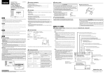
MS SERIES
MS 401 | MS 601 | MS 801
MS 401W | MS 601W | MS 801W
All-Weather Loudspeaker System
User Manual
MS 401 | MS 601 | MS 801
MS 401W | MS 601W | MS 801W
User Manual
MS 401 | MS 601 | MS 801
MS 401W | MS 601W | MS 801W
User Manual
Safety Precautions
Safety
P.03
Installation
P.04
Mounting the Speakers
P.05
Connection
P.06
Operating Tips
P.07
Troubleshooting
P.08
Specifications
P.09
Flying and installation of this
speaker cabinet must be carried
out by suitably qualified personnel
following the locally authorised
and approved safety standards.
Installation that allows direct
precipitation is not advised and
installation practise must prevent
liquids from entering the box.
Do not attempt to clean the
plastic enclosure with solvents or
petrochemical based cleaners.
Do not stack the speaker cabinet
in a manner that could cause
injury should a cabinet become
dislodged.
Do not place sources of heat
on the speaker cabinet such as
lighting equipment or smoke
machines, and where possible
please keep out of direct sunlight.
Attention
Register Your Product
Before connecting or operating your new
Quest Engineering speaker, please study the
accompanying instruction manual paying
particular attention to the operating precautions
and wiring procedure.
Thank you for choosing Quest. Please take
the time to complete your procuct registration
card which is included with the packaging.
Registering your Quest Engineering product will:
SAFETY
CONTENTS
Contents
3
• CONFIRM YOUR WARRANTY
Quest Engineering will not assume responsibility
for incorrect installation or operation of this
product.
• REGISTER YOUR PRODUCT
• PROTECT YOUR NEW PRODUCT
User Manual
MS Series
All-Weather Loudspeaker System
MS Series
All-Weather Loudspeaker System
User Manual
MS 401 | MS 601 | MS 801
MS 401W | MS 601W | MS 801W
User Manual
MS 401 | MS 601 | MS 801
MS 401W | MS 601W | MS 801W
User Manual
4
The MS Series all-weather loudspeakers are
the ideal choice for supplying high fidelity
sound in outdoor or marine applications. Their
advanced polymer housing is designed to be
acoustically inert and capable of surviving in
harsh environments.
The MS Series will stand up to moderate
amounts of moisture, however, they should not
be mounted where they will be directly exposed
to heavy rain or water splash. In colder climates,
bringing your loudspeakers inside for the winter,
when they are not being used, is advised.
Mounting hardware and grills are aluminium, to
drastically reduce corrosion. The vented cabinet
design and high-compliance woofers generate
realistic bass response in open air applications
and the high-efficiency soft dome tweeters yield
extended high-frequency response.
Note: The vent openings on the front baffle of
the loudspeakers should always be pointed
down, or away from any potential source of
water or other liquid, in order to avoid having
moisture enter the cabinet. Failure to observe
this precaution could lead to premature failure
of the loudspeaker.
Installation
Installing the MS Series, All-Weather
Loudspeaker System is not difficult. However,
correct wiring and proper placement play
a vital role in optimising sound quality. This
manual provides information on the placement,
connection and operation of your loudspeakers.
Please read it thoroughly and save it for future
reference.
Speaker Placement
Where speakers are placed significantly affects
their sound. Some general placement guidelines
are as follows. However, since all situations are
different, you should experiment with various
locations to determine where they ultimately
sound best.
Outdoor Use
Although the MS Series loudspeakers are ‘allweather’, when using them outdoors you will
extend their life and improve reliability if you
avoid mounting them where they will be exposed
to direct sunlight for extended periods of time.
User Manual
Mounting the Speakers
MS Series
All-Weather Loudspeaker System
Boundaries
In general, the MS Series loudspeakers will
produce the smoothest response and best stereo
image when located at least two feet from any
mounting environment boundaries, such as the
ground or floor, ceilings or walls. Moving the
speaker closer to one or more boundaries will
increase the bass output. In some installations,
the extra bass will enhance the sound which
may be desirable depending on the application.
“Hard” surfaces near a speaker can affect the
distribution of high frequency sound in the
listening area, as a result, the accuracy of the
stereo image may be impacted. If the speakers
are near the corners, point the speakers toward
the centre of the listening area. Experimenting
with speaker placement before final mounting is
the most important thing you can do to achieve
the best possible sound.
Before mounting the speakers in brackets, plan
the mounting location and method very carefully.
Follow the speaker placement guidelines, as
described on the preceding page of this manual,
and decide on the mounting locations. If you
plan to hide the speaker wires behind the
mounting surface, route the wires before you
mount the brackets. See the following section for
information on wiring.
The suggested method for attaching the
brackets to the mounting surface depends
on the structure and material of the mounting
surface. There are two typical situations. One is
with the brackets attached to a conventional wall
constructed with masonry material or dry wall
over wood studs. The other situation is with the
brackets mounted to a wood structure or some
other solid material.
When the speakers are mounted on masonry
walls or dry wall, use plastic screw anchors to
strengthen the attachment to the wall. When the
speakers are mounted to a solid panel the screw
anchors will not be required.
(a) Set the bracket in the desired installation
location. Be sure it is straight.
(b) Using the bracket as a template, mark the
location of the two mounting screw holes. Set
the bracket aside.
(c) If plastic anchors will be used, drill the
appropriate holes for them. If only self-tapping
screws are used, drill pilot holes with an 1/8" bit.
(d) Push the plastic screw anchors, if they are
being used, into the holes drilled for them. Drive
the mounting screws through the bracket, into
the holes, until they are firmly set.
(e) Connect the wire to the speaker, observing
the correct polarity (refer to next section). Set the
speaker in the mounting bracket and secure it by
inserting the provided threaded knob, tightening
it once the speaker is rotated to point in the
desired direction.
INSTALLATION
INSTALLATION
Description
5
Speaker Placement
Stereo imaging is generally best when a
speaker’s long axis is vertical, but horizontal
placement is by no means ruled out. Try the
speakers both ways to determine if the difference
in sound is important to you.
MS Series
All-Weather Loudspeaker System
User Manual
Making the Connections
Speaker Protection
Please use two-conductor stranded-type,
insulated wire to connect to the amplifier. “Lamp”
wire or “Zip Cord” are suitable. If running wiring
within the walls, make sure it complies with your
local building codes pertaining to low-voltage
wiring. Use at least 19 gauge for runs of less
than 50 feet. Use 14 gauge or larger wire for
longer runs. The resistance of 18 gauge or
smaller wire can cause a bass response peak if
used for more than a few feet.
Connect the positive conductor of one wire to
the red input connector of one speaker and
to the red, or “+” speaker output connector
of the associated amplifier channel. Connect
the negative conductor of the wire to the black
terminal of the speaker to the black, or “-”
connector of the associated amplifier channel.
Repeat the procedure for the other channel.
Be sure to follow exactly the same connection
procedure for both channels.
The MS Series speakers have a solid-state,
fully automatic tweeter protector. This reduces
the power to the tweeter when the speaker is
operated at unsafe power levels. The protector
resets itself when power is reduced to a safe
operating level. If high power operation causes
the tweeter to stop playing, please turn down the
volume control until normal sound resumes.
Preparing the Wire
Input Selector Switch
2Ω
W
0Ω
8 ohm
W
W
10
3
W 20W
49
16
3Ω 2 4 5Ω
0Ω
2
DIRECT
Note: The tweeter protector provides a
significant level of protection, however, it is no
guarantee that a tweeter cannot be damaged.
Please take care when operating the speakers at
a high volume level.
Maintenance
The MS Series drivers require no routine
maintenance. Do not let anything touch the
drivers. Do not vacuum clean the drivers or front
panels of the speakers. Some dust accumulation
on the drivers is normal and does not affect
the sound in any way. Heavy dirt buildup may
be carefully removed with a soft paintbrush,
if required. The enclosure of your MS Series
speakers require no maintenance, other than
regular dusting. Dust the speakers with a dry, or
slightly damp cloth. To clean the grills, remove
them from the speaker and vacuum them. Do not
vacuum the grille while they are on the speakers.
7
Protect Your Hearing
100 V
LINE
DIRECT
8 ohm
W
20
4
W 30W
24
12
2Ω 1 6 3Ω
5Ω
1Ω
W
0
MS Series
All-Weather Loudspeaker System
100 V
LINE
0
User Manual
5
W
0
5Ω 2 W 1 5 W 1 9
4
24
5Ω 3 6 5Ω
9
The MS Series speakers have colour-coded
push-to-connect input terminals that accept
virtually all types of speaker wire. Push the back
of the terminal to open the wire access hole. Put
the stripped wire, or pin terminal, into the hole
and release the terminal.
8 ohm
60
Speaker Input Connectors
9
1
The polarity – the positive/negative orientation of
the connections– for every speaker-to-wire and
wire-to-amplifier connection must be the same,
so the speakers will be “in phase”. If the polarity
of one connection is reversed, bass output is
reduced and stereo imaging is degraded. All
wire is marked as to identify the two conductors.
There may be ribs or a stripe on the insulation of
on conductor. The wire may have clear insulation
with different colour conductors (copper and
silver). Decide which conductor you will use for
“positive” and which for “negative”. Then be
consistent with every speaker-to-wire and wireto-amplifier connection.
DIRECT
40
Polarity
100 V
LINE
1
Estimate the amount of wire needed. Allowing
enough extra wire to move the speakers if
necessary. Separate the conductors of each wire
pair a few inches in from the end. Strip about
3/8" insulation from each conductor - careful not
to cut into the wire itself. Twist the strands of the
conductor together to avoid fraying. For outdoor
use, Quest recommend terminating the wire with
gold-plated pin-type terminals and insulating the
wire-to-pin connection with silicone filled heatshrink tubing. Bare copper wire can corrode and
cause unreliable connection over time.
OPERATING TIPS
Wire
2
6
MS 401 | MS 601 | MS 801
MS 401W | MS 601W | MS 801W
User Manual
0
CONNECTION
MS 401 | MS 601 | MS 801
MS 401W | MS 601W | MS 801W
User Manual
All speakers, including the Quest MS Series, with
extended periods of use can damage hearing
beyond repair. Quest Engineering suggest care
when using any sound equipment over long
periods.
ATTENTION: Make sure the input slector switch
has been set to the correct location. For normal,
low impedence operation ensure the input
selector switch is set to 8Ω.
For line voltage settings, ensure that the
number of speaker units, multiplied by the
power setting, does not exceed the amplifier
power. Doing so will result in extreme damage
to amplifiers.
MS Series
All-Weather Loudspeaker System
User Manual
8
Most difficulties with high fidelity equipment result
from loose or poor connections, bad connecting
cables, or switches in the wrong positions.
No Sound
Ensure the Input Selector Switch is set to the
correct position. It is rare for a speaker to fail
completely. When there is no sound, check all the
speaker wire connections and the setting of the
amplifier’s tape monitor or speaker selector switch.
Dull or Muted Sound
Operating the speakers at unsafe power level
activates the automatic tweeter protector. Turn
down the amplifier volume control and the protector
will automatically restore signal to the tweeter. Also
check the amplifier’s tone controls or “high filter”
switch.
Distorted Sound
Distortion at moderate levels can be caused by
loose connections, or stray wire strands shorting
out adjacent wires at the amplifier or speaker
terminals. If you hear distortion, or any other type of
buzzing or rattling sound from an individual driver,
contact your Quest Engineering dealer. Distortion at
high levels is the result of either reaching the power
limit of the amplifier or of the speaker. Turn down
the volume to prevent damage.
Noise or Hum
Continuous background noise or hum are always
from the electronic equipment and not from the
speakers.
General Troubleshooting Tips
Buzzes and Noise in the Sound System: Getting
rid of unwanted noises is a study in itself. Most of
the noise, (apart from undesir-able program) will fall
into three categories.
(A) White noise. This is the hiss that suggests that
the gain structure is set incorrectly. Something in
the signal chain is boosting too much or an input
is set too sensitive. If your equipment has gain
User Manual
MS Series
All-Weather Loudspeaker System
MS 401 | MS 601 | MS 801
MS 401W | MS 601W | MS 801W
User Manual
switches on it, set them all the same. If the switch
is labelled +4dB, set them all to that figure. If one
piece of equipment seems to be overloading, set
them all to -10/-20dB and be prepared to boost
the input level. The last unit in the chain should be
set to +4 dB at the output stage if possible when
connected to the line level input.
Quest Engineering MS Series Specifications
MS 401 / 401W
Specifications
Peak Power
100W
Power Handling
50W
(B) Low frequency hum. This is often caused by
noise from the power leads being picked up by
the audio signal cables. The preferred solution is
to connect up your system with “balanced” XLR
microphone cables. Especially if you are running the
cables a long distance, (more than 5Mtrs /15 Ft).
The other solution is to make sure that your audio
cables are as far from power cables as possible.
Type
Bass Reflex
Impedance Nominal
8Ω
Transformer Tappings
25W / 20W / 15W / 10W + 8Ω Direct
(C) Buzz. Sometimes you can experience a hum
and buzz together. A buzz is almost always a
problem with the “earthing” of the system. It will
often occur when you have the system powered
from sperate power outlets in the same building
or audio and lighting sharing a common power
circuit. Even when the audio and lighting systems
are powered from separate sources, there can still
be a common earth between them. For example,
a smoke machine may be powered from the
lighting system, yet the trigger mechanism could
be connected to the audio system through the
audio multi-core/snake. An earth connection
between the audio and lighting will now exist and
a buzz could be amplified in the audio system. The
simple solution is to power your audio circuit and
everything con-nected to it from the same source.
If the buzz persists, check your signal cables, one
may have an earth/shield disconnected.
A cheap but possibly life saving investment is a
domestic power tester to check that the power
supply sockets are correctly wired. Faulty or
incorrectly wired power is a booby trap more
common than you think.
Components
LF
4" Poly Propelyne Cone, Rubber Surround, 25 mm Voice Coil
HF
Dome Tweeter PEI Diaphragm, 20 mm Voice Coil
Angle of coverage
90˚ x 90˚
Sensitivity 1W @ 1 meter
88 dB
Max SPL
108 dB
Frequency Response
80Hz-20Khz ±4dB
Crossover Frequency
3000Hz
Crossover
12 dB
Enclosure Material
UV Stabilised ABS
Bracket Material
Aluminium
Grill Material
Aluminium
Dimensions
153 mm x 180.5 mm x 278 mm
Weight
2.6 kg
Shipping Dimensions
203 mm x 226 mm x 319 mm
Shipping Weight
3.3 kg
SPECIFICATIONS
TROUBLESHOOTING
MS 401 | MS 601 | MS 801
MS 401W | MS 601W | MS 801W
User Manual
9
All specifications are correct at time of printing, Quest Engineering reserves the right to change
specifications at any time and won’t be held responsible for any typographic errors in this publication.
It is wise to avoid switching on or off devices
in the signal path while the speaker system is
powered and turned up. Otherwise loud clicks
and bangs could result. When shutting down the
system, always turn the speakers off first. This is
to prevent the speaker amplifying the sound of the
other equipment in the chain being shut down.
The reverse is true when powering up. Mixers
and effects on first, power amplifiers or powered
speakers on last.
MS Series
All-Weather Loudspeaker System
User Manual
10
Quest Engineering MS Series Specifications
Quest Engineering MS Series Specifications
MS 601 / 601W
Specifications
MS 801 / 801W
Specifications
Peak Power
160W
Peak Power
240W
Power Handling
80W
Power Handling
120W
Type
Bass Reflex
Type
Bass Reflex
Impedance Nominal
8Ω
Impedance Nominal
8Ω
Transformer Tappings
40W / 30W / 20W / 10W + 8Ω Direct
Transformer Tappings
60W / 40W / 30W / 20W + 8Ω Direct
Components
Components
LF
6.5" Poly Propelyne Cone, Rubber Surround, 35 mm Voice Coil
LF
8" Mica and PP Cone, Rubber Surround, 35 mm Voice Coil
HF
Dome Tweeter, Silk Membrane, 25mm Voice Coil
HF
Dome Tweeter, Silk Membrane, 25mm Voice Coil
Angle of coverage
90˚ x 90˚
Angle of coverage
90˚ x 90˚
Sensitivity 1W @ 1 meter
90 dB
Sensitivity 1W @ 1 meter
91 dB
Max SPL
110 dB
Max SPL
114 dB
Frequency Response
60Hz-20Khz ±3 dB
Frequency Response
55Hz-20Khz ±4 dB
Crossover Frequency
3000Hz
Crossover Frequency
3000Hz
Crossover
12 dB
Crossover
12 dB
Enclosure Material
UV Stabilised ABS
Enclosure Material
UV Stabilised ABS
Bracket Material
Aluminium
Bracket Material
Aluminium
Grill Material
Aluminium
Grill Material
Aluminium
Dimensions
195 mm x 214 mm x 335 mm
Dimensions
259 mm x 290 mm x 445 mm
Weight
4.35 kg
Weight
5.75 kg
Shipping Dimensions
247 mm x 287 mm x 377 mm
Shipping Dimensions
320 mm x 360 mm x 487 mm
Shipping Weight
5.5 kg
Shipping Weight
7 kg
All specifications are correct at time of printing, Quest Engineering reserves the right to change
specifications at any time and won’t be held responsible for any typographic errors in this publication.
User Manual
MS 401 | MS 601 | MS 801
MS 401W | MS 601W | MS 801W
User Manual
MS Series
All-Weather Loudspeaker System
SPECIFICATIONS
SPECIFICATIONS
MS 401 | MS 601 | MS 801
MS 401W | MS 601W | MS 801W
User Manual
11
All specifications are correct at time of printing, Quest Engineering reserves the right to change
specifications at any time and won’t be held responsible for any typographic errors in this publication.
MS Series
All-Weather Loudspeaker System
User Manual
www.questaudio.net