1
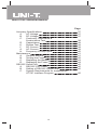
Model UT70C: OPERATING MANUAL
Table of Contents
Title
Overview
Unpacking Inspection
Safety Information
Rules For Safe Operation
International Electrical Symbols
The Meter Structure
Rotary Switch
Functional Buttons
Display Symbols
Measurement Ranges
A.
Selecting a Measurement Range
B.
Manual Ranging and Autoranging
Measurement Operation
A.
AC Voltage Measurement
B.
DC Voltage Measurement
C.
DC Milivolt Measurement
D.
Measuring Continuity, Resistance,
Conductance & Capacitance
E.
Testing Diodes
F.
DC or AC Current Measurement
G.
Frequency & Duty Cycle Measurement
MAX MIN Recording Mode
PEAK MAX MIN Mode
Operation of Hold Mode
Operation of Auto Hold Mode
The Use of Relative Value and Relative
Percentage Value Mode
Turning on the Display Backlight
Analogue Bar Graph Display
Full Icons Display
Sleep Mode
General Specifications
1
Page
3
4
5
6
8
8
9
10
12
14
14
14
16
16
17
18
19
23
24
26
28
30
31
32
33
34
34
35
35
36
Model UT70C: OPERATING MANUAL
Accuracy Specifications
A.
AC Voltage
B.
DC Voltage
C.
Continuity, Resistance &
Conductance Test
D.
Capacitance
Diodes Test
E.
F.
DC Current
G.
AC Current
H.
Frequency & Duty Cycle
Maintenance
A.
General Service
B.
Testing the Fuses
C.
Replacing the Battery
D.
Replacing the Fuses
RS232C Serial Port
A.
RS232C Port Cable
B.
Setting of RS232C Serial Ports
C.
System Requirements for Installing the
UT70C Interface Program
2
Page
37
37
37
38
38
38
39
39
40
41
41
42
43
44
45
45
45
46
Model UT70C: OPERATING MANUAL
Overview
This Operating Manual covers information on safety and
cautions. Please read the relevant information carefully
and observe all the Warnings and Notes strictly.
Warning
To avoid electric shock or personal injury, read the
"Safety Information" and "Rules for Safe Operation"
carefully before using the Meter.
Your multimeter is an intelligent digital one, a precise
instrument with a resolution of 8,000 counts and up-todate automatic computer calibrating function. High
resolution A/D converter and micro-controller data
processing technique is adopted in the Meter, featured
with intelligence, high precision and multi-functions. The
Meter can be widely used in laboratory, field service,
domestic and other applications. All the functions and
ranges have overloaded protection.
3
Model UT70C: OPERATING MANUAL
Unpacking Inspection
Open the package case and take out the Meter. Check
the following items carefully to see any missing or
damaged part:
Item
1
2
3
4
5
6
7
8
Description
Operating Manual
Test Lead
Test Clip
9V Battery (NEDA1604, 6F22 or 006P)
(installed)
RS232C Interface Cable
CD-ROM (Installation Guide & Computer
Interface Software)
Holster
Tilt Stand
Qty
1 piece
1 pair
1 pair
1 piece
1 piece
1 piece
1 piece
1 piece
In the event you find any missing or damage, please
contact your dealer immediately.
4
Model UT70C: OPERATING MANUAL
Safety Information
CE Version: The Meter complies with the standards
IEC61010-1:in pollution degree 2, overvoltage category
CAT III 1000V, CAT IV 600V and double insulation .
UL Version: The Meter complies with the standards UL61010B-1,
in pollution degree 2, overvoltage category CAT II 1000V
and double insulation.
CAT. II: Local level, appliance, PORTABLE EQUIPMENT
etc., with smaller transient voltage overvoltages than
CAT. III
CAT. III: Distribution level, fixed installation, with smaller
transient overvoltages than CAT. IV
CAT IV: Primary supply level, overhead lines,
cablesystems etc.
Use the Meter only as specified in this operating manual,
otherwise the protection provided by the Meter may be
impaired.
In this manual, a Warning identifies conditions and
actions that pose hazards to the user, or may damage
the Meter or the equipment under test.
A Note identifies the information that user should pay
attention on.
International electrical symbols used on the Meter and
in this Operating Manual are explained on page 8.
5
Model UT70C: OPERATING MANUAL
Rules For Safe Operation (1)
Warning
To avoid possible electric shock or personal injury,
and to avoid possible damage to the Meter or to the
equipment under test, adhere to the following rules:
l
l
l
l
l
l
l
l
Before using the Meter inspect the case. Do
not use the Meter if it is damaged or the case
(or part of the case) is removed. Look for cracks
or missing plastic. Pay attention to the insulation
around the connectors.
Inspect the test leads for damaged insulation
or exposed metal. Check the test leads for
continuity. Replace damaged test leads with
identical model number or electrical
specifications before using the Meter.
Do not apply more than the rated voltage, as
marked on the Meter, between the terminals or
between any terminal and grounding.
The rotary switch should be placed in the right
position and no any changeover of range shall
be made during measurement is conducted to
prevent damage of the Meter.
Never working at an effective voltage over 60V
in DC or 30V rms in AC for there is danger of
electric shock.
Use the proper terminals, function, and range
for your measurements.
Do not use or store the Meter in an environment
of high temperature, humidity, explosive,
inflammable and strong magnetic field. The
performance of the Meter may deteriorate after
dampened.
When using the test leads, keep your fingers
behind the finger guards.
6
Model UT70C: OPERATING MANUAL
Rules For Safe Operation (2)
l Disconnect circuit power and discharge all highvoltage capacitors before testing resistance,
conductance, continuity, diodes, current, or
capacitance.
l Before measuring current, check the Meter's
fuses and turn off power to the circuit before
connecting the Meter to the circuit.
l Replace the battery as soon as the battery
indicator
appears. With a low battery, the
Meter might produce false readings that can
lead to electric shock and personal injury.
l Remove test leads, RS232C interface cable and
test clip from the Meter and turn the Meter power
off before opening the Meter case.
l When servicing the Meter, use only the same
model number or identical electrical
specifications replacement parts.
l The internal circuit of the Meter shall not be
altered at will to avoid damage of the Meter and
any accident.
l Soft cloth and mild detergent should be used
to clean the surface of the Meter when servicing.
No abrasive and solvent should be used to
prevent the surface of the Meter from corrosion,
damage and accident.
l The Meter is suitable for indoor use.
l Turn off the Meter when it is not in use and
take out the battery when not using for a long
time.
l Constantly check the battery as it may leak when
it has been using for some time, replace the
battery as soon as leaking appears. A leaking
battery will damage the Meter.
7
Model UT70C: OPERATING MANUAL
International Electrical Symbols
AC (Alternating Current)
DC (Direct Current)
AC or DC
Grounding
Double Insulated
Deficiency of Built-In Battery
Continuity Test
Diode
Capacitance Test
Fuse
Warning. Refer to the Operating Manual
Conforms to Standards of European Union
The Meter Structure (see figure 1)
1
2
3
4
5
(figure 1)
8
Front Case
LCD Display
Functional Buttons
Rotary Switch
Input Terminals
Model UT70C: OPERATING MANUAL
Rotary Switch
Below table indicated for information about the rotary
switch positions.
Rotary
Switch
Position
OFF
V
V
mV
A
mA
Function
Power is turned off.
AC voltage measurement.
DC voltage measurement.
DC millivolt measurement.
: Continuity test.
: Resistance measurement.
: Capacitance test.
Diode Test.
AC or DC Current Measurement
from 0.001A to 10.00A .
AC or DC Current Measurement
from 0.1mA to 800.0mA.
9
Model UT70C: OPERATING MANUAL
Functional Buttons (1)
Below table indicated for information about the functional
button operations.
Button Measuring
Operation Performed
Function
Continuity
Turn the continuity buzzer on and
Test
off in resistance measurement
mode.
At OFF
Press while turning on the
position
Meter to disable the beeper at all
functions except short circuit and
diode testing.
At REC
To toggle between 100ms
mode or
response time and 1ms response
REC mode time under REC mode except at
plus Hold
resistance, capacitance and
mode
continuity range.
MAX Any rotary
Starts recording of maximum and
MIN switch
minimum values. Steps the
position
display through the sequence of
except at
present, high (MAX), low (MIN)
conductance and average (AVG) readings at
mode.
any mode.
In 1ms response time, it steps
through only MAX and MIN
reading.
At OFF
To select 1 second high accuracy
position
response time, press and hold
down MAX MIN while turning the
rotary switch to any function
setting.
RANGE Any rotary
1. Press RANGE to enter the
switch
manual ranging mode; the
position
Meter beeps.
2. Press RANGE to step
through the ranges available
for the selected function; the
Meter beeps.
3. Press and hold RANGE for
over 1 second to return to
autoranging; the Meter
beeps.
10
Model UT70C: OPERATING MANUAL
Functional Buttons (2)
HOLD Any rotary
switch
position
Conductance
mode
A , mA
REL
Hz
At OFF
position
Any rotary
switch
position
Press HOLD to enter and exit the
Hold mode in any mode; the
Meter beeps.
Press HOLD to toggle between
conductance and resistance
value. Present resistance value
is kept.
Press
to select capacitance
test.
Press
to select DC or AC
current. DC is default.
To disable the Sleep Mode, press
while turning on the Meter.
Press REL to enter and exit the
and % mode in any measuring
mode; the Meter beeps.
V , V , 1.
mV , A ,
mA
2.
Display
Backlight
Press Hz to enter frequency
measurement mode; the
Meter beeps.
Press Hz again to enter duty
cycle measurement mode;
the Meter beeps.
3. Press Hz again to return to
the last measurement mode;
the Meter beeps.
Press once to turn the Display
Backlight on and it shall shut off
automatically in around 60
seconds later.
11
Model UT70C: OPERATING MANUAL
Display Symbols (1) (see figure 2)
(figure 2)
No. Symbol
3
Meaning
The Meter is in the auto range mode in
which the Meter automatically selects the
range with the best resolution.
The battery is low.
Warning: To avoid false readings,
which could lead to possible electric
shock or personal injury, replace the
battery as soon as the battery indicator
appears.
Indicates negative reading.
4
Test of diode.
1
2
5
6
7
8
9
10
11
The continuity buzzer is on.
The relative value mode is on, which
display the present value minus the stored
value.
The relative percentage value mode is
% on. It displays the percentage value of
the relative value and stored value.
DATA Data hold is active.
HOLD
DC AC Indicator for DC/AC voltage or current.
The displayed value is the mean value.
8000mV Display the present chosen range.
%
Percent, used for duty cycle
measurements.
12
Model UT70C: OPERATING MANUAL
Display Symbols (2)
12
13
14
15
16
17
W::
,
kW:
K :
k , M MW:
M :
Ohm. The unit of resistance.
kilohm. 1 x 10³ or 1000 ohms.
Megohm. 1 x 10⁶ or 1,000,000
ohms.
Hz, kHz, Hz:
Hertz. The unit of frequency.
MHz kHz:
Kilohertz. 1 x 10³ or 1000 hertz.
MHz:
Meghertz. 1 x 10⁶ or1,000,000
hertz.
V, mV V:
Volts. The unit of voltage.
mV:
Millivolt. 1 x 10⁻³ or 0.001 volts.
A, mA A:
Amperes (amps). The unit of
current.
mA:
Milliamp. 1 x 10⁻³ or 0.001
amperes.
F, F, nF F:
Farad. The unit of capacitance.
mF:
Microfarad. 1 x 10⁻⁶ or 0.000001
farads.
nF:
Nanofarad. 1 x 10⁻⁹ or
0.000000001 farads.
nS
S:
Siemens. The unit of
conductance.
nS:
Nanosiemens. 1 x 10⁻⁹ or
0.000000001 siemens.
Maximum, minimum and average
recording mode enabled. Present reading
displayed.
100ms 100ms response time.
MAX Maximum reading displayed.
MIN Minimum reading displayed.
AVG Average reading displayed.
Analogue Provides an analogue indication of the
Bar present input, quick response.
Graph
Polarity indicator for the analogue bar
graph display, no display for positive.
The input value is too large for the selected
range.
RS232C Computer and the Meter is connected
properly. Data output is in progress.
13
Model UT70C: OPERATING MANUAL
Measurement Ranges (1)
A measurement range determines the highest value the
Meter can measure. Most Meter functions have more
than one range. See "Accuracy Specifications."
A. Selecting a Measurement Range
Being in the right measurement range is important:
l If the range is too low for the input, the Meter displays
to indicate an overload.
l If the range is too high, the Meter will not display
the most accurate measurement.
B. Manual Ranging and Autoranging
The Meter has both manual range and autorange options:
l
l
In the autorange mode, the Meter selects the best
range for the input detected.
This allows you to switch test points without having
to reset the range.
In the manual range mode, you select the range.
This allows you to override autorange and lock the
Meter in a specific range.
The Meter defaults to the autorange mode in
measurement functions that have more than one range.
When the Meter is in the autorange mode,
is
displayed.
To enter and exit the manual range mode:
14
Model UT70C: OPERATING MANUAL
Measurement Ranges (2)
1.
Press RANGE.
The Meter enters the manual range mode and
turns off.
Each presses of RANGE increments the range.
When the highest range is reached, the Meter
wraps to the lowest range.
2.
To exit the manual range mode, press and hold
RANGE for over one second.
The Meter returns to the autorange mode and
is displayed.
Note
l In Hold and MAX MIN mode, press RANGE exits
these measurement modes and enters manual
range mode.
l In Hz measurement mode, press RANGE to attenuate
10 times of input signal amplitude which can increase
the Meter sensitivity and stabilize the correct reading.
15
Model UT70C: OPERATING MANUAL
Measurement Operation (1)
A. AC Voltage Measurement (see figure 3)
red
black
(figure 3)
Warning
To avoid harms to you or damages to the Meter from
electric shock, please do not attempt to measure
voltages higher than 1000V / 750V rms although
readings may be obtained.
The AC Voltage ranges are: 800.0mV, 8.000V, 80.00V,
800.0V and 1000V. To measure AC Voltage, connect
the Meter as follows:
1.
2.
3.
Insert the red test lead into the V Hz terminal
and the black test lead into the COM terminal.
Set the rotary switch to V .
Connect the test leads across with the object being
measured.
The measured value shows on the display, which
is effective value of sine wave (mean value
response).
Note
l In each range, the Meter has an input impedance
of 10M
. This loading effect can cause
measurement errors in high impedance circuits. If
the circuit impedance is less than or equal to 10k ,
the error is negligible (0.1% or less).
l When AC voltage measurement has been completed,
disconnect the connection between the testing leads
and the circuit under test.
16
Model UT70C: OPERATING MANUAL
Measurement Operation (2)
B. DC Voltage Measurement (see figure 4)
red
black
(figure 4)
Warning
To avoid harms to you or damages to the Meter from
electric shock, please do not attempt to measure
voltages higher than 1000V / 750V rms although
readings may be obtained.
The DC Voltage ranges are: 8.000V, 80.00V, 800.0V and
1000V. To measure DC Voltage, connect the Meter as
follows:
1.
2.
3.
Insert the red test lead into the V Hz terminal
and the black test lead into the COM terminal.
Set the rotary switch to V
.
Connect the test leads across with the object being
measured.
The measured value shows on the display.
Note
l In each range, the Meter has an input impedance
of 10M
. This loading effect can cause
measurement errors in high impedance circuits. If
the circuit impedance is less than or equal to 10k ,
the error is negligible (0.1% or less).
l When DC voltage measurement has been completed,
disconnect the connection between the testing leads
and the circuit under test.
17
Model UT70C: OPERATING MANUAL
Measurement Operation (3)
C.
DC Millivolt Measurement (see figure 5)
red
black
(figure 5)
Warning
To avoid harms to you or damages to the Meter from
electric shock, please do not attempt to measure
voltages higher than 1000V / 750V rms although
readings may be obtained.
The DC Millivolt ranges are: 80.00mV and 800.0mV.
These ranges have more than 4000M . To measure
DC Millivolt, connect the Meter as follows:
1.
2.
3.
Insert the red test lead into the V Hz terminal
and the black test lead into the COM terminal.
Set the rotary switch to mV
.
Connect the test leads across with the object being
measured.
The measured value shows on the display.
Note
l In each range, the Meter has an input impedance
of 10M . This loading effect can cause
measurement errors in high impedance circuits. If
the circuit impedance is less than or equal to 10k ,
the error is negligible (0.1% or less).
l When DC millivolt measurement has been completed,
disconnect the connection between the testing leads
and the circuit under test.
18
Model UT70C: OPERATING MANUAL
Measurement Operation (4)
D.
Measuring Continuity, Resistance,
Conductance & Capacitance
Warning
To avoid damages to the Meter or to the devices
under test, disconnect circuit power and discharge
all the high-voltage capacitors before measuring
continuity, resistance, conductance and capacitance.
When measuring capacitance, use the DC Voltage
function to confirm that the capacitor is discharged.
Never attempt to input over 60V in DC or 30V rms in
AC to avoid personal dangerous.
Testing for Continuity (see figure 6)
Select
Test
red
black
(figure 6)
To test for continuity, connect the Meter as below:
1. Insert the red test lead into the V Hz terminal
and the black test lead into the COM terminal.
2. Set the rotary switch to
and press
to
select
measurement mode.
3. The buzzer sounds if the resistance of a circuit under
test is less than 100 .
Note
l The LCD displays
indicating the circuit being
tested is open.
l When continuity testing has been completed,
disconnect the connection between the testing leads
and the circuit under test.
19
Model UT70C: OPERATING MANUAL
Measurement Operation (5)
Resistance Measurement (see figure 7)
Select
W Test
red
black
(figure 7)
The resistance ranges are: 800.0 , 8.000k , 80.00k ,
800.0k , 8.000M
and 80.00M
. To measure
resistance, connect the Meter as follows:
1.
2.
3.
Insert the red test lead into the V Hz terminal
and the black test lead into the COM terminal.
Set the rotary switch to
, resistance
measurement is default or press
to select
measurement mode.
Connect the test leads across with the object being
measured.
The measured value shows on the display.
Note
l The test leads can add 0.1 to 0.2 of error to
resistance measurement. To obtain precision
readings in low-resistance measurement, that is the
range of 800.0 , short-circuit the input terminals
beforehand, using the relative value function button
REL to automatically subtract the value measured
when the testing leads are short-circuited from the
reading.
l For high-resistance measurement (>1M ), it is normal
taking several seconds to obtain a stable reading.
20
Model UT70C: OPERATING MANUAL
Measurement Operation (6)
l
The LCD displays
indicating open-circuit for the
tested resistor or the resistor value is higher than
the maximum range of the Meter.
l When resistance measurement has been completed,
disconnect the connection between the testing leads
and the circuit under test.
Conductance Measurement (see figure 8)
Select
nS Test
red
black
(figure 8)
The resistance ranges from 0.01nS to 80nS. To measure
conductance, connect the Meter as follows:
1.
2.
3.
Insert the red test lead into the V Hz terminal
and the black test lead into the COM terminal.
Set the rotary switch to
and press RANGE
to select nS measurement mode.
Connect the test leads across with the object being
measured.
The measured value shows on the display.
Note
l It is possible to press HOLD to toggle between
conductance and resistance value during the
measurement of conductance.
l When conductance measurement has been completed,
disconnect the connection between the testing leads
and the circuit under test.
21
Model UT70C: OPERATING MANUAL
Measurement Operation (7)
Capacitance Measurement (see figure 9)
Select
nF Test
red
black
(figure 9)
The Meter's capacitance ranges are: 1.000nF, 10.00nF,
100.0nF, 1.000 F, 10.00 F and 100.0 F. To measure
capacitance, connect the Meter as follows:
1.
2.
3.
Insert the red test lead or the red test clip into the
V Hz terminal and the black test lead or black
test clip into the COM terminal.
Set the rotary switch to
and press
to
select nF measurement mode.
Connect the test leads or the test clips across with
the object being measured.
The measured value shows on the display.
Note
l For testing the capacitor with polarity, connect the
red test clip or red test lead to anode & black test
clip or black test lead to cathode instead.
l It takes a longer time when testing a high capacitor
value, the testing time is around 15 seconds in
100 F range.
l When capacitance measurement has been completed,
disconnect the connection between the testing leads
and the circuit under test.
22
Model UT70C: OPERATING MANUAL
Measurement Operation (8)
E.
Testing Diodes (see figure 10)
red
black
(figure 10)
Warning
To avoid possible damage to the Meter and to the
device under test, disconnect circuit power and
discharge all high-voltage capacitors before testing
diodes.
Use the diode test to check diodes, transistors, and other
semiconductor devices. The diode test sends a current
through the semiconductor junction, then measures the
voltage drop across the junction. A good silicon junction
drops between 0.5V and 0.8V.
To test a diode out of a circuit, connect the Meter as
follows:
1.
2.
3.
Insert the red test lead into the V Hz terminal
and the black test lead into the COM terminal.
Set the rotary switch to
.
For forward voltage drop readings on any
semiconductor component, place the red test lead
on the component's anode and place the black test
lead on the component's cathode.
The measured value shows on the display.
23
Model UT70C: OPERATING MANUAL
Measurement Operation (9)
Note
l In a circuit, a good diode should still produce a
forward voltage drop reading of 0.5V to 0.8V;
however, the reverse voltage drop reading can vary
depending on the resistance of other pathways
between the probe tips.
l Connect the test leads to the proper terminals as
said above to avoid error display.
l The LCD will display
indicating open-circuit for
wrong connection.
l The unit of diode is Volt (V), displaying the positiveconnection voltage-drop value.
l When diode testing has been completed, disconnect
the connection between the testing leads and the
circuit under test.
F.
DC or AC Current Measurement (see figure 11)
Select AC
or DC Test
A or
mA
black
red
(figure 11)
Warning
Never attempt an in-circuit current measurement
where the open-circuit voltage between the circuit
and ground is greater than 250V.
If the fuse burns out during measurement, the Meter
may be damaged or the operator himself may be
hurt. Use proper terminals, function, and range for
the measurement. When the testing leads are
connected to the current terminals, do not parallel
them across any circuit.
24
Model UT70C: OPERATING MANUAL
Measurement Operation (10)
The current measurement has 2 measurement positions
on the rotary switch: A and mA .
The A has a 8.000A and 10.00A range, with auto ranging;
the mA has a 80.00mA and 800.0mA range, with auto
ranging.
To measure current, do the following:
1. Turn off power to the circuit. Discharge all highvoltage capacitors.
2. Insert the red test lead into the A or mA or terminal
and the black test lead into the COM terminal.
3. Set the rotary switch to A or mA .
Use the A terminal and A measurement position
if the current value to be tested is an unknown.
4. The Meter defaults to DC current measurement
mode. To toggle between DC and AC current
measurement function, press
.
AC current is displayed as an mean value (calibrated
against sine wave effective value).
5. Break the current path to be tested. Connect the
red test lead to the more positive side of the break
and the black test lead to the more negative side of
the break.
6. Turn on power to the circuit.
The measured value shows on the display.
Note
l For safety sake, the measuring time for high current,
that is 8.000A and 10.00A range, should be 10
seconds for each measurement and the interval
time between 2 measurements should be greater
than 15 minutes.
l When current measurement has been completed,
disconnect the connection between the testing leads
and the circuit under test.
25
Model UT70C: OPERATING MANUAL
Measurement Operation (11)
G. Frequency & Duty Cycle Measurement (see figure 12)
Select Hz
or Duty Cycle
Test
red
black
(figure 12)
Frequency Measurement
The measurement ranges are: 1kHz, 10kHz, 100kHz
and 1MHz. The maximum measurement range is 1MHz.
To measure frequency, connect the Meter as follows:
1.
2.
3.
4.
Insert the red test lead into the V Hz terminal
and the black test lead into the COM terminal.
Set the rotary switch to any voltage or current
measurement positions.
Press Hz to display the frequency of present signal.
Connect the test leads across with the object being
measured.
The measured value shows on the display.
Note
l It is recommended to use mV
range which has
the highest sensitivity.
l The attenuate amplitude of signal is different from
different measuring positions and ranges, therefore
the required input amplitude is different when
measuring frequency at different measuring positions
and ranges.
l When Hz measurement has been completed,
disconnect the connection between the testing leads
and the circuit under test.
26
Model UT70C: OPERATING MANUAL
Measurement Operation (12)
Duty Cycle Measurement
The duty cycle measurement range is 0.01% ~ 99.99%.
To measure duty cycle:
1. Set up the Meter to measure frequency.
2. To select duty cycle, press Hz again (or until the %
symbol is shown on the display).
3. Connect the test leads across with the object being
measured.
The measured value shows on the display.
Note
l It is recommended to use mV
range.
l The polarity of trigger slope is positive.
l The attenuate amplitude of signal is different from
different measuring positions and ranges, therefore
the required input amplitude is different when
measuring duty cycle at different measuring positions
and ranges.
l When duty cycle measurement has been completed,
disconnect the connection between the testing leads
and the circuit under test.
27
Model UT70C: OPERATING MANUAL
MAX MIN Recording Mode (1) (see figure 13)
Select MAX,
MIN, AVG or
Present value
red
black
(figure 13)
MAX MIN recording mode applies to all measurement
functions except at conductance measurement function.
MAX MIN recording mode captures and stores the
maximum and minimum input value detected, and
calculates a running average of all readings taken.
In the MAX MIN mode, when the Meter detects an input
that is below the recorded minimum or above the recorded
maximum, the Meter beeps and records the new minimum
(MIN) or maximum (MAX) value.
In the MAX MIN mode, you can also display a running
average of all readings taken since the MAX MIN mode
was activated. Displaying the average reading allows
you to "smooth" a rapidly changing input by displaying
a stable reading on the digital display.
The MAX MIN mode has a pre-set response time of
100ms. A shorter response time captures shorter events,
but with decreased accuracy. If you want 1 second
response time, that can be selected after power on the
Meter.
To use the MAX MIN mode as follows:
28
Model UT70C: OPERATING MANUAL
MAX MIN Recording Mode (2)
MAX MIN
Function
To enter the
MAX MIN
mode.
1.
To exit the
MAX MIN
mode.
Press MAX MIN for over 1 second.
The Meter exists MAX MIN. Recorded
values are erased and the Meter stays
in the selected range.
Action
Make sure that the Meter is in the
desired measurement function and
range.
2. Press MAX MIN to enter MAX MIN
recording mode. The present
reading is displayed, and the Meter
is locked in the present range, and
REC is displayed.
3. Each time a new low or high value
is recorded, the Meter beeps and
displays a new reading.
(In MAX MIN mode, Sleep Mode
function will be disabled.)
To view the
Press MAX MIN to step through on the
MAX, MIN,
sequence of present readings, high
AVG or present (MAX), low (MIN) and average (AVG)
reading.
readings.
To stop and
l Press HOLD to stop recording, the
resume
recorded values will not erase.
recording
l Press HOLD again to resume
without erasing
recording.
stored values
To select
l The pre-set response time is 100ms.
response time l Press
to select 1 ms response
time in REC mode. It is called
under PEAK MAX MIN mode. (In
1 ms response time, it steps
through on the sequence of MAX
and MIN readings only.)
l With the rotary switch in the OFF
position, press and hold down MAX
MIN while turning on the rotary
switch to select 1 second high
accuracy response time. (MAX MIN
readings for the frequency counter
are recorded only in the 1 second,
high accuracy response mode.)
29
Model UT70C: OPERATING MANUAL
PEAK MAX MIN Mode (see figure 14)
Select MAX
or MIN
Select 1ms
response time
red
black
(figure 14)
PEAK MAX MIN mode is an additional function of .
Pressing
to toggle between 100ms response time
and 1ms response time. This function can only be enabled
when the Meter is under REC mode or REC mode plus
Hold mode except at
mode.
To enter PEAK MAX MIN mode:
l Press MAX MIN or MAX MIN and HOLD to enter
REC mode.
l Then press
to enter PEAK MAX MIN mode (1ms
response time), it steps through the sequence of
MAX and MIN reading ONLY.
30
Model UT70C: OPERATING MANUAL
Operation of Hold Mode
Warning
To avoid possibility of electric shock, do not use
Hold mode to determine if circuits are without power.
The Hold mode will not capture unstable or noisy
readings.
The Hold mode is applicable to all measurement functions.
With the Auto Hold function, it automatically holds the
present reading on the display, freeing you to concentrate
on the placement of the test leads when working in
dangerous or difficult situations.
l
l
l
l
l
l
l
Press HOLD to enter Hold mode; the Meter beeps.
Press HOLD again or RANGE or turn the rotary
switch to exit Hold mode; the Meter beeps.
In Hold mode, DATA HOLD is displayed on the
LCD.
In conductance measurement mode, press HOLD
to toggle between resistance and conductance value.
Present resistance value is kept.
The Meter displays
when the selected range is
overloaded.
The Meter beeps when a positive result is obtained
from continuity test, whether it is under the Hold
mode or not.
If you are in MAX MIN recording mode or mode
when HOLD is selected, Hold interrupts the function.
The display does not update, but recorded readings
are not erased. Press HOLD again to resume
recording.
31
Model UT70C: OPERATING MANUAL
Operation of Auto Hold Mode
Auto Hold means you no need to press HOLD, the
readings on the LCD will be hold automatically.
Conditions to enter Auto Hold Mode:
l When input signal is larger than AC/DC 100mV,
Auto Hold mode will be enabled automatically.
l When the change of signal three times continuously
within 3 digits, it will hold the last value; the Meter
beeps.
l Considers every value as the base value. When
the Meter detects an input which is above the base
value 300 digits, the Meter beeps, and holds and
displays the value as the new base value.
32
Model UT70C: OPERATING MANUAL
The Use of Relative Value and Relative
Percentage Value Mode
The and % mode applies to all measurement functions,
with auto ranging.
REL mode can be used together with Auto Hold and
MAX MIN mode.
The definition is as follows:
l Relative value ( ) = present value - stored value
For instance, if the stored value is 20.0V and the
present value is 22.0V, the reading would be 2.0V.
If a new measurement value is equal to the stored
value then display 0.0V.
l Relative percentage value ( %) =
(relative value
stored value) X 100%
To enter or exit and % mode:
l Use rotary switch to select the desired measurement
function before selecting REL . If measurement
functions change manually after REL is selected,
the Meter exits the REL mode.
l Press REL to enter
mode, and the present
measurement range is locked and display the last
measurement value as "0" as the stored value.
Then if carrying out measurement at this time, the
LCD will display the value as the result.
l Press REL again to enter % mode, and the
present measurement range is locked and display
the last measurement value as "0" as the stored
value. Then if carrying out measurement at this
time, the LCD will display the % value as the result.
l Press REL again or turn the rotary switch to reset
the stored value and exit % and mode, returning
to normal measurement mode.
33
Model UT70C: OPERATING MANUAL
Turning on the Display Backlight
Warning
In order to avoid the hazard arising from mistaken
readings in insufficient light or poor vision, please
use the Display Backlight function.
l
l
Press to turn on the Display Backlight and it will
automatically off after about 60 seconds.
Press and hold for about 2 seconds to turn the
Display Backlight off.
Analogue Bar Graph Display
The analogue bar graph likes the needle in a traditional
analogue meter (AMM). It refreshes 50 times a sec,
which is 10 times faster than that of digital display and
is applied to zero adjustment and observation of rapidly
changing signal that make digital display hard to read.
The analogue display is divided uniformly into 10 scales
and composed of 41 segments; of which the full-range
value corresponds to the full-range value of the
measurement range that has been selected. The polarity
of the measured value is displayed as "-" on the left of
the analogue display: positive polarity is not displayed.
For example, when 80V range is selected, the full-range
value of the analogue display is 80V, and as the full
range is uniformly divided into 10 grades, each grade
denotes 8V; If the input is 40V, the high-lighted bar-shape
will be at the position indicated by the number 5. if the
input is -40V, a "-" sign will appear on the left of the
analogue display.
There is no analogue displaying value when making
measurement of frequency, diode, conductance and
capacitance.
34
Model UT70C: OPERATING MANUAL
Full Icons Display
If the Meter is turned on with any functional button being
pressed on, the LCD will display all the icons and maintain
this mode until the button is released 3 seconds later.
Sleep Mode
l
To preserve battery life, the Meter automatically
turns off if you do not turn the rotary switch or press
any button for about 30 minutes. The buzzer beeps
three times 5 minutes before turning off.
l The Meter can be activated by turning the rotary
switch or pressing any button.
If the Meter is activated by turning the rotary switch,
it will start from the switch selected function.
l To disable the Sleep Mode, press
while turning
on the Meter.
l In MAX MIN mode, the Sleep Mode is disabled.
35
Model UT70C: OPERATING MANUAL
General Specifications
l Maximum Voltage between :1000V rms.
any Terminals and
Grounding
:1A,250V fast type glass
l
fuse, 5x20mm.
l
l
:10A,250V fast type glass
fuse, 5x20mm.
:8000, updates 5 times
/second.
o
o
:Operating:5 C~40 C
l Temperature
o
o
(41 F ~104 F).
o
o
Storage:-10 C~50 C
o
o
(14 F~122 F).
o
o
:<80% @ 5 C - 31 C;
l Relative Humidity
o
o
<50% @ 31 C - 40 C.
:Operating: 2000 m.
l Altitude
Storage:
10000 m.
:One piece of 9V
l Battery Type
NEDA1604 or 6F22 or
006P.
:Display .
l Battery Deficiency
:Display DATA HOLD.
l Data Holding
:Display
.
l Negative reading
:Display .
l Overloading
l Equipped with full icons display.
l Auto and manual range selectable.
l Dimensions (HxWxL) :195 x 90 x 39 mm.
:Approximate 550g (battery
l Weight
included).
l Safety/Compliances : CE Version: IEC61010 CAT III
1000V, CAT IV 600V overvoltage
and double insulation standard.
UL Version:UL 61010B-1,
CAT II 1000V overvoltage
double insulation standard.
l Certification:
/UL
This meter is suitable for indoor use.
Maximum Display
36
Model UT70C: OPERATING MANUAL
Accuracy Specifications (1)
Accuracy: (a% reading + b digits), guarantee for 1 year.
o
o
Operating temperature: 23 C 5 C.
Relative humidity: <80%.
o
Temperature coefficient: 0.1 x (specified accuracy) / 1 C
A.
AC Voltage
Range Resolution
Accuracy
50Hz~60Hz
40Hz~400Hz
(1.5%+4)
800mV
100 V
8V
1mV
(1%+3)
(1.5%+3)
80V
10mV
800V
100mV
(2.5%+4)
1000V
1V
Overload Protection:
AC/DC: 1000V rms
Remarks:
l Input impedance: 10M .
l Displays effective value of sine wave (mean value
response).
l Frequency response 40Hz ~ 400Hz.
B. DC Voltage
Range Resolution Accuracy Overload Protection
10 V
(0.1%+3)
80mV
100 V
800mV
1mV
8V
AC/DC: 1000V rms
10mV
(0.1%+1)
80V
100mV
800V
1V
1000V
Remarks:
l At 80mV ~ 800mV Range:
Input impedance 4000M .
l At 8V ~ 1000V Range:
Input impedance 10M .
37
Model UT70C: OPERATING MANUAL
Accuracy Specifications (2)
C.
Continuity, Resistance & Conductance Test
Overload
Range
Resolution Accuracy Protection
Continuity Test
0.1
Approximate
(800.0 )
100
800
0.1
(0.5%+3)
8k
1
80k
10
(0.5%+1)
500V rms
800k
100
8M
1k
80M
10k
(2%+3)
Conductance Test 0.01nS
(2%+10)
(80nS)
Remarks:
l Continuity Test (800.0 ):
Buzzer beeps continuously.
Open circuit voltage approximate 0.7V.
l At 800 ~ 80M Range:
Open circuit voltage approximate 0.7V.
l Conductance Test (80ns):
80nS = 12.5M .
D.
Capacitance
Range
Resolution
Accuracy
1nF
1pF
(3%+5)
10nF
10pF
100nF
100pF
(2%+3)
1 F
1nF
10nF
10 F
(3%+5)
100nF
100 F
Remark:
Reading under 1nF is only for reference.
E.
Overload
Protection
500V rms
Diodes Test
Range
Resolution
Overload Protection
Diode
1mV
500V rms
Remarks:
l Open circuit voltage approximate 3V.
l Displays approximate forward voltage drop reading.
38
Model UT70C: OPERATING MANUAL
Accuracy Specifications (3)
F.
DC Current
Range Resolution Accuracy
80mA
10 A
800mA
100 A
8A
1mA
10A
10mA
Overload
Protection
1A,250V fast type
glass fuse, 5x20mm.
(0.3%+2)
10A,250V fast type
glass fuse, 5x20mm.
Remark:
l At 8A & 10A Range:
For continuous measurement 10 seconds and
interval time between 2 measurements greater than
15 minutes.
G. AC Current
Range Resolution Accuracy
80mA
10 A
800mA
100 A
8A
1mA
10A
10mA
Overload
Protection
1A,250V fast type
(0.8%+2) glass fuse, 5x20mm.
(1.2%+2) 10A,250V fast type
glass fuse, 5x20mm.
Remarks:
l At 8A & 10A Range:
For continuous measurement 10 seconds and
interval time between 2 measurements greater than
15 minutes.
l Displays effective value of sine wave (mean value
response).
l Frequency response 40Hz ~ 1kHz.
39
Model UT70C: OPERATING MANUAL
Accuracy Specifications (4)
H.
Frequency & Duty Cycle
Frequency - At mV
Range
Range
Resolution
Accuracy
1kHz
0.01Hz
10kHz
0.1Hz
(0.02%+1)
100kHz
1Hz
1MHz
10Hz
Remarks:
l Input sensitivity as follows:
<100kHz: 100mV rms;
100kHz: 500mV rms;
l Maximum input amplitude: 30V rms.
Frequency - At V
&V
Overload
Protection
500V rms
Range
Range
Accuracy
Overload Protection
10Hz~100kHz (0.1%+3)
1000V
Remarks:
l Input amplitude: 500mV rms.
l Maximum input amplitude: 30V rms.
Frequency - At A
& mA
Range
Accuracy
50Hz ~ 10kHz
(0.1%+3)
Range
Overload Protection
1A,250V fast type
glass fuse, 5x20mm.
10A,250V fast type
glass fuse, 5x20mm.
Remark:
l Input amplitude: 3000 digits.
Duty Cycle
Range
Resolution
Accuracy
1% ~ 99%
0.01%
(1%+5)
40
Overload
Protection
500V rms
Model UT70C: OPERATING MANUAL
Accuracy Specifications (5)
Remarks:
l Reading is only for reference purpose.
l At mV
8V Range:
Positive pulse width 30 s.
Maintenance (1)
This section provides basic maintenance information
including battery and fuse replacement instruction.
Warning
Do not attempt to repair or service your Meter unless
you are qualified to do so and have the relevant
calibration, performance test, and service information.
To avoid electrical shock or damage to the Meter, do
not get water inside the case.
A.
General Service
l
Periodically wipe the case with a damp cloth and
mild detergent. Do not use abrasives or solvents.
To clean the terminals with cotton bar with detergent,
as dirt or moisture in the terminals can affect readings.
Turn the Meter to OFF position when it is not in use
and take out the battery when not using for a long
time.
Do not store the Meter in a place of humidity, high
temperature, explosive, inflammable and strong
magnetic field.
l
l
l
41
Model UT70C: OPERATING MANUAL
Maintenance (2)
B.
Testing the Fuses
Warning
To avoid electrical shock or personal injury, remove
the test leads and any input signals before replacing
the battery or fuse.
To prevent damage or injury, install ONLY replacement
fuses with identical amperage, voltage, and speed
ratings.
To test the fuse:
1.
2.
Set the rotary switch to
and select
by
pressing .
Plug a test lead into the terminal V Hz and touch
the probe tip to the 10A or mA terminal.
l If the Meter beeps, the fuse is good.
l If the display shows , replace the fuse and test
again.
l If the display shows any other value, have the
Meter serviced and contact your dealer
immediately.
If the Meter does not work while the fuse is all right, send
it to your dealer for repair.
42
Model UT70C: OPERATING MANUAL
Maintenance (3)
C.
Replacing the Battery (see figure 15)
Holster
The Meter
(figure 15)
Warning
To avoid false readings, which could lead to possible
electric shock or personal injury, replace the battery
as soon as the battery indicator " " appears.
To replace the battery:
1.
2.
3.
4.
5.
6.
Turn the Meter to OFF position and remove all
connections from the terminals.
Take out the Meter from the holster.
Remove the 3 rubber feet and then 3 screws from
the case bottom, and separate the case top from
the case bottom.
Remove the battery from the battery connector.
Replace the battery with a new 9V battery
(NEDA1604, 6F22 or 006P).
Rejoin the case bottom and case top, and reinstall
the 3 screws and 3 rubber feet.
43
Model UT70C: OPERATING MANUAL
Maintenance (4)
D.
Replacing the Fuses (see figure 15)
Warning
To avoid electrical shock or arc blast, or personal
injury or damage to the Meter, use specified fuses
ONLY in accordance with the following procedure.
To replace the Meter's fuse:
1.
2.
3.
4.
5.
6.
7.
8.
Turn the Meter to OFF position and remove all
connections from the terminals.
Take out the Meter from the holster.
Remove the 3 rubber feet and 3 screws from the
case bottom, and separate the case top from the
case bottom.
Remove the 4 screws fixing the PCB on the input
terminals, gently take apart the PCB and reverse it.
Remove the fuse by gently prying one end loose,
then take out the fuse from its bracket.
Install ONLY replacement fuses with the identical
type and specification as follows and make sure the
fuse is fixed firmly in the bracket.
Fuse 1: 1A,250V fast type glass fuse, 5x20mm.
Fuse2: 10A,250V fast type glass fuse, 5x20mm.
Rejoin the PCB and the case top, and reinstall the
4 screws.
Rejoin the case bottom and case top, and reinstall
the 3 screws and 3 rubber feet.
Replacement of the fuses is seldom required. Burning
of a fuse always results from improper operation.
44
Model UT70C: OPERATING MANUAL
RS232C Serial Port (1)
A.
RS232C Port Cable
The
Computer
Meter
D-sub
D-sub
D-sub
9 Pin 25 Pin Pin
Remark
9 Pin Male
FemaleFemale Name
2
3
4
5
6
7
8
B.
2
3
4
5
6
7
8
RX
Receiving Data
TX Transmitting Data
DTR Data Terminal Ready
GND
Grounding
DSR Data Set Ready
RTS Request to Send
CTS
Clear to Send
3
2
20
7
6
4
5
Setting of RS232C Serial Ports
Default of RS232C serial port for communication is set
as:
Baud Rate 9600
Start bit
1 (always 0)
Stop bit
1 (always 1)
Data bits 8
Parity Odd None
45
Model UT70C: OPERATING MANUAL
RS232C Serial Port (2)
C. System Requirements for Installing the UT70C
Interface Program
To use UT70C Interface Program, you need the following
hardware and software:
l An IBM PC or equivalent computer with 80586 or
higher processor and 640 x 480 pixel or better
monitor.
l Microsoft Windows 95 or above.
l At least 16 MB of RAM.
l At least 8MB free space in hard drive.
l Can access to a local or a network CD-ROM.
l A free serial port.
l A mouse or other pointing device supported by
Windows.
Please refer to the included CD-ROM "Installation Guide
& Computer Interface Software" for installing and
operating instructions of the UT70C Interface Program.
~ END ~
This operating manual is subject to change without notice.
46
Model UT70C: OPERATING MANUAL
47
Model UT70C: OPERATING MANUAL
Copyright 2001 Uni-Trend International Limited.
All rights reserved.
Manufacturer: UNI-TREND TECHNOLOGY(DONG GUAN)LIMITED
Address: Dong Fang Da Dao, Bei Shan Dong Fang Industrial
Development District, Hu Men Town, Dong Guan City,
Guang Dong Province, China
Headquarters: Uni-Trend International Limited
Address: Rm901, 9/F, Nanyang Plaza 57 Hung To Road
Kwun Tong Kowloon, Hong Kong
Tel: (852) 2950 9168
Fax: (852) 2950 9303
Email: [email protected]
http://www.uni-trend.com
48