1
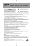
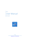
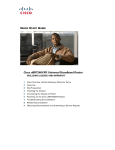
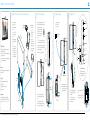
Installing Cisco TelePresence MX300 - Wall Mount
Cut the straps and lift off
the outer covering.
ii
Remove the upper foam
protection.
Touch controller
with cable
• Wall bracket, LCD video unit bracket, bottom adapter and
back cover. Screwdriver.
• LCD video unit, touch controller, microphones and cables.
Screws, screwdriver and gloves.
• Two microphones
Outer
covering
i
• Presentation cable
(VGA to DVI-I;
stereo audio)
• Ethernet cable
• Four screws (two for
fastening the bottom
adapter; two spares)
This box contains two
smaller boxes: One with
the Touch controller, and
one accessories box with
the microphones, cables,
screws and screwdriver.
• Hexagonal screwdriver
• Two pairs of gloves
i
Note: Always use the provided gloves when handling
the LCD video unit to avoid stains on the unit’s surface.
• Power cable
iii Lift out the rectangular
box behind the LCD video
unit.
The MX300 with a wall mount bracket is delivered in two
boxes with the following parts:
Accessories box:
Lift the LCD video unit carefully
out of the bottom tray and place
it gently face down on a steady,
soft surface. Two people working
together are required for this
operation.
4
Connecting the cables
3
3
Mounting the bottom adapter
Local area
network (LAN)
Remove the cable channel
lid to get access to the
holes for the screws.
Touch controller
Cable channel lid
(for strain relief)
31 kg / 68 lb
PC video input
LCD video unit
CAUTION: Take care not to subject the camera for
any stress (turn it parallel to the LCD video unit).
ii
PC audio input
Unscrew and remove the four pre-mounted screws
at the back of the LCD video unit (see illustration)
(tool: hexagonal screwdriver).
8,622
i
Note: Leave the LCD
video unit in the bottom
tray for now.
The MX300 delivery
2
Mounting the LCD video unit bracket
Audio line output
(cable not included)
Power
switch
You will reuse these screws in the next step.
79,4
1
Unpacking the MX300 box with the LCD video unit, Touch controller and accessories
Microphones
Power
supply
AC Input
AC Input
For maintenance only
Reset factory settings
1,64
Manpower
45,7
LCD video unit connectors
Two people working together are required to mount the LCD
video unit to the wall.
Note: You will not have access to the
connectors after you have fastened the
LCD video unit to the wall.
Bottom adapter
Dimensions
Height (not including the camera): 840 mm / 33 in.
LCD video
unit
Width: 1290 mm / 51 in.
ii
Depth (including brackets): 190 mm / 7.5 in.
LCD video
unit bracket
Weight: 38 kg / 84 lb
Documentation
The user documentation for this product, including
compliance and safety information, is available on the Cisco
web site, http://www.cisco.com/go/telepresence/docs.
78-20503-01 MX300 Wall Mount Installation Sheet | 2011 NOVEMBER | © 2011 Cisco Systems, Inc. All rights reserved.
Bottom tray
iii Move the LCD video unit bracket toward the
LCD video unit and align the four holes for the
screws.
Fasten the bracket to the LCD video unit
with the four screws that you removed in the
previous step (tool: hexagonal screwdriver).
Slide the bottom adapter into the
LCD video unit and fasten it with two
of the screws in the accessories box
(tool: hexagonal screwdriver).
i
Thread the cables up through the hole
in the bracket and connect them to the
LCD video unit.
The connectors are placed at the
rear side of the LCD video unit. See
illustration for details.
ii
Snap on the cable channel lid for strain
relief.
Note: When you position the cables side
by side it is easier to snap on the lid.
Snap on the back cover to
hide the connectors and
cables.
ii
iii When the LCD video unit is in place, tighten
the two setting screws (tool: the long hexagonal
screwdriver).
Fasten the wall bracket to the wall according
to the safety instructions above. You need
four screws with anchors suiting your type of
wall (screws and anchors are not provided).
The upper setting screw is to lock
the unit to the bracket.
In regular meeting rooms the recommended
distance between the floor and the lower
edge of the bracket is 0.77 m / 30.2 in.
The power switch is located above the power connector
on the rear side of the LCD video unit. You can reach it
through the hole in the back cover on the rear side of the
LCD video unit.
The illustrations to the right show in general where to place your
MX300 system depending on the window positions in the room.
For each room layout the MX300 position(s) marked with A are
preferred, then B and finally C. You should avoid any position
not shown in the illustrations.
8
You can access
the power switch
through this hole
in the back cover.
Finishing up
A
Microphone placement
Correctly placed microphones are very important to obtain a
good conferencing experience.
i
Remove the protective foil from the LCD video unit.
ii
If required, clean the Touch display (not the LCD video display) using the dry cleaning cloth provided.
iii Unfold the rear-mounted foot on the Touch controller to increase its tilt.
Lower
setting
screw
B
B
i
• Good illumination of a person’s face to avoid annoying
shadows.
• No direct light on the LCD video display to avoid reflections.
When the home menu and contact list appear on the
Touch controller the system is ready to use.
A
You should aim for:
Switch on the system.
iii Wait while the MX300 starts up. Normally this takes just a
few minutes. If an automatic software upgrade occurs the
start-up process may take up to 15 minutes.
Upper
setting
screw
CAUTION: To alter the camera position always use the
Camera Control panel on the Touch controller; never move
the camera manually when the power is switched on.
A
According to the relevant international safety standard for IT products the
wall is required to support four times the actual load, which implies that
the MX300 system must be mounted to a wall which supports at least:
4 × 38 kg = 152 kg / 335 lb.
Make sure the cables are lead
out at the bottom.
SAFETY REQUIREMENT: The equipment shall be installed
close to the socket outlet. The socket outlet shall be easily
accessible after installation.
34 kg / 75 lb
38 kg / 84 lb
(including brackets)
Plug in the cables from the LCD video unit as appropriate.
A
It is highly recommended that this wall mount unit
is installed by trained personnel, considering local
building regulations.
i
The placement of the video system in a room will influence the
overall conferencing experience both at the local and remote
sites.
C
WARNING: Due to the size and mass of this product,
it is very important that the wall mount unit is safely
installed according to these installation instructions
and that the wall is able to safely support the product.
Carefully lift the LCD video unit and slide the LCD
video unit bracket onto the wall bracket. Two
people working together are required for this
operation.
LCD video unit placement
B
ii
You can lock/unlock
the back cover by
lifting this handle. Use
both hands if required.
i
7
Switching on the system
A
6
Mounting the LCD video unit to the wall
C
5
Snapping on the back cover
B
Installing Cisco TelePresence MX300 - Wall Mount
We recommend that you place the microphone(s) as close to
all users as possible, and that you avoid putting equipment
with noisy fans, such as computers and projectors, close to a
microphone.
If you are using more than one microphone, place them far
apart to minimize the interference. The required distance
between the microphones depends on the acoustics of your
room; normally 2 m (6.5 ft) will suffice.
EMC A-Class declaration
声 明
此为A级产品,在生活环境中,该产品可能会造成无线电干扰。在这种
情况下,可能需要用户对其干扰采取切实可行的措施。
Wall bracket
The lower setting screw is to fix the
unit parallel to the wall.
78-20503-01 MX300 Wall Mount Installation Sheet | 2011 NOVEMBER | © 2011 Cisco Systems, Inc. All rights reserved.
WARNING:
Thisis is
a class
A product.
In a domestic
environment
WARNING: This
a class
A product.
In a domestic
environment
this
product
may
cause
radio
interference
in
which
case
the
user
may
this product may cause radio interference in which case thebeuser
required to take adequate measures.
may be required to take adequate measures.
On our web site you will find an overview of the
worldwide Cisco contacts.
Go to: http://www.cisco.com/web/siteassets/contacts.
Corporate Headquarters
Cisco Systems, Inc.
170 West Tasman Dr.
San Jose, CA 95134 USA
The MX300 internal microphone may suffice in a small office
or meeting room when all participants are closer to the display
than 2.5 m (8 ft). Still a correctly placed external microphone
often performs better. The internal microphone is automatically
disabled when connecting an external microphone.
If you want to learn more about optimizing your office
or meeting room for video conferencing, please read
the Video conferencing room primer and Guidelines
for video conferencing room acoustics documents
that are available on the Cisco web site,
http://www.cisco.com/go/telepresence/docs.