1
QUICK START GUIDE
Cisco RF Gateway 10
1
Overview
2
Site Preparation
3
Chassis Installation
4
Connecting Cables
5
Powering on the Cisco RF Gateway 10
6
Configuring the Cisco RF Gateway 10 at Startup
7
Troubleshooting
8
Obtaining Documentation and Submitting a Service Request
9
Related Documents
1 Overview
The Cisco RF Gateway 10 (RFGW-10) is a Carrier Class Universal Edge Quadrature Amplitude Modulation (UEQAM) platform
that offers concurrent support for Standard and High Definition Digital Broadcast Television, Switched Digital Video (SDV),
Video on Demand (VoD), and DOCSIS/Modular CMTS services.
The Cisco RFGW-10 UEQAM is a chassis based product that is based on open standards with superior performance, capacity,
power consumption, ease of management and scalability. All components of the Cisco RFGW-10 UEQAM are designed for high
availability including dual Supervisor and Ethernet switching line cards, 1:N Universal Edge QAM line cards, dual Timing and
Control line cards, dual load balancing and load sharing DC PEM and integrated RF switching modules.
The Cisco RFGW-10 is targeted to the Cable Operators worldwide, and is optimized for operators requiring carrier class high
availability solutions and wanting to collapse video and data over cable EQAM systems into common platform. A collapsed
Universal EQAM architecture achieves the following business benefits; EQAM resource utilization gains, cost efficiencies, rack
space optimization, reduced cost and complexity of management, and high availability for all services. The Cisco RFGW-10 is
part of the Cisco’s Cable ecosystem, and is fully integrated and tested as part of the Cisco Digital Broadband Delivery System
(DBDS) video solution and Cisco uBR10012 DOCSIS 3.0 and Modular CMTS solution.
The Cisco RFGW-10 is a centralized switching architecture leveraged from the Cisco® Catalyst® 4500 Series switches. The
Cisco RFGW-10 is a 13RU Carrier class, modular chassis designed for providing front to back airflow and system level
redundancy. All chassis components are hot-swappable and redundant. The chassis supports “wire-once” cabling for RF line
cards and an integrated dual-zone RF switch matrix. The supervisor engine provides non-blocking, robust Layer 2-4 switching
with the addition of wire-speed 10-Gigabit Ethernet uplinks, 136Gbps capacity and 102mpps packet throughput.
The Cisco RFGW-10 system is a UEQAM that supports both upstream and downstream RF cards over a frequency range of
5MHz – 1.2GHz. The initial line card release is a UEQAM downstream card that supports the DOCSIS (1.0/2.0/3.0), the
EURODOCIS, and J-DOCSIS specifications. Additionally, the card supports High Definition Digital Broadcast Television,
Switched Digital Video (SDV), Video on Demand (VoD) video delivery.
Based on the Cisco IOS networking software, the Cisco RFGW-10 supports advanced switching and routing features. The
platform supports full upgradeability, ensuring investment protection as software enhancements and industry standards
continue to evolve.
Warning
Only trained and qualified personnel should be allowed to install, replace, or service
this equipment. Statement 1030
Cisco RF Gateway 10 Components
The front-side components include the supervisor cards, RF line cards, and the front panel LCD. The rear-side components
include the fan assembly, RF Switch cards (coaxial terminations), Timing, Communication, and Control (TCC) (DOCSIS Timing
Interface (DTI) Clock) cards, and the DC PEM modules.
All components (excluding the LCD) are hot-swappable and field replaceable. A fully configured system will operate with a
single DC PEM installed; the second PEM is required for power supply redundancy and power load sharing.
Note
Proper configuration of the DC PEM requires that both the external power connections, Input 1 and Input 2, are
connected to the external power source and the GND connections are connected to the Earth GND. Input 1 and Input
2 on the DC are not redundant power inputs. If only one of the inputs is connected to the external power, the Cisco
RFGW-10 UEQAM will not power on correctly.
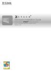
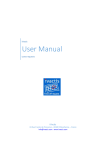
Figure 1 shows the location of the front-side and the rear-side system components for the Cisco RFGW-10 UEQAM.
2
Figure 1
Cisco RF Gateway 10 chassis components - Front and Rear View
3
4
2
271377
1
7
5
6
1
Universal RF line card slots
2
Supervisor card slots
3
LCD/Pushbutton panel
4
Fan assembly
5
TCC / DTI card slots
6
DC PEM modules
7
RF Switch Cards/Coaxial cable termination slots
3
2 Site Preparation
Do not unpack the chassis until you are ready to install it. Keep the chassis in the shipping container to prevent accidental
damage until you determine an installation site.
Before you install the Cisco RFGW-10, review the following:
• The environmental conditions your installation site must meet to maintain normal operation.
• The power requirements that must be in place at your installation site.
• The cabling requirements for your installation site.
• Rack-mounting requirements.
• The equipment required to install the Cisco RFGW-10 UEQAM.
For more details on site preparation, refer to “Preparing Your Site for Installation” chapter in the Cisco RF Gateway 10
Hardware Installation Guide.
4
3 Chassis Installation
The Cisco RFGW-10 UEQAM is shipped with all ordered (configured) components installed in the chassis. A fully configured
Cisco RFGW-10 UEQAM (configured for redundancy support, including 10 RF line cards) weighs approximately 275 lbs. The
chassis alone weighs 91 lbs. The chassis with the fan tray, TCC cards, and all RF switch cards weighs 138 lbs. It is not
recommended that the Cisco RFGW-10 system be installed with all components in the system.
In a fully loaded chassis, the removable components (modules, line cards) weigh approximately 184 lbs. To enable two people
to install the system safely, we recommend that the following components be removed from the chassis before installing the
chassis in the rack:
• Fan assembly (13.0 lbs— optional, it is recommended to leave this installed)
• DC power supplies (15.5 lbs each)
• Supervisor cards (5.5 lbs each)
• TCC cards (2.0 lbs each)
• RF switch cards (2.5 lbs— optional, given the quantity and total weight contribution of these cards)
• RF line cards (9.5 lbs each)
Caution
You must use a hydraulic lift or forklift to move a fully populated chassis.
Installation Methods
Rack-mounting is the preferred method of installation for the Cisco RFGW-10 UEQAM. You can mount the chassis:
• Front mount or mid mount
• In a 19 inch wide (standard), four-post equipment rack or two-post, using the rack-mount brackets in the accessory kit
Note
The Cisco RFGW-10 UEQAM usually ships fully loaded. It is recommended that you remove the components from the
chassis to make the chassis lighter for your rack installation. It is recommended to remove the two DC PEMs, the two
Supervisor Cards, and the 10 Universal RF Line Cards.
General Rack Installation Guidelines
When planning your rack installation, consider the following guidelines:
• The Cisco RFGW-10 UEQAM requires a minimum of 13 rack units (22.75 inches or 577.85 mm) of vertical rack space.
Measure the proposed rack location before mounting the chassis in the rack.
• Before using a particular rack, check for obstructions (such as a power strip) that could impair rack-mount installation. If
a power strip does impair a rack-mount installation, remove the power strip before installing the chassis, and then replace
it after the chassis is installed.
• Allow sufficient clearance around the rack for maintenance. If the rack is mobile, you can push it back near a wall or cabinet
for normal operation and pull it out for maintenance (installing or moving cards, connecting cables, or replacing or
upgrading components). Otherwise, allow 36 inches (914.4 mm) of access to remove field replaceable units.
• Maintain a minimum clearance of 4 inches (101.6 mm) on the front and the rear of the chassis for the cooling air inlet and
exhaust ports, respectively. Avoid placing the chassis in an overly congested rack or directly next to another equipment rack;
otherwise, the heated exhaust air from the other equipment can enter the inlet air vents and cause a high temperature
condition inside the router.
Caution
To prevent chassis overheating, never install a Cisco RFGW-10 UEQAM in an enclosed room that is not properly
ventilated or air conditioned.
5
• Always install the heavier equipment in the lower half of the rack to maintain a low center of gravity to prevent the rack
from falling over.
• Install and use the cable-management brackets included with the Cisco RFGW-10 UEQAM to keep the cables organized
and out of the way of the cards and processors. Ensure that the cables from the other equipment already installed in the
rack do not impair access to the cards or require you to disconnect cables unnecessarily to perform equipment maintenance
or upgrades.
• Install rack stabilizers (if available) before you mount the chassis.
• Provide an adequate chassis ground (earth) connection for your Cisco RFGW-10 UEQAM chassis.
Table 1 shows the weight and dimensions of the Cisco RFGW-10 UEQAM.
Table 1
Physical Characteristics of Cisco RFGW-10 UEQAM
Characteristic
Description
Height
13RU (22.75 in / 577.85mm)
Width
17.48 in. (444mm) with rack-mounts
Depth
Overall depth including card handles, UCH2 cable holders,
power supply handles: 24.93 inches (633.2mm)
Depth from the front rack-mount bracket including card
handles, UCH2 cable holders, power supply handles: 24.13
inches (612.9mm)
Depth from the front rack-mount bracket including rear RF
cable management bracket 26 inches (660mm)
Weight of fully configured chassis
275 lbs (125 kg - with RFGW-DS48 line card and two DC
PEMs)
Rack-mounting a Cisco RFGW-10 UEQAM
The Cisco RFGW-10 UEQAM can be installed in either front mount or mid mount configuration. The chassis rack-mounting
flanges must be secured directly to the chassis before lifting it into the rack. For installing the Cisco RFGW-10 UEQAM
rack-mount brackets, go to:
• Chassis Front Rack-mount Brackets Installation, page 9
• Chassis Mid-Mounted Rack-Mount Bracket Installation, page 10
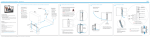
Verifying Rack Dimensions
Before you install the chassis, measure the space between the vertical mounting flanges (rails) on your equipment rack to verify
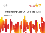
that the rack conforms to the measurements shown in Figure 2.
Step 1
Mark and measure the distance between the two holes on the left and right mounting rails. The distance should measure
18.31 inches ± 0.06 inches (46.5 cm ± 0.15 cm).
Note
Measure the pairs of holes near the bottom, middle and top of the equipment rack to ensure that the rack posts are
parallel.
Step 2
Measure the space between the inner edges of the left front and right front mounting flanges on the equipment rack.
The space must be at least 17.7 inches (45 cm) to accommodate the chassis, which is 17.25 inches (43.8 cm) wide and
fits between the mounting posts on the rack.
6
Figure 2
Verifying Equipment Rack Dimensions
Mounting flanges
Hole centerline
to hole centerline
18.31 inches ± 0.06 inches
(46.5 cm ± 0.15 cm)
28014
Minimum usable
aperture 17.7 inches
(45.0 cm)
Installing the Chassis Installation Brackets
Each chassis is shipped with two chassis installation brackets in the accessory kit. These brackets are to aid in installing a chassis
into a 19 inch rack and used as a support base to vertically position and set the chassis before the rack-mount screws are
installed.
To install the chassis installation brackets into a rack, complete the following steps:
Step 1
Determine where in the rack you want the chassis to be mounted. If you are mounting more than one chassis in the
rack, then start from the bottom up or the center of the rack. Install the chassis installation bracket where the chassis
bottom will be positioned vertically in the rack.
Step 2
Secure the chassis installation bracket to the front rails with the rack-mount screws.
Step 3
If there is a second internal rack rail, which is not more than 20 inches from the front rail, you can position the second
installation bracket to act as a rear support for the chassis during installation.
Figure 3 shows the brackets attached in a rack.
7
Chassis Installation Bracket
273445
Figure 3
Chassis
installation
bracket
Note
After the chassis is installed and secured to the rack, the chassis installation brackets can be removed from the rack.
The brackets are not needed for supporting the chassis when all the rack-mount screws are installed.
Installing the Chassis Installation Handles
This section explains how to attach the chassis installation handles to the chassis.
Before installing the chassis in the rack, it is recommended that you install a chassis lifting handle to each side of the chassis to
aid in lifting the chassis onto the rack.
Note
It is recommended to install the two side chassis installation handles while unpacking to aid in moving the chassis off
the palette.
Note
Chassis installation handles should not be installed if the chassis is to be mid mounted.
To install the chassis installation handles on a Cisco RFGW-10 UEQAM, complete the following steps:
Step 1
Locate the two M5 threaded holes on the upper center of each side of the chassis that align with the handle captive
screws.
Step 2
Install the two chassis installation handles on either side of the chassis and tighten the captive screws.
8
Ensure that the captive screws are secured tightly prior to loading the handles to prevent injury or damage to the
chassis.
Figure 4
Attaching the Chassis Installation Handles to the Cisco RFGW-10 UEQAM
273450
Caution
After the chassis rack-mount brackets are installed, additional handles can be installed onto the front of the rack-mount
brackets. The rack-mount brackets allow a low and high installation of the handles onto the bracket depending on the chassis
installation (low or high in the rack).
Attaching the Chassis Rack-mount Brackets
This section explains how to attach the front and the mid rack-mount brackets to the chassis. Before installing the chassis in the
rack, you must install the rack-mount brackets on each side of the chassis.
Note
The rear RF cable management bracket is installed on the chassis after you install the chassis rack-mount brackets and
mount the chassis in the rack.
Chassis Front Rack-mount Brackets Installation
To install the front rack-mount brackets on a Cisco RFGW-10 UEQAM, complete the following steps:
9
Step 1
Locate the threaded holes on the front sides of the chassis that align with the holes in the rack-mount bracket. Ensure
that you hold the front rack-mount bracket with the ear and holes facing outward and towards the front of the chassis
(see Figure 5).
Step 2
Install all six M5 undercut flat head screws (provided in the accessory kit) to secure each of the rack-mounting bracket
to the chassis. Three screws are installed on each end of the rack-mounting bracket.
Step 3
Repeat Step 1 through Step 2 on the other side of the chassis.
Step 4
Install the chassis in the rack. To install the Cisco RFGW-10 UEQAM in the rack, go to Installing the Cisco RFGW-10
UEQAM in a Rack, page 11.
Figure 5
Attaching the Front Rack-mount Brackets
3
1
273684
1
2
1
Front rack-mount bracket
2
Cisco RFGW-10 UEQAM Chassis
3
Front rack-mount bracket screws
Chassis Mid-Mounted Rack-Mount Bracket Installation
If you are rack-mounting the chassis using a mid-mounted configuration, then it provides for the chassis being recessed in the
rack or installed in a two-post rack.
Note
10
Chassis installation handles cannot be installed if the chassis is to be mid-mounted.
To install the rack-mount brackets for a mid-mounted configuration on a Cisco RFGW-10 UEQAM, complete the following
steps:
Step 1
Locate the threaded holes on the middle sides of the chassis that align with the holes in the rack-mount bracket. Ensure
that you hold the front rack-mount bracket with the ear and holes facing outward and towards the rear of the chassis
(see Figure 6).
Step 2
Install all the six M5 undercut flat head screws (provided in the accessory kit) to secure each of the rack-mounting
bracket to the chassis. Three screws are installed on each end of the rack-mounting bracket.
Step 3
Repeat Step 1 through Step 2 on the other side of the chassis.
Step 4
Install the chassis in the rack. To install the Cisco RFGW-10 UEQAM in a rack, go to Installing the Cisco RFGW-10
UEQAM in a Rack, page 11.
Figure 6
Attaching the Rack-Mount Brackets for Mid-Mount Configuration to the Cisco RFGW-10 Chassis
1
273451
2
3
1
Cisco RFGW-10 Chassis
2
Rack-mount screws
3
Rack-mount bracket
Installing the Cisco RFGW-10 UEQAM in a Rack
After installing the rack-mount brackets, the installation handles on the chassis, and the installation brackets in the rack, mount
the chassis by securing the rack-mount brackets to the two posts or mounting strips in the rack. Because the rack-mount brackets
supports the weight of the entire chassis, be sure to use at least four rack-mount screws on each side to fasten the two
rack-mount brackets to the rack posts.
11
Warning
To prevent bodily injury when mounting or servicing this unit in a rack, you must take special precautions to ensure
that the system remains stable. The following guidelines are provided to ensure your safety:
- This unit should be mounted at the bottom of the rack if it is the only unit in the rack.
- When mounting this unit in a partially filled rack, load the rack from the bottom to the top with the heaviest
component at the bottom of the rack.
- If the rack is provided with stabilizing devices, install the stabilizers before mounting or servicing the unit in the
rack. Statement 1006
To install the chassis in the rack, complete the following steps:
Step 1
On the chassis, ensure that all the screw fasteners on the installed components are securely tightened.
Step 2
Ensure that your path to the rack is unobstructed. If the rack is on wheels, ensure that the brakes are engaged or that
the rack is otherwise stabilized. See the section on the types of racks you can use to install the chassis.
Step 3
(Optional) Install the chassis installation brackets into the rack to help support the chassis during installation. If you
use the brackets, this will help support the chassis while you secure it to the rack.
Chassis Installation Bracket
273445
Figure 7
Chassis
installation
bracket
Step 4
12
With two people, lift the chassis (partially unloaded) into position between the rack posts and rest it on the chassis
installation bracket.
Positioning the Chassis on the Chassis Installation Bracket
273447
Figure 8
Step 5
Remove the side chassis installation handles and slide the chassis into position in the rack.
Note
If you have the chassis installation handles installed on the front rack-mount rails they can be used to aid in sliding the
chassis into the rack. Additionally, the fan tray handles can be used during the rack installation process.
Step 6
Position the chassis until the rack-mounting flanges flush against the mounting rails on the rack.
13
Figure 9
Positioning the Chassis on the Rack
273448
Fan tray
handle
Step 7
Hold the chassis in position against the mounting rails and follow these steps:
a. Insert a bottom screw into the rack-mount ear on each side and use a hand-held screwdriver to tighten the screw to the
rack rail.
Tip
In the next step, insert the top screw diagonally from the bottom screw that you just attached.This helps in keeping the
chassis in place.
b. Insert a top screw into each side rack-mount bracket and tighten the screw to the rack rail.
c. Insert a minimum of four screws per bracket on both sides of the chassis.
Note
If you are using the chassis installation handles on the front rack-mount brackets, you must first remove the handles to
install the fourth screw.
Step 8
Ensure that all screws on each side rack-mount brackets are tightened to the equipment rack then the chassis installation
brackets can be removed from the rack.
14
Securing the Side Rack-Mount Brackets
273449
Figure 10
You can install your Cisco RFGW-10 chassis in a two-post rack (see Two-Post Rack Installation Mid-Mounted, page 15) or a
four-post rack.
Two-Post Rack Installation Mid-Mounted
The Cisco RFGW-10 chassis can be installed in a two-post 19 inch rack either as a front mount or a mid-mount.
15
Installing the Cisco RFGW-10 in a Two-Post Equipment Rack
Caution
If you are using a two-post rack, secure the rack to the floor surface to prevent tipping and avoid bodily injury and
component damage.
273881
Figure 11
Step 1
On the chassis, ensure that all the screw fasteners on the installed components are securely tightened.
Step 2
Ensure that your path to the rack is unobstructed. If the rack is on wheels, ensure that the brakes are engaged or that
the rack is otherwise stabilized. See the section on the types of racks you can use to install the chassis.
Step 3
(Optional) Install the chassis installation bracket into the rack to help support the chassis during installation. If you use
the bracket, this will help support the chassis while you secure it to the rack.
16
Chassis Installation Bracket
Chassis
installation
bracket
273675
Figure 12
Step 4
With two people, lift the chassis (partially unloaded) into position between the rack posts and rest it on the chassis
installation bracket.
Step 5
Position the chassis until the rack-mounting flanges flush against the mounting rails on the rack.
Step 6
Hold the chassis in position against the mounting rails and follow these steps:
a. Insert a bottom screw into the rack-mount ear on each side and use a hand-held screwdriver to tighten the screw to the
rack rail.
Tip
In the next step, insert the top screw diagonally from the bottom screw that you just attached. This helps to keep the
chassis in place.
b. Insert a top screw into each side rack-mount bracket and tighten the screw to the rack rail.
c. Insert a minimum of four screws per bracket on both sides of the chassis.
Step 7
Ensure that all the screws on each side of the rack-mount brackets are tightened to the equipment rack before the chassis
installation bracket is removed from the rack.
Connecting the Chassis to Ground
Connecting the Cisco RFGW-10 chassis to the earth ground is required for all installations. The earth ground connections
located on the faceplate of each DC PEM must be connected to the earth ground. For installations requiring NEBS certification,
a dedicated double hole lug chassis ground connection point is provided in the lower left corner on the rear of the chassis.
Warning
This equipment must be grounded. Never defeat the ground conductor or operate the equipment in the absence of
a suitably installed ground conductor. Contact the appropriate electrical inspection authority or an electrician if
you are uncertain that suitable grounding is available. Statement 1024.
17
Recommended Tools and Supplies
Table 2 lists the recommended tools and supplies.
Table 2
Recommended Tools and Supplies
Quantity
Description
Comments
1
Number 2 Phillips screwdriver
—
1
Wire-stripping tool
—
1
Crimping tool
This tool must be large enough to accommodate the girth of the
grounding lug when you crimp the grounding cable into the lug.
1
2-hole chassis grounding lug
Included in the accessory kit.
The 90 degree grounding lug has two M5 holes spaced 0.63 in
center to center. If the lug from the accessory kit is misplaced, use
an alternate lug (for example, Panduit LCD6-10AF-L or Pencom
EL1048).
1
Grounding wire
6 AWG (16 mm2)
The length of the grounding wires depends on the location of your
chassis within the site and its proximity to proper grounding
facilities.
2
Two M5 (metric) phillips head screws
Included in the accessory kit for use to attach the chassis ground
to the chassis.
1
Antistatic mat and ESD-wrist strap
—
10
2-hole Power Supply Lugs
Included in the accessory kit. Lugs are for power and ground to the
DC PEM.
Panduit LCD4-14AF-L, 2-hole, M6, 90 degree, 4 AWG wire, 0.63
spacing.
5
Power supply wire
4 AWG (25 mm2)
1
10 mm socket wrench
This is used for securing the M6 nuts on the PS DC inputs and
ground terminals.
The unit “mm” stands for milli meter.
18
4 Connecting Cables
This section describes how to do the cabling in the Cisco RFGW-10 UEQAM.
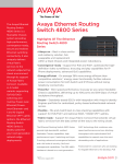
Power and Ground Connections
Each DC PEM has an earth ground connection and two DC power input connections (Input 1 and Input 2). Both external DC
inputs must be connected as shown in Figure 13. Input 1 and Input 2 are individual power inputs. Both power inputs on the
PEM must be wired to external power for the Cisco RFGW-10 to operate properly. If both inputs are not connected to external
power, the Cisco RFGW-10 will not power on.
The exposed portions of the power lugs must be covered with heat shrink tubing prior to installation.
Figure 13
DC PEM Faceplate
273170
Caution
Connect the Console and Management Ports
Each Supervisor card has an Ethernet console and a 10/100 management port for connection to a console.
Note
To meet FCC requirements, Ferrite clamps are recommended for both the console and the auxiliary cables for the
supervisor cards. The ferrites should be placed as close as possible to the RJ-45 connectors on the supervisor card. These
ferrites are included in the accessory kit.
Console Port
The console port provides local administrative access to the router and its command-line interface (CLI).
19
Step 1
Connect one end of the RJ-45 crossover cable to the RJ-45 port (labeled CONSOLE) on the supervisor.
Step 2
Connect the other end of the cable to the appropriate port on the PC or terminal to complete the console port cable
connection.
Management Port
The management port provides an Ethernet port to a LAN for a 10BASE-T and 100BASE-T connection for network
management.
Step 1
Connect one end of the RJ-45 Ethernet cable to the RJ-45 port (labelled Management on the supervisor card).
Step 2
Connect the other end of the cable to the appropriate port on the PC or console to complete the management port cable
connection.
Cabling the Cisco RFGW-10 UEQAM
The following tools are required for the Cisco RFGW-10 coaxial termination:
• 12 universal cable holders UCH2 (supplied in the accessory kit)
• T-10 TORX driver tool
• ¼” flat head screwdriver
• MCX terminated cable bundle (optional)
Figure 14
Universal Cable Holder UCH2
Red line
Small pin
TORX screw
Cutout
Lock bar
Screws into
faceplate
Lead
screw
Cutout
TORX screw
Shroud
20
155821
Large pin
The T-10 TORX driver tool and a 1/4-inch flathead screwdriver are used to remove and install the cable bar clamp on the UCH,
and loosen the line card captive screws.
The Cisco RFGW-10 UEQAM coaxial cable interface uses 75-ohm precision miniature video cable bundled cables terminated
to 75-ohm MCX connectors. The cables come in bundles of five that will fit into the provided rear RF cable management
bracket.
Note
The Cisco RFGW-10 UEQAM coaxial termination must use quad-shielded 75-ohm precision miniature video cable.
Note
Other bundle types exist for quad-shielded 75-ohm precision miniature video cable but only the five bundle will fit into
the provided cable management bracket and allow for easy removal of the RF Switch Cards.
Figure 15
5-Bundle Quad-Shielded Cable with MCX Connectors
273862
MCX
connectors
F connectors
Caution
Note
The Cisco RFGW-10 UEQAM must be used with the provided UCH for all cable connections to the RF Switch
Card. Failure to use the UCH may cause permanent damage to the line card connectors, resulting in low or no RF
output in the downstream or low or no RF input in the upstream.
The cable used with the dense connector UCH must be 75-ohm precision miniature video cable.
Part Numbers
Table 3 lists the part numbers for the Cisco RFGW-10 UEQAM RF Switch cards, cable kits, cables, connectors, tubing, and
tools.
Table 3
Part Numbers
21
Description
Part Numbers
Cisco RFGW-10 RF switch line card
Cable kit (3m MCX to F
RFGW-10-RFSW1
cables)1
CAB-RFSW520QTPMF, Cisco Systems, Inc.
Quad-shielded 5x 5 bundle cable kit, 3 bundles with colors
R,W,B,G,Y and 2 with colors Vi,O,Bk,Gr,Br.
This cable kit will wire 2 RF switch cards of the 12.
Universal Cable Holder (UCH)
CAB-520-UCH2, Cisco Systems
UCH2
MCX fixed pin connector1
PN-MCXFPQ, White Sands Engineering2
Quad-shielded
75-ohm precision miniature video cable
YR50386, Belden, five pack
Quad-shielded five-pack (red, white, blue, green, yellow)
YR52310, Belden, five pack
Quad-shielded five-pack (violet, orange, black, gray, brown)
MCX connector strip tool1
PN-CPT-7538-200Q, White Sands Engineering
Quad-shielded cables
MCX connector to F connector adapter
PN-53140137, White Sands Engineering
F connector strip tool
PN-CPT7538Q
Quad-shielded cables
MCX and F connector crimper tool
F
PN-ACT- 483, White Sands Engineering
connector1
PN-ASFPQ, White Sands Engineering
Quad-shielded
1 The Cisco RFGW-10 UEQAM must use quad-shielded cables.
2 White Sands Engineering at the following URL: http://www.whitesandsengineering.com/
Note
Do not use shrink tubing with quad-shielded MCX Connectors.
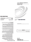
Nominal Attenuation
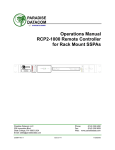
Table 4 shows the nominal attenuation for specified cable lengths.
Table 4
Nominal Attenuation for a 75-Ohm Miniature Headend Coaxial Cable
MHz
dB/100 ft
MHz
dB/100 ft
MHz
dB/100 ft
1
0.39
71
3.06
270
5.40
3.58
0.78
88
3.16
360
6.20
5
0.92
100
3.33
540
7.70
7
1.08
135
3.81
720
9.47
10
143
143
3.92
750
9.59
67.5
2.83
180
4.38
1000
10.50
22
Figure 16
Nominal Attenuation Graph for 75-Ohm Miniature Headend Coaxial Cable
NOM ATTENUATION GRAPH
0
ATTEN (dB/100-FT)
-2
-4
-6
-8
-10
-12
100
200
300
400
500
600
FREQ (MHz)
700
800
900
1000
NOM ATTEN (dB/10-0-ft)
82784
0
Installing the UCH on the Cisco RFGW-10 UEQAM RF Switch Card
Caution
The UCH must be used for all cable connections to the RF switch line card. Failure to use the UCH may cause
permanent damage to the line card connectors, resulting in low or no RF output in the downstream and low or no
RF input in the upstream.
To install the UCH, complete the following steps:
Step 1
Position the UCH red line to the red line on the RF switch card (left side see Figure 17).
Step 2
Align the end pins on the UCH with the pin holes in the faceplate.
Caution
While replacing the UCH, be careful not to bend the cables in the holder at right angles.
Step 3
While holding the UCH and the cables in place on the faceplate, use your fingers to tighten the lead screw. If the UCH
and cables do not set securely in place on the faceplate, wiggle the holder to set the connectors.
Step 4
Use the flathead screwdriver to tighten the lead screw. Turn the lead screw clockwise until it no longer turns (10 in-lbs,
maximum torque 15 in-lbs).
Caution
Note
Torquing the lead screw to more than the maximum of 20 in-lbs can cause the lead screw to fail.
For the UCH2, as you turn the lead screw clockwise, the outer shroud on the UCH moves to cover the red line on the
top and the black line on the bottom of the UCH. The half circles on the edge of the shroud close as the shroud fits
down over the UCH. Full engagement is indicated by visible metal-to-metal contact between the UCH and the faceplate
(check the half circle cutouts).
23
Figure 17
Aligning the UCH with the RF switch card Dense Connector Ports
273863
Cutout
Shroud
Red line
Lead screw
Installing the UCH on the Faceplate
273864
Figure 18
Step 5
Repeat steps 1 through 4 for the remaining 11 UCH to RF switch card interconnects.
Note
The RF switch cards connect orthogonally across all Universal RF line cards in the system picking up one connector off
each card. It is required to install all the 12 UCH to all the 12 RF switch cards so that the coaxial cables can be
connected even if only one RF line card is installed in the system.
Installing or Replacing the Cables in the UCH2
This section describes how to install and replace the UCH2 cables. The UCH2 universal cable holders must be used with the
Cisco RFGW-10 RF switch line cards. The UCH is designed to stabilize the cables and hold them in place.
24
Tools and Equipment
The tools listed below are designed to help you remove and install the cables in the UCH2.
• T-10 TORX driver tool—Removes the cable clamp bar
Note
Do not use heat-shrink wrap on quad-shielded cables.
• Cables—75-ohm quad-shielded precision miniature video cable, bonded foil 1855 type (reference YR50386 and YR52310,
Belden five pack bundles)
Installing Cables
Cisco cables are color-coded for easy reference and installation. The cable color corresponds to a specific port on the card.
See Table 5 for a list of the cable ports and its associated cable color for a five bundle quad-shielded cabling. The table includes
a column for you to define ports and color definitions.
Note
Table 5
Other color options for precision miniature video coaxial cables may be available, contact Belden for more information.
You can use any cable color combination but Table 5 is the reference color configuration.
RF Switch Universal Cable Holder Reference Color Coding
RF Switch Line Card Port
Cable Color
RFSW Slot 12
Red
RFSW Slot 11
White
RFSW Slot 10
Blue
RFSW Slot 9
Green
RFSW Slot 8
Yellow
RFSW Slot 7
Violet
RFSW Slot 6
Orange
RFSW Slot 5
Black
RFSW Slot 4
Gray
RFSW Slot 3
Brown
RF Switch User Defined
To replace cables or install new cables in an UCH2, complete the following steps:
Step 1
Use the T-10 TORX driver tool to loosen the lock bar on the side where the cable is installed.
Step 2
Use a flathead screw driver as a lever to slide open the lock bar (if needed).
Step 3
Remove the ESD cap from a cable (see Figure 19 and Figure 20) and place it in the hole in the UCH2. (See Figure 21.)
Use Table 5 to determine the correct color and location for each colored cable.
25
Removing an ESD Cap from a MCX connector
Figure 20
Removing an ESD Cap from an F connector
155825
155824
Figure 19
Step 4
Insert and wiggle the connector into the hole.
Placing Cables in the UCH2
273242
Figure 21
Note
The cables fit loosely in the holes, and are not locked into place until the lock bar is closed (Step 6).
Step 5
Repeat Step 3 and Step 4 for the remaining cables you are installing.
26
Note
Make sure the cables are aligned correctly and inserted completely otherwise the slide bar will not close.
Step 6
Slide the lock bar close completely, and use the T-10 TORX driver tool to tighten the screws clockwise (torque 10 in-lbs,
1.13 Newton meters (Nm)). The locking bar is completely closed when they are interlocked with the metal by the lead
screw.
Note
Clamp bar maximum torque 15 in-lbs (1.70 Nm)
Troubleshooting the RF Switch Card Installation
Check the following:
• Verify that the captive screws are secure.
• Verify that the card is properly seated in the chassis.
– Release the captive screws.
– Use the handle on the front of the RF switch card to disconnect the midplane connectors.
– Slide the card partially out of the chassis and then slide it back in, making sure that it is properly seated in the midplane.
– Tighten the captive screws.
• Verify that the UCH is secured in place on the faceplate.
– Check if the lead screw is secure.
Note
The recommended maximum torque that should be applied to a lead screw is 15 in-lbs (1.69 Nm).
• Verify that the connectors are properly seated in the ports on the faceplate.
– Verify that no cables are broken at the connector.
– Verify that the cables are properly secured in the UCH.
– Verify that all the MCX connectors are protruding the same distance out of the UCH.
Note
Use the MCX to F connector adapter provided in the accessory kit to easily adapt the MCX connection for testing the
cables.
• Verify that the lock bar on the UCH2 is in place and tightened.
Connecting the DTI Connections
Each TCC card has two DTI RJ-45 connectors that support an input from a DTI server (the TCC is a DTI client). These are
redundant input connections designed to support link redundancy.
27
5 Powering on the Cisco RF Gateway 10
After all network interfaces and coaxial cables are connected, perform a visual check of all connections and ensure the following:
• All captive screws on all line cards and modules should be tightened to 6-8 in-lbs.
Note
The system will not power on unless the captive screws on the DC PEM are fully engaged.
• The ejector levers on every card are in the locked position.
• All the cables are connected (power, data link, network, Ethernet).
Note
The system will not power on correctly unless both power inputs (Input 1, Input 2) are connected to the external
power source.
• The console terminal or modem is cabled and turned on.
• A compact flash card is installed in the supervisor card.
You are now ready to power on the system for the first time using the following procedure.
Step 1
Verify that each DC PEM is turned off (0).
Step 2
Remove the tape from the circuit breaker switch handle.
Step 3
Turn on power at the power supply that is suppling the DC power for the chassis.
Verifying External DC Power Source Connections
After turning on the external DC power source, verify that –48V1 and –48V2 LEDs are green (all other LEDs on the PEM should
be off). If either of these LEDs is off or the FAULT LED is red, proceed as follows:
Step 1
Turn off the external DC power source.
Step 2
Verify that the wiring from the external power source to the two power inputs (Input 1and Input 2) is connected
correctly.
Step 3
Measure the input voltage from the external power source at the –48 V1 and –48 V1 RTN terminals.
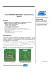
Verifying Basic System Power
• Before the chassis power is turned on, the –48V1 LED and –48V2 LED should be green. This indicates that both DC inputs
for each PEM are wired correctly to the external power source.
• Power on the chassis by switching the PEM breaker switch to the on position. At this point the OUTPUT OK LED on the
DC PEM should be green.
• The fan assembly should turn on. When power is provided to the chassis, the fans in the fan assembly module initially
operate at high speed. If all four fans are operating correctly, and if the temperature of the chassis is in the nominal operating
range, the fans slow down to their normal operating speed.
• The OK LED on the fan assembly module should be green, indicating that all fans in the blower are operating properly. You
should be able to feel the air blowing out of the upper rear of the chassis.
28
Figure 22
DC PEM LEDs
1
5
6
2
7
3
1
273687
4
8
1
DC PEM captive screws
5
Fan
2
DC PEM On (|) /Off (O) switch
6
DC PEM handle
3
Earth grounding symbol
7
DC PEM LEDs
4
DC PEM earth ground lug
8
DC PEM terminal and plastic cover
Note
With both the DC PEMs installed, both need to be operating with breaker switches on and OUTPUT OK LED on. If
one PEM is not operational, it is recommended that either the PEM be removed from the system or the power input
cables be removed to limit power supply Conductive Emissions (FCC conductive Emission Requirements).
When the power-on sequence is complete, the supervisor card begins to initialize the line cards.
29
6 Configuring the Cisco RF Gateway 10 at Startup
This section describes how to configure the Cisco RFGW-10 UEQAM the first time.
Entering the Initial Configuration Information
To set up the Cisco RFGW-10 UEQAM, you need to assign an IP address and other configuration information necessary for the
switch to communicate with the local routers and the Internet. The minimal configuration provided here does not cover feature
configuration.
Basic Configuration Using the Setup Facility
The first time you power on a Cisco RFGW-10, the setup facility starts. You can also initiate the facility by running the setup
command in privileged EXEC mode. This facility helps you enhance a default configuration that already exists on the Cisco
RFGW-10. The setup facility uses a question-and-answer sequence called the System Configuration Dialog to walk you through
the configuration.
You do not have to configure the interfaces immediately; however, you cannot enable the interfaces or connect them to any
networks until you have configured them.
Tip
Basic configuration setup is often used as a quick way to achieve network connectivity, allowing you to retrieve a
configuration file from a TFTP server.
System Configuration Dialog
Use the System Configuration Dialog to help you perform a basic configuration. Proceed through the dialog by answering
questions and then pressing the ENTER key. In most cases, you can get additional information by entering a question mark (?).
Throughout the dialog, default values are shown in square brackets ([ ]).
To cancel the configuration dialog, press CTRL-C, or you can let the dialog help you perform one of two configuration types:
• Basic configuration setup configures only enough connectivity for management of the system.
• Extended configuration setup asks you to configure each interface and is not appropriate for configuring the Cisco
RFGW-10. You can run the setup facility any time you are at the enable prompt (#) by entering the setup command.
Configuring the System Using the System Configuration Dialog
To perform a basic configuration using the System Configuration Dialog, follow this procedure:
Step 1
The dialog starts by asking if you want to continue with the configuration dialog. Enter Yes. To return to the enable
prompt, enter No.
--- System Configuration Dialog --Continue with configuration dialog? [yes/no]: yes
Step 2
Enter Yes to perform a basic management setup. Enter No to perform an extended configuration setup.
Would you like to enter basic management setup? [yes/no]: yes
Step 3
Specify a hostname. The hostname becomes part of the Cisco IOS prompt.
Enter host name [Router]: my-router
Step 4
Specify a secret password. It appears in encrypted form in the configuration file.
Enter enable secret: my_secret
Step 5
Specify the enable password. It is used if you did not assign a secret password.
Enter enable password: my_password
Step 6
Specify the password to use for Telnet sessions.
Enter virtual terminal password: my_vt
Step 7
30
At the Configure System Management prompt, enter No.
Configure System Management? [yes/no]: no
Step 8
If you want to access the router using SNMP, enter Yes at the prompt:
Configure SNMP Network Management? [yes]: yes
Step 9
Specify an SNMP community string.
Community string [public]: public
Using Configuration Mode to Configure Your Switch
To configure your switch from configuration mode, use the following procedure:
Step 1
Connect a console terminal to the console interface of your supervisor card.
Step 2
After a few seconds, you will see the user EXEC prompt (Switch>). Now, you may want to enter privileged EXEC mode,
also known as enable mode. Type enable to enter enable mode:
Switch> enable
Note
You must be in enable mode to make configuration changes.
The prompt will change to the enable prompt (#):
Switch#
Step 3
At the enable prompt (#), enter the configure terminal command to enter global configuration mode:
Switch# configure terminal
Enter configuration commands, one per line. End with CNTL/Z.
Switch(config)#
Step 4
At the global configuration mode prompt, enter the interface type slot/interface command to enter interface
configuration mode:
Switch(config)# interface fastethernet 5/1
Switch(config-if)#
Step 5
In either of these configuration modes, enter changes to the switch configuration.
Step 6
Enter the end command to exit configuration mode.
Step 7
Save your settings.
Your switch is now minimally configured and can boot with the configuration you entered. To see a list of the configuration
commands, enter ‘?’ at the prompt or press the help key in configuration mode.
Configuring a Default Gateway
Note
The switch uses the default gateway only when it is not configured with a routing protocol.
Configure a default gateway to send data to subnets other than its own when the switch is not configured with a routing
protocol. The default gateway must be the IP address of an interface on a router that is directly connected to the switch.
To configure a default gateway, perform this procedure:
Step 1
Configure a default gateway.
Switch(config)# ip default-gateway IP-address
Step 2
Verify that the default gateway is correctly displayed in the IP routing table.
Switch# show ip route
This example shows how to configure a default gateway and how to verify the configuration:
Switch# configure terminal
Enter configuration commands, one per line.
End with CNTL/Z.
31
Switch(config)# ip default-gateway 172.20.52.35
Switch(config)# end
3d17h: %SYS-5-CONFIG_I: Configured from console by console
Switch# show ip route
Default gateway is 172.20.52.35
Host
Gateway
ICMP redirect cache is empty
Last Use
Total Uses
Interface
Configuring a Static Route
If your Telnet station or SNMP network management workstation is on a different network from your switch and a routing
protocol has not been configured, you might need to add a static routing table entry for the network where your end station is
located.
To configure a static route, use this procedure:
Step 1
Configure a static route to the remote network.
Switch(config)# ip route dest_IP_address mask {forwarding_IP | vlan vlan_ID}
Step 2
Verify that the static route is displayed correctly.
Switch# show running-config
This example shows how to use the ip route command to configure a static route to a workstation at IP address 171.10.5.10 on
the switch with a subnet mask and IP address 172.20.3.35 of the forwarding router:
Switch# configure terminal
Enter configuration commands, one per line. End with CNTL/Z.
Switch(config)# ip route 171.10.5.10 255.255.255.255 172.20.3.35
Switch(config)# end
Controlling Access to Privileged EXEC Commands
The procedures in these sections let you control access to the system configuration file and privileged EXEC commands.
Setting or Changing a Static Enable Password
To set or change a static password that controls access to the enable mode, enter the enable password command:
Switch(config)# enable password password
This example shows how to configure the enable password “lab” in privileged EXEC mode:
Switch# configure terminal
Switch(config)# enable password lab
Using the enable password and enable secret Commands
To provide an additional layer of security, particularly for passwords that cross the network or that are stored on a TFTP server,
you can use either the enable password or enable secret commands. Both commands configure an encrypted password that you
must enter to access the enable mode (the default) or any other privilege level that you specify.
We recommend that you use the enable secret command.
If you configure the enable secret command, it takes precedence over the enable password command; the two commands cannot
be in effect simultaneously.
To configure the switch to require an enable password, issue either of the following commands:
Switch(config)# enable password [level level] {password | encryption-type encrypted-password}
The above command establishes a password for the privileged EXEC mode.
Switch(config)# enable secret [level level] {password | encryption-type encrypted-password}
The above command specifies a secret password that is saved using a nonreversible encryption method.
32
Note
If the enable password and enable secret commands are both set, you must enter the secret password.
When you enter either of these password commands with the level option, you define a password for a specific privilege level.
After you specify the level and set a password, give the password only to the users who need to have access at this level. Use the
privilege level configuration command to specify commands accessible at various levels.
If you enable the service password-encryption command, the password you enter is encrypted. When you display the password
with the more system:running-config command, the password displays the password in encrypted form.
If you specify an encryption type, you must provide an encrypted password—an encrypted password you copy from another
Cisco RFGW-10 UEQAM configuration.
Note
You cannot recover a lost encrypted password. You must clear NVRAM and set a new password.
Setting or Changing a Privileged Password
To set or change a privileged password, enter the password command:
Switch(config-line)# password password
Configuring FastEthernet1 Port
The supervisor includes an out of band management Ethernet port on the front panel known as “fa1”. This FastEthernet port
on the management supervisor is enabled using the following command in the ROMMON mode:
fa1Enable=1
This enables the management port after reload. When the interface is enabled, it is available via Cisco IOS.
interface FastEthernet1
ip address 10.5.30.183 255.255.255.0
speed auto
duplex auto
To disable this port, fa1Enable should be set to zero in the ROMMON mode.
Caution
Note
The FastEthernet port is not intended for heavy traffic load. The “fa1” port is directly connected to the Central
Processing Unit (CPU) and hence, the traffic on this port adversely affects the CPU’s performance. Do not use this
port for data traffic under any circumstance. The CPU is an easy target for Denial-of-Service attacks through this
port. You must ensure that the “fa1” port is restricted to management traffic only when you build your network
topology.
If the “fa1” port is enabled, the system displays a warning message during bootup.
33
7 Troubleshooting
The following section provides troubleshooting tips that you can use to verify your system setup.
Before You Call for Technical Assistance
If you are unable to solve the problem easily, contact a Cisco customer service representative for assistance and further
instructions. See the “Obtaining Documentation and Submitting a Service Request” section on page 35. Provide the
representative with the following information:
• Date you received the chassis
• Chassis serial number
• Type of software and release number
• Brief description of the problem you are having
• Brief explanation of the steps you have taken to isolate and resolve the problem
• Maintenance agreement or warranty information
Verifying Normal Startup Sequence
The LEDs indicate all system states in the startup sequence. By checking the state of the LEDs, you can determine when and
where the system failed in the startup sequence.
When you start up the system by turning the power supply switch to the ON (|) position, the following should occur:
1. Fans: The fans will start operating. The FANS OK LED on the fan assembly module will come on GREEN.
2. DC PEM: The –48V1 LED, –48V2 LED, and OUTPUT OK LED will all come on GREEN to indicate that the power supply
is connected correctly to the DC PEM for the chassis.
Note
Both DC power inputs (Input 1 and Input 2), MUST be connected to an external power source for correct operation.
3. TCC card: The POWER LED will come on GREEN. The STATUS LED is blank until the IOS is fully booted in the chassis.
When the IOS is booted, the STATUS LED will be GREEN if the TCC is the primary (active) card or will be ORANGE if
the TCC is in redundant (backup) mode. The MAINT LED is ORANGE at power up and will transition to GREEN when
the IOS is fully booted.
4. Supervisors: When the power is turned on, the STATUS LED will be ORANGE. When the IOS boots up, the STATUS LED
will turn GREEN if the supervisor is the primary (active) card or it will be ORANGE if the supervisor is in redundant
(backup) mode. The UTILIZATION LEDS will be GREEN on the primary card and blank for the redundant (backup) card.
5. RF Line Cards: At power on, the STATUS, ALARM, and TRAFFIC LEDs will be blank. As the card slot is initialized, the
STATUS LED will transition from YELLOW to GREEN, the ALARM LED will remain blank, and the TRAFFIC LED will
eventually turn GREEN.
Note
If a line card slot is configured as a redundant slot, the STATUS LED will turn BLUE.
6. RF Switch Card: The RF Switch POWER LED will be GREEN when the chassis power is turned on.
7. LCD Display: The LCD display will be blank. The LCD display information (IOS image release, Date, and so on) will not
appear until the system IOS is completely up on the chassis.
34
8 Obtaining Documentation and Submitting a Service Request
For information on obtaining documentation, submitting a service request, and gathering additional information, see the
monthly What’s New in Cisco Product Documentation, which also lists all new and revised Cisco technical documentation, at:
http://www.cisco.com/en/US/docs/general/whatsnew/whatsnew.html
Subscribe to the What’s New in Cisco Product Documentation as a Really Simple Syndication (RSS) feed and set content to be
delivered directly to your desktop using a reader application. The RSS feeds are a free service and Cisco currently supports RSS version
2.0.
35
9 Related Documents
• Cisco RF Gateway 10 Hardware Installation Guide
http://www.cisco.com/en/US/docs/cable/rf_gateway/installation/guide/rfgw10_hig.html
• Cisco RF Gateway 10 Command Reference Guide
http://www.cisco.com/en/US/docs/cable/rf_gateway/command/reference/RFGW-10_Book.html
36
37
Americas Headquarters
Asia Pacific Headquarters
Europe Headquarters
Cisco Systems, Inc.
San Jose, CA
Cisco Systems (USA) Pte. Ltd.
Singapore
Cisco Systems International BV
Amsterdam, The Netherlands
Cisco has more than 200 offices worldwide. Addresses, phone numbers, and fax numbers are listed on the
Cisco Website at http://www.cisco.com/web/siteassets/contacts/offices/index.html.
CCDE, CCENT, Cisco Eos, Cisco HealthPresence, the Cisco logo, Cisco Lumin, Cisco Nexus, Cisco StadiumVision, Cisco TelePresence, Cisco WebEx, DCE, and Welcome
to the Human Network are trademarks; Changing the Way We Work, Live, Play, and Learn and Cisco Store are service marks; and Access Registrar, Aironet, AsyncOS,
Bringing the Meeting To You, Catalyst, CCDA, CCDP, CCIE, CCIP, CCNA, CCNP, CCSP, CCVP, Cisco, the Cisco Certified Internetwork Expert logo, Cisco IOS,
Cisco Press, Cisco Systems, Cisco Systems Capital, the Cisco Systems logo, Cisco Unity, Collaboration Without Limitation, EtherFast, EtherSwitch, Event Center, Fast Step,
Follow Me Browsing, FormShare, GigaDrive, HomeLink, Internet Quotient, IOS, iPhone, iQuick Study, IronPort, the IronPort logo, LightStream, Linksys, MediaTone,
MeetingPlace, MeetingPlace Chime Sound, MGX, Networkers, Networking Academy, Network Registrar, PCNow, PIX, PowerPanels, ProConnect, ScriptShare,
SenderBase, SMARTnet, Spectrum Expert, StackWise, The Fastest Way to Increase Your Internet Quotient, TransPath, WebEx, and the WebEx logo are registered
trademarks of Cisco Systems, Inc. and/or its affiliates in the United States and certain other countries.
All other trademarks mentioned in this document or website are the property of their respective owners. The use of the word partner does not imply a partnership
relationship between Cisco and any other company. (0812R)
Any Internet Protocol (IP) addresses used in this document are not intended to be actual addresses. Any examples, command display output, and figures included in the
document are shown for illustrative purposes only. Any use of actual IP addresses in illustrative content is unintentional and coincidental.
© 2009 Cisco Systems, Inc. All rights reserved.
Printed in the USA on recycled paper containing 10% postconsumer waste.
78-18871-01