1
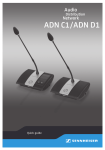
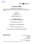
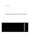
Sielox AC-1500 Controllers Series
Installation Manual
Copyright © 2006-2008 by Sielox, LLC.
Released August 2008.
Published by:
Sielox, LLC. 170 East Ninth Avenue
Runnemede, NJ 08078
Rev.: 1.0
AC-1500 Installation Manual
Introduction ............................................................................................3
Certifications ...........................................................................................3
FCC - Federal Communications Commission Notice ..................................................... 3
UL 294 and UL 1076.................................................................................................... 4
Technical Support & RMA’s ......................................................................4
Controller Features ..................................................................................5
Installing Sielox Enclosures .....................................................................6
Installing Tamper Switch ............................................................................................ 7
Mounting Plate (P/N 7372565)................................................................................... 8
Retrofit Plate Kit (P/N 7202975) ................................................................................ 9
Installation of AC-1500L Backplanes BP4, BP5 or BP7 ...........................10
Connectors and Fuses Assignment............................................................................ 11
AC-1500 Controller Modules ..................................................................13
Installing Cables into the Sielox Enclosure ............................................14
Signal Cables .........................................................................................14
Communications ....................................................................................16
Main Controller .........................................................................................................
LANLink™..................................................................................................................
X-LAN .......................................................................................................................
Installing the LAN Module.........................................................................................
Connecting the Ethernet Cable..................................................................................
Installing the RS-485 Module....................................................................................
Connecting the RS-485 Cables ..................................................................................
16
17
18
19
20
21
22
Installing the Reader Module (AC-1500-REK) ........................................23
Transient Suppressor (Door Locks and Outputs) ......................................................
Supervised Inputs.....................................................................................................
REK Connectors ........................................................................................................
Setting the Terminal Controller Address ...................................................................
Status LED CPU Board (Bottom board of the REK) ....................................................
Status LED Reader Board (Top board of REK) ...........................................................
Jumpers CPU Board (Top board of REK)....................................................................
Jumpers Reader Board (Bottom board of REK) .........................................................
RAM and Real Time Clock Backup Battery .................................................................
26
26
28
29
29
30
30
30
31
Power Cables .........................................................................................32
AC Power Surge Suppressor...................................................................................... 32
Installing the Power Regulator Module (AC-1500-PRDual) ....................33
Connecting the 12 Volts Battery ............................................................................... 34
Monitoring AC Fail..................................................................................................... 35
Page 2 of 35
AC-1500 Installation Manual
Introduction
The Sielox AC-1500 Series controllers manage access control and related events.
They are modular and scalable allowing from 2 to 8 doors and 8 to 32 I/O points on the
same backplane. With expansion, up to 256 I/O points can be monitored and controlled.
Certifications
FCC - Federal Communications Commission Notice
This equipment complies with Part 15 of the FCC rules; operation is subject to the following two
conditions:
This device may not cause harmful interference, and
This device must accept any interference received, including interference that may cause
undesired operation.
Operation of this equipment in a residential area may cause unacceptable interference to radio
and TV reception requiring the operator to take whatever steps are necessary to correct the
interference.
WARNING: Changes or modifications to Sielox’s EAC equipment not expressly approved by the
party responsible for assuring compliance could void the user’s authority to operate the
equipment in a safe or otherwise regulatory compliant manner. If equipment is not installed and
used in accordance with the instructions in the User Manual, it may cause interference; in which
case, the user at their own expense must take whatever measures are required to correct
interference.
“This Class A digital apparatus complies with Canadian ICES-003.”
«Cet appareil numérique de la classe A est conforme à la norme NMB-003 du Canada.»
Page 3 of 35
AC-1500 Installation Manual
UL 294 and UL 1076
The following are ETL certifications to UL 294 and UL 1076 standards and have been achieved on
the following 32-bit series controller sub-assembly/component providing you the flexibility of
meeting compliance requirements your final LANLink 1500 and AC-1500 Series.
LAN Controller Module: 7195578
RS-485 Module: 95310
CPU Module: 6800066
Dual Power Regulator(12V and 6V): 6800063
Reader Module: 753547
Enclosure: 7969269 (AC-1500L Series)
Input Module: 060256
Enclosure: 7106307 (AC-1500S Series)
Output Module: 361207
AC-1500 Series Backplanes: 6800067, 6800064,
6800065
AC-1508 Series Backplanes: 6800068, 7246916
For the latest ETL information list, click on the link below:
http://etlwhidirectory.etlsemko.com/WebClients/ITS/DLP/products.nsf/$$Search?OpenForm
Technical Support & RMA’s
Phone: 800-424-2126, prompt 8
FAX: 856-939-9306
8:30 am – 7:30 pm Eastern time, Monday - Friday
E-Mail:[email protected]
Page 4 of 35
AC-1500 Installation Manual
Controller Features
The Sielox AC-1500 Controller Series is powered by a 32-bit microcontroller. It comes with a built
in power regulator/UPS/Battery charger module (PR-DUAL) that keeps the unit running in the
event of a power failure.
Each controller has the following features:
• 2 doors, 2 Request to Exit, 2 Door Contacts and Door Locks.
• 50,000 Card holder database
• 10,000 Off-line events
• 4 General purpose Inputs (Supervised or Unsupervised)
• 4 General purpose Outputs
• Real Time Clock (RTC)
• Lithium Battery Backup keeps the card holder database, off-line events and RTC running in
case of power loss.
• Status Lights (Lithium Battery, Communications and power)
The AC-1500 comes in two sizes AC-1500L or AC-1500S.
The AC-1500L has 3 backplanes configurations:
• AC-1500-BP4L a 2-8 door configuration with expansion to up 4 BP7 I/O Backplanes.
• AC-1500-BP5 RIO a 2 door and I/O.
• AC-1500-BP7 I/O backplane.
The AC-1500 Series has large and small backplanes:
Large Backplanes
AC-1500-BP4L
AC-1500-BP5 RIO
AC-1500-BP7 I/O
8 readers
2 readers and 4 I/O Modules (32 I/O)
7 I/O modules (56 I/O)
Small Backplanes
AC-1500-BP2S
AC-1500-BP4S
4 readers
2 readers and 4 I/O Modules (32 I/O)
Page 5 of 35
AC-1500 Installation Manual
Installing Sielox Enclosures
Sielox provides 2 types of enclosures:
•
•
Large Enclosure p/n 7969269 for large backplanes
Small Enclosure p/n 7106307 for small backplanes
To install the Sielox enclosures, perform the following procedure:
1. Position the enclosure or template at the desired installation location and mark the four
keyhole slot locations for mounting.
2. Install the applicable mounting fasteners such as wood screws, moly bolts, or masonry
fasteners, but do not tighten them completely.
3. Position the enclosure on the four fasteners and tighten them completely.
4. Install the conduit, if not already completed.
5. Install a grounding lug to the Enclosure; ensure that the lug is terminated to an earth
ground.
6. Clean any debris from the enclosure.
Large Enclosure p/n 7969269
Small Enclosure p/n 7106307
Page 6 of 35
AC-1500 Installation Manual
Installing Tamper Switch
A Tamper Switch mounting channel is available in the upper right hand corner of the large
enclosure p/n 7969269 or in the lower right hand corner of the small enclosure p/n
7106307. The switch provided by Sielox will be installed in this mounting channel.
The Tamper Switch must be connected to an Input of an installed controller. This input
shall be configured as normally closed with supervision. Two supervisory resistors
(5.1KOhm) shall be inserted in the wiring from the switch to the terminal controller, one
across the contact of the switch, the other in the Signal data line to the controller. When
configured and connected in this way, the controller will properly report an Input Active
event when the enclosure door is open and Input Secure when the door is closed.
An Input Cut or Input Shorted status will be reported if the switch or supervision resistors
are not properly assembled and connected.
Please refer to the following drawing for wiring of the Tamper Switch:
Input
Return
5.1k Ohm EOL
Tamper Switch
Page 7 of 35
AC-1500 Installation Manual
Mounting Plate (P/N 7372565)
The AC-1200-MAP mounting plate can be used where an AC-1500 is not being installed in
the AC-1200-ENC-32 Enclosure.
Not evaluated by UL (The AC-1200-MAP has not been evaluated by UL and is not UL294
compliant. Use the AC-1200-ENCL for UL294 compliance.)
Page 8 of 35
AC-1500 Installation Manual
Retrofit Plate Kit (P/N 7202975)
AC-1200-RFK (Retrofit Plate Kit).
Not evaluated by UL (The AC-1200-RFK has not been evaluated by UL and is not UL294
compliant. Use the AC-1200-ENCS for UL294 compliance.)
Page 9 of 35
AC-1500 Installation Manual
Installation of AC-1500L Backplanes BP4, BP5 or BP7
In order to mount the AC-1500 series of backplanes into the enclosure or mounting plate,
12 SEMS screws #6-32 x 5/16 must be used. The enclosure and the mounting plate have
threaded studs for the utilization of these screws. The AC-1500 series backplanes have
circular cutouts that allow these screws to be utilized, thereby securing the printed circuit
board into the enclosure.
The AC-1500 series of backplanes, when purchased, are shipped with all hardware
necessary for mounting the backplane to the enclosure.
Mounting Holes
Mounting Holes
AC-1500L BP4 Mounting Holes
Page 10 of 35
AC-1500 Installation Manual
Connectors and Fuses Assignment
Connectors
J200/J201
J300/J301
J302/J303
J304/J305
J204/J203
J205/J206
J209/J210
J102/J101/J3
J100
J700
J306
J307
J308
J216
J211
J213
J1
J2
J215
J214
Description
AC-1500-CPU (CPU 1 slot)
AC-1500-CPU (CPU 2 slot)
AC-1500-CPU (CPU 3 slot)
AC-1500-CPU (CPU 4 slot)
AC-1200-PR5 (Used with AC-1200 only) 1
AC-LAN-COMM or AC-1500-RS485 Primary
AC-LAN-COMM or AC-1500-RS485 Secondary (Reserved)
AC-1500-PRDUAL or AC-1200-PR12 (Used with AC-1200 only)
DC-IN +11.5 to +25 VDC with AC-1500-PRDUAL
Connection to I/O Backplane 1
Connection to I/O Backplane 2
Connection to I/O Backplane 3
Connection to I/O Backplane 4
Battery connection for CPU memory retention AC-1200 Only 3
RS485 Connection Primary Channel
RS485 Connection Secondary Channel (Reserved) 4
External 5.8-6.0 VDC Input
External 12 VDC Input
Loop connection for controller supervision
MODEM Connection
2
Notes:
Some connectors were left on this backplane for backward compatibility with the AC-1200 Series.
The PRDUAL is a 6 Volts, 12 Volts and battery charger it replaces both PR5 and PR12.
1. AC-1200-PR5 is not used with AC-1500.
2. AC-1200-PR12 is not used with AC-1500.
3. This External 6 Volt battery is not use with AC-1500 Reader Modules (REK).
4. The Secondary channel is reserved for communication between the AC-1500 Main
Controller and Pinnacle hardware server.
Fuses
F1
F2
F3
Description
DC-IN Fuse 5 Amp / 125 Volts
5.8V Direct Fuse 5 Amp / 125 Volts
12V Direct Fuse 5 Amp / 125 Volts
Page 11 of 35
AC-1500 Installation Manual
AC-1500L BP4 Connectors and Fuses location
Page 12 of 35
AC-1500 Installation Manual
AC-1500 Controller Modules
AC-1500-CPU
CPU Module (Requires AC-1500-RDR)
Capacity of
•
Real Time Clock (RTC)
•
Data and RTC Battery Backup
•
50K Cards
•
10K off-line events
AC-1500-OUT
Output Module
•
8 Outputs
(Relays- C, NO,NC)
AC-1500-RDR
Reader
•
•
•
•
•
•
Module (requires AC-1500-CPU)
2 Readers
2 Door Contacts
2 Door Strikes
2 REX
4 Inputs
(Supervised/Unsupervised)
4 Outputs (relays- C, NO,NC)
AC-LAN-COMM
LANLink™ Controller Module
AC-1500-REK (Terminal Controller)
This module is a combination of the
AC-1500-CPU and AC-1500-RDR.
The AC-1500-RDR plugs on top of the
AC-1500-CPU.
AC-1500-RS485
RS-485 Controller Module
AC-1500-PRDUAL
AC-1500-INP
Input Module
•
8 Inputs (Sup/Unsupervised)
12 VDC & 6 VDC Power
Regulator / Battery Charger
and AC-Fail status.
Required with backplanes:
•
AC-1500-BP2
•
AC-1500-BP4L
•
AC-1500-BP4S I/O
•
AC-1500-BP5 RIO
•
AC-1500-BP7 I/O
AC-1500 Modules Table
Page 13 of 35
AC-1500 Installation Manual
Installing Cables into the Sielox Enclosure
Signal Cables
Connect signal cables to any reader, door strike, output, input, request-to-exit and door
switch. Follow these procedures:
1. Pull signal cables through the Sielox Enclosure. (See table below)
2. When connecting these cables to the AC-1500 reader, input or output modules,
form a cable bundle using plastic cable ties (Tie wraps).
3. Arrange conductors so that they split out at the right angles from the bundle. Allow
enough slack so that the enclosure door can shut easily without pinching the cable
bundle.
4. Strip ¼ inch of insulation from each conductor that inserts into a connector block.
5. Insert the stripped conductors into respective removable connectors and tighten set
screws.(See REK Connectors and AC-1500L BP4 Connectors details)
6. Verify cable connections.
7. Insert removable connectors on the appropriate module fixed connector.
Cable Type
Belden 8761
(Shielded)
Belden 9460
(Shielded)
West Penn
5304E
(Shielded)
AWG
Wires
Where Used
22
2
Inputs (Door, REX)
Clear / Black
500 ft.
18
2
Outputs (Door Lock)
Clear / Black
*
18
5
Wiegand Readers
Red/Black/White/Green/Brown
500 ft.
Red/Black/White/Green
Red/Black
4000 ft.
50 ft.
Belden 8723
(Shielded)
22
4
Communication RS-485
Belden 1307A 16
2
Power / Battery
*Application dependent but typically runs 500 ft.
Color Code
AC-1500 Cables
Page 14 of 35
Max. Dist.
AC-1500 Installation Manual
AC-1500 Typical Wiring
Field wires connected to a Terminal Controller
Page 15 of 35
AC-1500 Installation Manual
Communications
The AC-1500 controller communicates directly to a Pinnacle Hardware Server via Ethernet
or a combination of Ethernet and RS-485.
The AC-1500 controller communicates to an AC-900 Main Controller via RS-485, the AC1500 LANLink™ provides an Ethernet connection to the controller’s backplane.
The X-LAN device provides an external Ethernet to RS-485 conversion. The
communication interface at the Pinnacle Server is Ethernet. The communication interface
at the controller’s backplane is RS-485.
Main Controller
The Main Controller (MC) is connected to the Pinnacle Hardware Server through an AC-IF2,
which is an RS-232 to RS-485 converter.
Many computer manufacturers no longer provide RS-232 serial communication ports. In
these situations, an AC-IFUSB adapter can be used for USB to RS-232 conversion and
connection to the AC-IF2.
Pinnacle Hardware Server
AC-IF2
RS-232
AC-IFUSB
AC-900
Main Controller &
Terminal Controller 1
RS-485
USB
AC-1500L
Terminal Controllers from 2 to 16
(Note: The last backplane has 3 TC’s. A total of 16 TC’s
including one on the Main Controller)
RS-485
Page 16 of 35
AC-1500 Installation Manual
LANLink™
LANLink™ is Sielox’s IP-based access control controller, also known as the LAN Controller
(LC), with 2 to 8 doors per LC.
Pinnacle Hardware Server
Network Switch
Ethernet
AC-1500 LANLink™
4 or 2 Terminal Controllers per Ethernet Connection
LANLink 1500L
(Main Controller is not required)
2 To 8 Doors
LANLink 1500S
2 to 4 Doors
Ethernet
Page 17 of 35
AC-1500 Installation Manual
X-LAN
X-LAN is an Ethernet to RS-485 converter. The X-LAN does not require a Main controller
and allows up to 16 TC’s (4 fully populated BP4 backplanes) per Ethernet connection.
The X-LAN is an ideal solution for installations with existing Ethernet Network
infrastructure, because it reduces installation cost.
Note: The XLAN will be available on the third quarter of 2007 and requires
Pinnacle 6.1.xx software.
Pinnacle Hardware Server
Ethernet
Network
Ethernet
X-LAN
AC-1500L
Up to16 Terminal Controllers
(Main Controller is not required)
RS-485
Page 18 of 35
AC-1500 Installation Manual
Installing the LAN Module
Plug the AC-LAN-COMM module to connectors J205 and J206 (RS 485 Primary) located on
the backplane. (See Backplane Connector Locations and AC-1500 Modules Table).
Proper orientation must be observed when installing the module into the connectors, see
figures below.
Backplane Bottom View
AC-LAN-COMM Module Installed
Page 19 of 35
AC-1500 Installation Manual
Connecting the Ethernet Cable
1. Pull the communication cable through the Sielox Enclosure. (See table below)
2. Terminate the CAT5 cable with an RJ-45 connector.
3. Connect the RJ-45 connector to the AC-LAN-COMM.
Cable Type
AWG
Wires
Where Used
Color Code
Max. Dist.
Belden 11700A
24
8
Ethernet Communication
Orange/Blue/Green/Brown
Striped Orange/Blue/Green/Brown
329 ft.
Page 20 of 35
AC-1500 Installation Manual
Installing the RS-485 Module
In order to use this interface you have to plug in the AC-1500-RS485 module to
connectors J205 and J206 (RS 485 Primary) located on the backplane. (See Backplane
Connector Locations and AC-1500 Modules Table). Proper orientation must be observed
when installing the module into the connectors, see figures below.
Backplane Bottom View
AC-1500-RS485 Module Installed
Page 21 of 35
AC-1500 Installation Manual
Connecting the RS-485 Cables
4. Pull the communication cable through the Sielox Enclosure. (See table below)
5. Insert the stripped conductors into the removable RS-485 P (J211) connector and
tighten set screws.
6. Observe the polarity.
7. Insert removable connector on the J211 connector.
Cable Type
AWG
Wires
Where Used
Color Code
Max. Dist.
Belden 8723
(Shielded)
22
4
Communication RS-485
Red/Black/White/Green
4000 ft.
Page 22 of 35
AC-1500 Installation Manual
Installing the Reader Module (AC-1500-REK)
The AC-1500-REK is also know as Terminal Controller (TC).
Plug in the AC-1500-REK reader module to connectors J200 and J201 (CPU 1) located on
the backplane. (See Backplane Connector Locations and AC-1500 Modules Table). Proper
orientation must be observed when installing the module into the connectors, see figure
below.
Repeat the above procedure for all the additional CPU module, plug:
o
o
o
AC-1500-REK reader module to connectors J300 and J301 (CPU 2)
AC-1500-REK reader module to connectors J302 and J303 (CPU 3)
AC-1500-REK reader module to connectors J304 and J305 (CPU 4)
AC-1500L Backplanes with 1 and 4 AC-1500-REK Modules installed
Page 23 of 35
AC-1500 Installation Manual
Page 24 of 35
AC-1500 Installation Manual
Connect signal cables to any reader, door strike, output, input, requestto-exit and door switch. Follow these procedures:
1. Pull signal cables through the Sielox Enclosure. (See table below)
2. When connecting these cables to the AC-1500 reader, input or output modules,
form a cable bundle using plastic cable ties (Tie wraps).
3. Arrange conductors so that they split out at the right angles from the bundle. Allow
enough slack so that the enclosure door can shut easily without pinching the cable
bundle.
4. Strip ¼ inch of insulation from each conductor that inserts into a connector block.
5. Insert the stripped conductors into respective removable connectors and tighten set
screws.(See modules for connector details)
6. Verify cable connections.
7. Insert removable connectors on the appropriate module fixed connector.
Cable Type
Belden 8761
(Shielded)
AWG
Wires
22
2
Where Used
Inputs (Door, REX)
Belden 9460
(Shielded)
18
2
Outputs (Door Lock)
West Penn
5304E
(Shielded)
18
5
Wiegand Readers
*Application dependent but typically runs 500 ft.
Color Code
Max. Dist.
Clear / Black
500 ft.
Clear / Black
*
Red/Black/White/Green/Brown
500 ft.
Note: See the figure AC-1500-REK Connectors.
Page 25 of 35
AC-1500 Installation Manual
Transient Suppressor (Door Locks and Outputs)
The installation of suppression diodes is required for all electric door locks or other
inductive loads connected to TC outputs. See diagram below.
Connect to J11 or
J12 (REK), NO or
NC pins. *
Connect to Door
Strike Power Supply
Ground
Color band
denotes
Cathode
+
-
Diode required
Type 1N4004
Electric Lock
or
Inductive Load
*Note1: Use N.O. when using Maglock. (Fail Safe)
Note2: Use N.C. when using Electric Strike (Fail Secure)
Supervised Inputs
All the REK inputs can be supervised including the door contact.
Install two 5.1K Ohm, 5% End-Of-Line resistors as close as possible to the switch.
One resistor is connected in parallel with the switch contacts and the other in series with
one contact.
Normally Open or Normally Closed
Door Switch / Dry Contact.
Input
Return
5.1k Ohm EOL
Note: Remember to configure the Door Properties or Inputs Properties in Pinnacle
Device Setup for the proper switch state and supervision.
Page 26 of 35
AC-1500 Installation Manual
J8 - Reader 2
Voltage Selector
J7 - Reader 1
Voltage Selector
+5V
+5V
+12V
+12V
J9 - Reader 2
J1 - Reader 1
J10 - Output 4
J2,J3,J4 –
Outputs 1, 2 & 3
J11 - Door Strike 1
J12 Door Strike 2
J13, J14 - Inputs
1,2,3 & 4
J5 - Request-To-Exit
1&2
Clear RAM
Push Button
J6 - Door Contact 1
&2
DS1 & DS2
Status LEDs
J21 - Maintenance
Port
Secondary Comm Port 1
Status LEDs
RAM Lithium
Battery
RESET Push
Button
5V, Fault & 12 V
Status LEDs
Primary Comm Port 0
Status LEDs
AC-1500-REK Connectors, Jumpers, LED’s and Push Buttons
DS1 - LED
DS4 - LED
DS2 - LED
DS5 - LED
DS3 - LED
DS6 - LED
J12 – ON/OFF
ON
OFF
SW1 – Address Rotary Switch
AC-1500-REK Jumper, Output LED’s and Address Switch
Page 27 of 35
AC-1500 Installation Manual
REK Connectors
Readers 1 & 2 - J1 & J9
PIN
Name
Wire Color
SND BLU Sounder* Blue
GND BLK Ground
Black
PWR RED Power**
Red
1 WHT
Data 1
White
0 GRN
Data 0
Green
LED BRN LED
Brown
* For use with AC-125 series of Performa readers.
** Reader voltage 5VDC or 12 VDC is selectable, see J7.
Door Contacts 1 & 2 Connectors J6
PIN
DOOR1
RET
DOOR2
RET
Name
Signal
Ground
Signal
Data 1
Wire Color
Clear
Black
Clear
White
Door REX (Request to Exit) 1 & 2 - J5
PIN
REX1
RET
REX2
RET
Name
Signal
Ground
Signal
Data 1
Wire Color
Clear
Black
Clear
White
Door Strike 1 & 2 - J11 & J12
PIN
NO
COM
NC
Name
Normally Open
Common
Normally Closed
Wire Color
Any
Any
Any
Outputs 1, 2, 3 & 4 - J2, J3, J4 & J10
PIN
NC
COM
NO
Name
Normally Closed
Common
Normally Open
Wire Color
Any
Any
Any
Inputs 1 & 2 - J13
PIN
RET
IN1
RET
IN2
Name
Ground
Signal
Ground
Signal
Inputs 3 & 4 Connector - J14
Wire Color
Black
Clear
Black
Clear
PIN
RET
IN3
RET
IN4
Name
Ground
Signal
Ground
Signal
Page 28 of 35
Wire Color
Black
Clear
Black
Clear
AC-1500 Installation Manual
Setting the Terminal Controller Address
Each Terminal Controller (TC) needs a unique address.
Locate the SW1 rotary switch on the REK. (See REK Address Switch )
SW1 Position
0
1
2
3
4
5
6
7
8
9
A
B
C
D
E
F
TC Address
1
2
3
4
5
6
7
8
9
10
11
12
13
14
15
16
Notes: If using a Main Controller the address of the first TC has to be 2 or higher,
the MC is also a TC and it uses address 1.
Status LED CPU Board (Bottom board of the REK)
LED
Description
Lithium Battery
DS2
ON = Battery Good. OFF=Battery low or missing
Power Indicators
DS3 (+5)
ON =6 Volts present
DS4 (F)
ON = Fault
DS5 (+12)
ON=12 Volts present
Primary Communication Channel – Host or Main Controller
DS6 (EN0)
Transmit Enable
DS7 (TX0)
ON= Transmitting Data
DS8 (RX0)
ON=Receiving Data
Secondary Communication Channel *
DS9 (EN1)
Transmit Enable
DS10 (TX2) Transmit Data
DS11 (RX3) Receive Data
* This channel is reserved for future use.
Page 29 of 35
AC-1500 Installation Manual
Status LED Reader Board (Top board of REK)
LED
Outputs
DS1
Indicates
DS2
Indicates
DS3
Indicates
DS4
Indicates
Door Strike
DS5
Indicates
DS6
Indicates
Description
output
output
output
output
1
2
3
4
(OUT1)
(OUT2)
(OUT3)
(OUT4)
is
is
is
is
in
in
in
in
the
the
the
the
energized
energized
energized
energized
state
state
state
state
when
when
when
when
lit.
lit.
lit.
lit.
strike 1 (STRIKE1) is in the energized state when lit.
strike 2 (STRIKE2) is in the energized state when lit.
Jumpers CPU Board (Top board of REK)
LED
J7
J8
Description
Reader 1 voltage selector
Reader 2 voltage selector
+12V
+5V
Jumpers Reader Board (Bottom board of REK)
LED
J12
Description
CPU Power (5 Volts)
ON
OFF
Page 30 of 35
AC-1500 Installation Manual
RAM and Real Time Clock Backup Battery
The AC-1500-REK has a Lithium battery which holds the TC database, transactions and
Real Time Clock in the event of AC power loss. This battery needs to be checked on annual
basis by the field technician with a voltmeter, during preventive maintenance.
Follow these procedures to check the battery voltage and replace it if needed:
1. Turn off the main power of the backplane by removing the DC-IN connector.
2. With a digital voltmeter, measure the battery voltage on board. (Do not remove the
battery from the socket)
3. The voltage should be between 2.7 to 3 volts.
4. Replace the battery if below 2.7 volts.
CAUTION
Danger of explosion if battery is incorrectly replaced.
Replace only with the same or equivalent type recommended by the manufacturer.
Dispose of used batteries in accordance with the manufacturer instructions.
Battery type: Lithium Battery PANASONIC BR2032.
Page 31 of 35
AC-1500 Installation Manual
Power Cables
To connect the power cables to the AC-1500 backplane:
1. Pull power cable through the Sielox Enclosure. (See table below)
2. Insert the stripped conductors into the removable DC-IN (J100) connector and tighten
set screws.
3. Observe the polarity.
4. Insert removable connector on the J100 connector.
Cable Type
Belden 1307A
AWG
16
Wires
2
Where Used
Power / Battery
Color Code
Red/Black
Max. Dist.
50 ft.
DC-IN Connection
AC Power Surge Suppressor
Sielox highly recommends the use of an AC power surge suppressor such as Ditek-1F.
For more information go to http://www.ditekcorp.com/product-details.asp?ProdKey=11
Page 32 of 35
AC-1500 Installation Manual
Installing the Power Regulator Module (AC-1500-PRDual)
This Sielox module is a voltage regulator and UPS (Uninterruptible Power Supply) when
connected to an external sealed lead acid battery. The AC-1500-PRDUAL has the following
features:
• 12 VDC and 6 VDC regulator
• Built-in battery charger ( 12 VDC / 7 AMP Hour sealed lead acid)
• Battery charge indicator (20%, 40%, 60%, 80% and 100%)
• Trouble LED indicator
• Protection fuses F1 and F2
DS1
DS2
DS3
F1 – 5A
F2 – 5A
DS9-DS14
A-1500-PRDual - Front
AC-1500-PRDual - Back
Wire Pigtail Table
Fuse
Description
White
* AC Fail Status. (0 Volts=AC OK. 5 Volts=AC Fail)
Black
Battery Negative - pole
Red
Battery Positive + pole
* Open Collector limited to 100mA/24 Volts DC
LED Function Table
LED
DS1
DS2
DS3
DS9
DS14, DS13, DS12, DS11 and DS10
Description
12 Volts Indicator (ON=12VDC OK. OFF=No voltage)
6 Volts Indicator (ON=6VDC OK. OFF=No voltage)
DC In Indicator (ON=DC In OK. OFF=No voltage
Trouble Indicator (ON=No trouble. OFF=AC Fail or Battery
not charging or not connected)
Battery Charge indicators 20%, 40%, 60%, 80% and 100%
Page 33 of 35
AC-1500 Installation Manual
Fuses Table
Fuse
F1
F2
Description
DC In Fuse (5 Amp)
Battery Fuse (5 Amp)
Plug in the AC-1500-PRDual module to connectors J101 and J102 (PR12) located on the
backplane (See Backplane Connector Locations and AC-1500 Modules Table).
Proper orientation must be observed when installing the module into the connectors, see
figures below.
AC1500-PRDual
Connecting the 12 Volts Battery
The AC-1500-PRDual module comes with a wire pigtail, white, black and red. Connect the
black wire spade lug to the battery negative (-) pole and the red wire spade lug to the
battery positive (+) pole.
Page 34 of 35
AC-1500 Installation Manual
Monitoring AC Fail
If you want to monitor AC fail connect the white wire to one of the available TC inputs.
Note: You have to configure the input “Secure State” under Input Properties in Pinnacle as
well the input description. See Pinnacle User Manual for more information.
AC-Fail Input Secure State
AC-Fail Input Description
Page 35 of 35