1
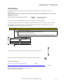
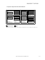
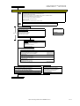
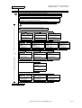
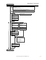
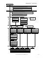
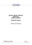
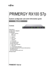
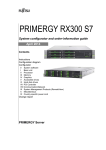
PRIMERGY BX920 S3
System configurator and order-information guide
July 2012
Contents
Instructions
Configuration diagram
Configurator
0
#
#
#
#
#
#
#
System software
X
XI
XII
XIII
XIV
XV
XVI
BX920 S3 Dual Socket
Processor
Memory
Storage
RAID Functionality
20
iRMC S3, Graphics
25
Mezzanine Cards
26
L
LI
LII
LIII
Storage Blades
SX910 Tape Blade
SX910 SAS Controller
SX910 SAS Tape Drive
# LIV
# LV
# LVI
21
22
23
24
XX
XXI
XXII
XXIII
XXIV
XXV
XXVI
#
#
#
#
#
Change report
PRIMERGY Server
SX940 Storage Blade Disk
SX940 SAS Controller
SX940 Quad Disk Blade
System configurator and order-information guide
PRIMERGY BX920 S3
Status: 2012-06-29
Instructions
This document contains basic product and configuration information that will enable you to configure your system via
System-Architect.
Only the tool "System-Arcitect" will ensure a fast and proper configuration of your PRIMERGY server or your complete
PRIMERGY Rack system.
Please pay attention to the naming conventions:
BX900 S1
BX920 S2
System unit 1nd generation
Dual Server Blade S2
You can configure your individual PRIMERGY server in order to adjust your specific requirements.
The System configurator is divided into several chapters that are identical to the current price list and PC-/ System-Architect.
Please follow the lines. If there is a junction, you can choose which way or component you would like to take. Go through
the configurator by following the lines from the top to the bottom.
Section
IV
Memory, example
There are 3 free memory banks available.
The memory banks can be populated with 512MB, 1GB, 2GB and 4GB DDR Memory.
The maximum total amount of memory is 12GB.
It is possible to select memory upgrade options up to 3 times.
ECC with memory scrubbing-function and hot-spare memorybank is standard on the PRIMERGY BX600 S2 Server Blades.
S26361-XXX-XXX
Memory XXX MB
S26361-XXX-XXX
Memory XXX MB
max. X times per system
max. X times per system
X times
In one chapter you can only select as many components (here 3x) as the arrow indicates.
3x
Please note that there are information symbols which indicate necessary information.
For further information see:
http://ts.fujitsu.com/products/standard_servers/index.html
(internet)
https://partners.ts.fujitsu.com/com/order-supply/configurators/primergy_config/Pages/Currentconfigurators.aspx
(extranet)
Prices and availability see price list and PC-/ System-Architect
Subject to change and errors excepted
Fujitsu Technology Solutions x86 PRIMERGY Server
2 of 14
System configurator and order-information guide
PRIMERGY BX920 S3
Status: 2012-06-29
Configuration diagram Dual Server Blade BX920 S3
Mezzanine slot 1
CPU1
Row 1
(3 DIMMS)
Row 2
(3 DIMMS)
Intel CPU
First Mezz. card
or
unpopulated
Mezzanine slot 2
CPU2
Row 1
(3 DIMMS)
Intel CPU
Row 2
(3 DIMMS)
upper
SAS 2.5"
or HDD dummy frame
lower
SAS 2.5"
or HDD dummy frame
Disk drives
LSI HW Raid Ctrl.
Second Mezz. card
or
unpopulated
Flash Backup Unit
PCH SAS upgrade
UFM
Processor
Memory
Mezzanine slot
Storage Options
Key:
Included in basic unit
Option
The population order for the CPU is: CPU1 first, then CPU2
The population order for the DIMMs: for each CPU, the DIMM row 1 (DIMMS 1A 1B 1C) (DIMMS 1D 1E 1F) first, then row 2 (DIMMs 2A, 2B, 2C) (DIMMs 2D, 2E, 2F)
Fujitsu Technology Solutions x86 PRIMERGY Server
3 of 14
System configurator and order-information guide
PRIMERGY BX920 S3
Status: 2012-06-29
D
Section
X
Dual Socket Server Blade BX920 S3
Server Blade with:
- Dual INTEL Romley Processor Support as Dual/Quad/Six-Core
- The base units with INTEL Processor
- 12 DIMM sockets, organized in 2 row (6 DIMM) for CPU1 and 2 row (6 DIMM) for CPU2
- 1x Dual channel 10 Gbit Ethernet CNA controller on-board
- Hard disk controller for the 2x SAS/SATA HDD/SSD
- 2 bays for 2.5" SAS hard disks (hot-plug)
- iRMC S3 on-board
- Special connector for Y-cable (4x USB, 1 x serial 1x VGA).
The BX920 S3 Server Blade can be installed max. 18x in the BX900 S1 System Unit
S26361-K1406-V200
S26361-F4478-L2
PY BX900 Y-Cable frontside
PY BX920 S3 Dual Server Blade
max. 18x
up to 2x 2.5" SAS/SATA hard disk drives.
Dual Server Blade Base Unit without
for KVM connection to
CPU and without memory modules!
2x USB, 1x VGA
Server Blade
PY BX920 S3 Dual Server Blade
For CPU and Memory configuration see section XLI.
Max. 18x per BX900 System Unit.
S26361-F3552-E1
TPM Module
Trusted Platform Module on motherboard
PY TPM Module
Be aware of import restrictions!
Max. 1x per Server Blade.
Following USB Components are available
1) USB DVD SM / Blu-Ray
External SuperMulti Drive (as soon as available)
External Blu-Ray Drive (as soon as available)
S26341-F103-L119
S26341-F103-L120
S26381-K340-V120
2) USB Keyboard:
KBPC PX D, professional keyboard
S26381-K415-L100
3) USB Mouse:
Optical Wheel Mouse Tilt USB/PS2
4) USB Memorybird:
MyUSBS
MyUSB P910
A9108GB
8GB,
(as
MLC
soon
Flash
as available)
S26391-F6048-L208
MyUSBS
MyUSB P910
A9108GB
16GB,
(asMLC
soonFlash
as available)
S26391-F6048-L216
S26361-F2749-E1
S26361-F2749-E2
Service for Server Blade installation in the System Unit.
Server Blade individually packed / delivered.
Hereby the BX900 S1 will be delivered completely
The Server Blade is not built in a BX900 S1,
configured and tested with Server Blades integrated.
it is separately tested and delivered.
This order number must be in the same order as the System Unit itself.
min. 1x per System Unit; max. 18x per System Unit; max. 1x per Server Blade
Contains ServerStart CD
max. 1x per Server Blade
E
Fujitsu Technology Solutions x86 PRIMERGY Server
4 of 14
System configurator and order-information guide
PRIMERGY BX920 S3
Status: 2012-06-29
E
XI
Section
Processor
There are 2 processor sockets available.
The first socket is always equipped with the first CPU which can be selected via configurator
It is also possible to upgrade a dual-processor system later on with a second CPU
For the second CPU there are different order numbers, due to the different Heatsink.
Two processors with different clock frequencies are not possible
A multi-processor operating system is required for a dual-processor system.
Max. two CPU`s can be selected per basic unit
One of following CPU´s has to be selected as first CPU
for an orderable basic unit
Optional second CPU has to be the same type like the first CPU
Basic 4C CPU's
- 1x 64-bit Intel Xeon (10MB shared TLC = Third Level Cache )
1066 MHz DDR3 Bus, 6,40 GT/s QPI Bus and passive heat sink
occupies socket for one CPU
Xeon E5-2403 4C/4T 1.80GHz 10MB 6.40GT/s 1066MHz 80W
Xeon E5-2407 4C/4T 2.20GHz 10MB 6.40GT/s 1066MHz 80W
S26361-F4560-E180
S26361-F4560-E220
Standard Turbo 6C CPU's
- 1x 64-bit Intel Xeon (15MB shared TLC = Third Level Cache ); Hyper-Threading (HT);
1x
1333 MHz DDR3 Bus, 7,20 GT/s QPI Bus and passive heat sink
occupies socket for one CPU
Xeon E5-2420 6C/12T 1.90GHz 15MB 7.20GT/s 1333MHz 95W
Xeon E5-2430 6C/12T 2.20GHz 15MB 7.20GT/s 1333MHz 95W
Xeon E5-2440 6C/12T 2.40GHz 15MB 7.20GT/s 1333MHz 95W
S26361-F4561-E190
S26361-F4561-E220
S26361-F4561-E240
Advanced Turbo+ 8C CPU`s
- 1x 64-bit Intel Xeon (20MB shared TLC = Third Level Cache ); Hyper-Threading (HT);
1600 MHz DDR3 Bus, 8,00 GT/s QPI Bus and passive heat sink
occupies socket for one CPU
Xeon E5-2450 8C/16T 2.10GHz 20MB 8.00GT/s 1600MHz 95W
Xeon E5-2470 8C/16T 2.30GHz 20MB 8.00GT/s 1600MHz 95W
S26361-F4562-E210
S26361-F4562-E230
Low Power 6C/8C CPU's
- 1x 64-bit Intel Xeon (15/20MB shared TLC = Third Level Cache); Hyper-Threading (HT);
1333/1600 MHz DDR3 Bus, 8,00 GT/s QPI Bus and passive heat sink
occupies socket for one CPU
Xeon E5-2430L 6C/12T 2.00GHz 15MB 7.20GT/s 1333MHz 60W
S26361-F4563-E200
Xeon E5-2450L 8C/16T 1.80GHz 20MB 8.00GT/s 1600MHz 70W
S26361-F4563-E180
Max. two CPU`s can be selected per basic unit
One of following CPU´s has to be selected as second CPU
for an orderable basic unit
Optional second CPU has to be the same type like the first CPU
Basic 4C CPU's
- 1x 64-bit Intel Xeon (10MB shared TLC = Third Level Cache )
1066 MHz DDR3 Bus, 6,40 GT/s QPI Bus and passive heat sink
occupies socket for one CPU
Xeon E5-2403 4C/4T 1.80GHz 10MB 6.40GT/s 1066MHz 80W
S26361-F4564-E180
Xeon E5-2407 4C/4T 2.20GHz 10MB 6.40GT/s 1066MHz 80W
S26361-F4564-E220
Standard Turbo 6C CPU's
- 1x 64-bit Intel Xeon (15MB shared TLC = Third Level Cache ); Hyper-Threading (HT);
1333 MHz DDR3 Bus, 7,20 GT/s QPI Bus and passive heat sink
occupies socket for one CPU
Xeon E5-2420 6C/12T 1.90GHz 15MB 7.20GT/s 1333MHz 95W
S26361-F4565-E190
Xeon E5-2430 6C/12T 2.20GHz 15MB 7.20GT/s 1333MHz 95W
S26361-F4565-E220
Xeon E5-2440 6C/12T 2.40GHz 15MB 7.20GT/s 1333MHz 95W
S26361-F4565-E240
Advanced Turbo+ 8C CPU`s
- 1x 64-bit Intel Xeon (20MB shared TLC = Third Level Cache ); Hyper-Threading (HT);
1600 MHz DDR3 Bus, 8,00 GT/s QPI Bus and passive heat sink
occupies socket for one CPU
Xeon E5-2450 8C/16T 2.10GHz 20MB 8.00GT/s 1600MHz 95W
S26361-F4566-E210
Xeon E5-2470 8C/16T 2.30GHz 20MB 8.00GT/s 1600MHz 95W
S26361-F4566-E230
Low Power 4C/6C/8C CPU's
- 1x 64-bit Intel Xeon (15/20MB shared TLC = Third Level Cache); Hyper-Threading (HT);
1333/1600 MHz DDR3 Bus, 8,00 GT/s QPI Bus and passive heat sink
occupies socket for one CPU
Xeon E5-2430L 6C/12T 2.00GHz 15MB 7.20GT/s 1333MHz 60W
S26361-F4567-E200
Xeon E5-2450L 8C/16T 1.80GHz 20MB 8.00GT/s 1600MHz 70W
S26361-F4567-E180
1x
F
Fujitsu Technology Solutions x86 PRIMERGY Server
5 of 14
System configurator and order-information guide
PRIMERGY BX920 S3
Status: 2012-06-29
F
XII
Section
Storage
Mixed configurations with ECO SATA drives and SAS drives are not allowed
Configurations with Eco SATA can only be mixed with BC SATA HDD type
All combinations of SSD, BC SATA and SAS are possible - but not in same logical drive (RAID array)
Both hard disks are plugged in directly connected to the onboard controller.
One UFM can be configured in addition to the Hard Disks
Remark: UFM is part of the VMWare Embedded solution (S26361-F2341-E431)
SAS Drives require the SAS Option to enable PCH SAS connection
or the SAS RAID Option
S26361-F4482-E573
HD 73GB 15krpm 2.5"
15000rpm,<4,5ms, 8MB Cache
SAS 6Gb/s
hot plug/hot replace tray
max. 2x per base unit
S26361-F4482-E130
HD 300GB 10krpm 2.5"
10000rpm,<4,5ms, 8MB Cache
SAS 6Gb/s
hot plug/hot replace tray
max. 2x per base unit
S26361-F5225-E100
SSD SATA 100GB, MLC
Solid State Disk
SATA 6Gb/s
Mainstream Perfomance
hot plug/hot replace tray
max. 2x per base unit
max 2x
S26361-F4482-E514
HD 146GB 15krpm 2.5"
15000rpm,<4,5ms, 8MB Cache
SAS 6Gb/s
hot plug/hot replace tray
max. 2x per base unit
S26361-F4482-E145
HD 450GB 10krpm 2.5"
10000rpm,<4,5ms, 8MB Cache
SAS 6Gb/s
hot plug/hot replace tray
max. 2x per base unit
S26361-F5225-E200
SSD SATA 200GB, MLC
Solid State Disk
SATA 6Gb/s
Mainstream Perfomance
hot plug/hot replace tray
max. 2x per base unit
S26361-F4482-E530
HD 300GB 15krpm 2.5"
15000rpm,<4,5ms, 8MB Cache
SAS 6Gb/s
hot plug/hot replace tray
max. 2x per base unit
S26361-F4482-E160
HD 600GB 10krpm 2.5"
10000rpm,<4,5ms, 8MB Cache
SAS 6Gb/s
hot plug/hot replace tray
max. 2x per base unit
S26361-F4482-E190
HD 900GB 10krpm 2.5"
10000rpm,<4,5ms, 8MB Cache
SAS 6Gb/s
hot plug/hot replace tray
max. 2x per base unit
S26361-F5225-E400
SSD SATA 400GB, MLC
Solid State Disk
SATA 6Gb/s
Mainstream Perfomance
hot plug/hot replace tray
max. 2x per base unit
S26361-F4581-E200
SSD SAS 200GB, MLC
Solid State Disk
SAS 6Gb/s
Enterprise Perfomance
hot plug/hot replace tray
max. 2x per base unit
S26361-F3708-E250
HD 250GB 7.2krpm 2.5"
7200rpm,<9,5ms, 64MB Cache
BC SATA 6Gb/s
hot plug/hot replace tray
max. 2x per base unit
S26361-F3708-E500
HD 500GB 7.2krpm 2.5"
7200rpm,<9,5ms, 64MB Cache
BC SATA 6Gb/s
hot plug/hot replace tray
max. 2x per base unit
S26361-F3708-E100
HD 1000GB 7.2krpm 2.5"
7200rpm,<9,5ms, 64MB Cache
BC SATA 6Gb/s
hot plug/hot replace tray
max. 2x per base unit
F1
Fujitsu Technology Solutions x86 PRIMERGY Server
6 of 14
System configurator and order-information guide
PRIMERGY BX920 S3
Status: 2012-06-29
F1
XIII
Section
RAID Functionality on Server Blade
The Dual Server Blade supports different RAID soltutions for internal HDD's
1. PCH based RAID
2. PCH based RAID with SAS upgrade
3. SAS RAID HDD Module with LSI HW RAID w/o cache
4. SAS RAID HDD Module with LSI HW RAID w/ 512 MB Cache and optional FBU
Also the SAS BP has to be changed. It is included in the RAID Mezz HDD Connection Kit.
Configuration Hint - Second CPU needed for SAS RAID Modules
The SAS RAID Modules are only supported if the second CPU is installed
S26361-F3674-E1
Onboard Controller SAS upgrade
LSI
Patsburg B
This upgrade is required to
add SAS support to the PCH controller
RAID 0, 1 & 10
no controller cache
SAS 6Gb/sec
4 internal ports
PCIe x4
no PCI slot required
max. 1x per Server Blade
S26361-F4531-E512
S26361-F4531-E100
PY SAS RAID HDD Module
PY SAS RAID HDD Module
w/ 512 MB Cache
w/o Cache
MegaRAID
MegaRAID (iMR)
RAID level 0/1/1E/10/5/50/6/60
RAID level 0/1/10
SAS 6Gb/sec
SAS 6Gb/sec
pluggable on the main board
pluggable on the main board
PCIe Gen3 interface
PCIe Gen3 interface
4x SAS links to midplane
4x SAS links to midplane
2x SAS links to internal HDD's
2x SAS links to internal HDD's
max. 1x per Server Blade
max. 1x per Server Blade
1x
S26361-F4531-E10
RAID FBU Upgrade
Flash Backup Unit
max. 1x per Server Blade
The SAS Expander Mezz Card
must be used in order
to establish the connection
to the SAS CB with the
PY SAS RAID HDD Module
S26361-F4531-E512 or
PY SAS RAID HDD Module w/o cache
S26361-F4531-E100
S26361-F4531-E50
RAID HDD Module Connection Kit
2x SAS HDD BP
max. 1x per Server Blade
G
Fujitsu Technology Solutions x86 PRIMERGY Server
7 of 14
System configurator and order-information guide
PRIMERGY BX920 S3
Status: 2012-06-29
G
XIV
Section
iRMC S3, Graphics
Graphic Controller is part of the onboard Management Controller iRMC S3.
Other graphics are not possible.
The iRMC S3 advanced pack is included in the system delivery.
A corresponding license order is not necessary.
XV
Section
Mezzanine cards for Dual Socket Server Blade
The Dual Server Blade supports the following optional mezzanine cards.
A Fibre Channel Switch / Pass-Thru blade, an Ethernet LAN Switch / Pass-Thru blade,
respectively an InfiniBand switch is required in the system unit for this functionality.
SAS Mezz Cards require an SAS switch for each SAS link
SAS Mezz Cards have to be installed in Mezz Card slot 2 on Server Blade
1x
S26361-F4480-E1
S26361-F4531-E30
SAS Expander Mezz Card
PY SAS HBA Mezz Card 6Gb
PY SAS Expander Mezz. Card
can only be used with
HBA
for connectivity between
PY SAS RAID HDD Module
SAS 2.0
SAS RAID HDD Module and
S26361-F4531-E512
PCIe Gen2 interface
SAS Connection Blade
4x SAS links to midplane
max. 1x per Server Blade
4x SAS links to midplane
max. 1x per Server Blade
S26361-F4531-E60
PY Enhanced Mezz Bracket/Riser
max. 1x per Server Blade
Requires an Ethernet LAN
Switch, IBP or Pass-Thru
Blade for each channel.
Requires a Fibre Channel
Switch for each channel.
Requires an InfiniBand
Switch for each Mezz Card.
S26361-F3331-E1
S26361-F3874-E1
S26361-F3992-E2
S26361-F4534-E1
PY Eth Mezz Card 1Gb 4 Port
2x Intel Zoar controller
4x 10/100/1000 Mbit/s.
pluggable on the main board,
four channel 1Gbit/s
PCIe x4 Interface
max. 2x per Server Blade
PY FC Mezz Card 8Gb 2 Port
Emulex LPe12002 compatible
pluggable on the main board,
MC-FC82E
Dual channel 8Gbit/s
PCIe x8 interface
max. 2x per Server Blade
PY IB CX2 Mezz Card 40Gb 2 Port
Interface to midplane:
2x 10Gb/s(SDR), 2x 20Gb/s(DDR)
2x 40Gb/s(QDR)
Dual channel 40Gbit/s each
PCIe x8 interface
max. 2x per Server Blade
PY IB CX3 Mezz Card 56Gb 2 Port
Interface to midplane:
2x 10Gb/s(SDR), 2x 20Gb/s(DDR)
2x 40Gb/s(QDR) 2x 56Gb/s(FDR)
Dual channel 56Gbit/s each
PCIe x8 interface
max. 2x per Server Blade
S26361-F3997-E1
0 - 2x
PY Eth Mezz Card 10Gb 2 Port
Intel 82599EB LAN Controller
2x 10Gbit/s.
pluggable on the main board,
Dual channel 10Gbit/s
PCIe x8 Interface
iSCSI Boot (planned)
max. 2x per Server Blade
as soon as available
S26361-F3592-E532
PY CNA Mezz Card 10Gb 2 Port
Emulex OCe11102 compatible
pluggable on the main board
MC-CNA112E
Dual channel 10Gbit/s
PCIe x8 Interface
max. 2x per Server Blade
R
S
T
U
V
R: see separate BX900 System Unit configurator, sheet "1 GB Ethernet"
S: see separate BX900 System Unit configurator, sheet "10 GB Ethernet"
T: see separate BX900 System Unit configurator, sheet "Fibre Channel"
U: see separate BX900 System Unit configurator, sheet "InfiniBand"
V: see separate BX900 System Unit configurator, sheet "CB SAS"
https://partners.ts.fujitsu.com/com/order-supply/configurators/primergy_config/current/Pages/default.aspx
Fujitsu Technology Solutions x86 PRIMERGY Server
8 of 14
System configurator and order-information guide
PRIMERGY BX920 S3
Status: 2012-06-29
G
III
Section
Memory
- There are 6 memory slots per CPU for max.
192GB LRDIMM (6x 32GB 4R)
96GB RDIMM (6x 16GB 2R)
24GB UDIMM (6x 4GB)
=> max. 384GB for two CPU`s ( 192GB per CPU ), using LRDIMM
- The memory area is divided into 3 channels per CPU with 2 slots per channel
- Slot 1 of each channel belongs to memory bank 1, the slot 2 belongs to memory bank 2,
slot 3 belongs to memory bank 3
Registered, LR DIMMs and unbuffered memory modules can be selected
No mix of registered, load reduced and unbuffered modules allowed.
Memory can be operated at 1.5V or 1.35V, even if the modules are of low voltage type.
Memory operating voltage can be set within BIOS (1.5V is default setting for max. speed).
In a 2 DIMMs per channel configuration, following frequencies are supported:
- 1.5V - 1600MHz max (depending on CPU, special memory modules)
- 1.35V - 1333MHz max (depending on CPU)
SDDC (Chipkill) is supported for registered / load redueced x4 organized memory modules only
1.) In the "Independent Channel Mode" is following configuration possible
Channels can be populated in any order in Independent Channel Mode. All four
channels may be populated in any order and have no matching requirements. All
channels must run at the same interface frequency but individual channels may run at
different DIMM timings (RAS latency, CAS latency, and so forth)
No mix of registered, load reduced and unbuffered modules allowed.
2.) "Rank Sparing Mode" configuration
- Within a memory channel, one rank is a spare of the other ranks.
The Spare Rank is held in reserve and is not available as system memory
For the effective memory capacity, please refer to the spreadsheet below.
The BIOS is set to the rank sparing setting.
Minimum configuration is: 2x 1R, 2x 2R or 1x4R DDR3 module per channel
This mode is not supported by x8 organized memory modules
3.) "Performance Mode" configuration
- In this configuration, the memory module population ex factory is spread across all channels.
The BIOS is set to the max. performance for memory.
Minimum configuration is: 3x identical modules
4.) In the "Mirrored Channel Mode" is following configuration possible
- Each memory bank can optionally be equipped with 4x registered or load reduced
In each memory bank channel A and B / C and D of CPU 1 or channel E and F / G and H of CPU 2 have to be
equipped with identical modules for mirrored channel mode.
In channel B is always the mirrored memory of channel A of CPU 1
In channel E is always the mirrored memory of channel D of CPU 2
Minimum configuration is: 2x identical modules
This mode is not supported by x8 organized memory modules
G1
Fujitsu Technology Solutions x86 PRIMERGY Server
9 of 14
System configurator and order-information guide
PRIMERGY BX920 S3
Status: 2012-06-29
G1
S26361-F3695-E10
Independent Mode
Independent Channel Mode allows all channels to be populated in any order. No specific Memory RAS features are defined
Requires min 1 memory Module per CPU
S26361-F3695-E1
Rank Sparing Mode Installation
BIOS Setup factory preinstalled to this mode. One Rank is spare of other ranks on the same channel. Spare Rank is not shown in System Memory.
For effective capacity within a channel, please have a look below.
1x per CPU
Supported for RDIMM / LRDIMM only.
Requires min 2x 1R/2R or 1x 4R modules per CPU
S26361-F3695-E2
Performance Mode Installation
BIOS Setup factory preinstalled for max. Performance, LV memory might be set to 1.5V operation. Four identical memory modules
will be equipped in one memory bank to achieve highest memory performance. All four modules are active and full capacity can be used.
Multiple of 3 identical modules to be configured per CPU
S26361-F3695-E3
Mirrored Channel Mode Installation
BIOS Setup factory preinstalled to this mode. Four identical memory modules are always equipped in one memory bank to use the
Mirrored channel Mode. Only two modules contain active data, the remain two modules contain mirrored data
Supported for RDIMM / LRDIMM only.
Multiple of 2 identical modules to be configured per CPU
Effective Memory capacity / Rank Sparing Mode, 1 Channel populated
UDIMM
RDIMM
LRDIMM
2GB 1R 2GB 2R 4GB 1R 8GB 2R 16GB 2R 16GB 4R 32GB 4R
1DPC
na
na
na
na
na
12GB
24GB
2DPC
na
na
4GB
12GB
24GB
28GB
56GB
Minimum one memory module or order code per CPU = first memory
Unbuffered Memory (UDIMM) no SDDC (chipkill) support
Note 1.)
Max. DDR3 memory speed depends on the memory configuration
- one DDR3 unbuffered ECC mem. Module, 1.35V
(No of mem modules per channe) as well as on the CPU type.
Choose up to 6 order codes per CPU
The memory channel with the lowest speed defines the speed
of all CPU channels in the system, also for the channels of the
2GB (1x2GB) 1Rx8 L DDR3-1600 U ECC
4GB (1x4GB) 2Rx8 L DDR3-1600 U ECC
S26361-F3694-E613
S26361-F3694-E614
Registered Memory (RDIMM) no SDDC (chipkill) support
second CPU if configured.
For real memory speed (depending on memory type / population),
please check the spreadsheet "Memory speed" below
- one DDR3 registered ECC mem. Module, 1.35V
No mix with any other types of memory modules possible
Choose up to 6x for 2R per CPU
For performance reasons, we do not recommend
6x per
CPU, max.
to configure more than 8 DIMMs per CPU
4GB (1x4GB) 2Rx8 L DDR3-1600 R ECC
2/3 modules
Registered Memory (RDIMM) with SDDC (chipkill) support
per channel
- one DDR3 registered ECC mem. Module, 1.35V
S26361-F3695-E614
1333MHz supported with up to 2DPC (6 modules/CPU)
Choose up to 6 order codes per CPU
4GB (1x4GB) 1Rx4 L DDR3-1333 R ECC
8GB (1x8GB) 2Rx4 L DDR3-1333 R ECC
S26361-F3696-E614
S26361-F3696-E615
2 modules
Registered Memory (RDIMM) with SDDC (chipkill) support
per channel
- one DDR3 registered ECC mem. Module, 1.35V
new due to supply
new due to supply
1600MHz supported with up to 2DPC (8 modules/CPU)
at 1.5V
Mix of memory modules is only possible within the same group
Choose up to 6 order codes per CPU
4GB (1x4GB) 1Rx4 L DDR3-1600 R ECC
S26361-F3697-E614
8GB (1x8GB) 2Rx4 L DDR3-1600 R ECC
16GB (1x16GB) 2Rx4 L DDR3-1600 R ECC
S26361-F3697-E615
S26361-F3697-E616
Load Reduced Memory (LRDIMM) with SDDC (chipkill) support
- one DDR3 load reduced ECC mem. Module, 1.35V
Choose up to 6 order codes per CPU
16GB (1x16GB) 4Rx4 L DDR3-1333 LR ECC
32GB (1x32GB) 4Rx4 L DDR3-1333 LR ECC
S26361-F3698-E616
S26361-F3698-E617
H
Fujitsu Technology Solutions x86 PRIMERGY Server
10 of 14
System configurator and order-information guide
PRIMERGY BX920 S3
Status: 2012-06-29
Memory Configuration PRIMERGY BX920 S3
Each CPU offers 6 Slots for DDR3 Memory Modules organised in 2 Banks and 3 Channels.
If you need more than 6 Slots you have to configure the 2nd CPU.
Depending on the amount of memory configured you can decide between 4 basic modes of operation (see explanation below).
There are 3 different kinds of DDR3 Memory Modules available: UDIMM / RDIMM and LRDIMM
UDIMM / RDIMM / LRDIMM offer different functionality. Mix of UDIMM / RDIMM / LRDIMM is not alloved.
If 1.5V and 1.35V DIMMs are mixed, the DIMMs will run at 1.5V
Mode
Configuration
UDIMM
RDIMM
RDIMM Application
LRDIMM
x4
x8
x8
SDDC (chipkill) support
any
no
no
yes
Independant Channel
1, 2 or 3 Modules per Bank
yes
yes
yes
Mode
Mirrored Channel Mode *) 2 identical Modules / Bank
no
no
yes
Performance Mode
3 identical Modules / Bank
yes
yes
yes
Rank Sparing Mode *)
min. 2 Ranks / Channel
no
no
yes
*) For the delivery ex works the system will be prepared with dedicated BIOS setting.
Capacity
Min. Memory per CPU
Max. Memory per CPU
Max. Memory per System
Configuration
1 Module / CPU
4/6 Modules / CPU
8/12 Modules / System
detect multi-bit errors
offers max. flexibility, upgradeability, capacity
use UDIMM modules for lowest cost
offers maximum security
offers maximum performance and capacity
balances security and capacity
UDIMM RDIMM LRDIMM
1x2GB
1x4GB
1x 16GB
6x4GB 6x16GB
6x 32GB
48GB
96GB
384GB
Notes
with one CPU
with one CPU
if second CPU is configured
Memory-Speed:
Max. DDR3 memory speed depends on the memory configuration on one memory channel and the speed of the CPU
The memory channel with the lowest speed defines the speed of all CPU channels in the system
Mem . Speed provided
by CPU
Real maximum memory-bus speed depending on CPU type, memory configuration (DPC)
and voltage setting (BIOS)
UDIMM 1600MHz
Voltage setting (BIOS)
1.5V [default]
1
2
DPC
CPU with 1600MHz DDR3 Bus
1333
1R - Single Rank
2R - Dual Rank
4R - Quad Rank
1
3
2
1.5V [default]
3
1
2
3
LRDIMM 1333MHz
1.35V
1
2
1.5V [default]
3
1
2
3
1.35V
1
2
DPC DPC DPC DPC DPC DPC DPC DPC DPC DPC DPC DPC DPC DPC DPC DPC
1333
1600
CPU with 1333MHz DDR3 Bus
CPU with 1066MHz DDR3 Bus
RDIMM 1600MHz
1.35V
-
1066
-
1333
1066
-
1600
1600
-
-
1333
1333
-
-
1333
1333
-
-
1066
1066
-
3
DPC
-
1333
1333
-
1066
1066
-
1333
1333
-
1333
1333
-
1333
1333
-
1066
1066
-
1066
1066
-
1066
1066
-
1066
1066
-
1066
1066
-
1066
1066
-
1066
1066
-
on special release
as soon as available
1DPC = 1 DIMM per Channel
2DPC = 2 DIMM per Channel
3DPC = 3 DIMM per Channel
Configuration hints:
- The memory sockets on the systemboard offer a color coding:
Bank I
black sockets
Bank II
blue sockets
Bank III green sockets
- A so called Bank consits of 1 memory module on every Channel available on one CPU (examples see below)
Bank I on CPU 1/2
up to 3 memory modules connected to Channel A - F on the 1st/2nd CPU
Bank II on CPU 1/2
up to 3 memory modules connected to Channel A - F on the 1st/2nd CPU
- See below and next page for a detailed descriptions of the memory configuration supported.
Fujitsu Technology Solutions x86 PRIMERGY Server
11 of 14
System configurator and order-information guide
PRIMERGY BX920 S3
Status: 2012-06-29
Channel C
Channel D
Channel E
Channel F
Bank I
(black sockets)
Bank II
(blue sockets)
Channel B
Channel A
1. Independent Channel Mode
Data
Data
Data
Data
Data
Data
optional, same type in Bank per CPU
Data
Data
Data
Data
Data
Data
optional, any type
1st XEON CPU
(4/6/8 Core)
required
required if 2nd CPU is configured
2nd XEON CPU
(4/6/8 Core)
Independent Channel Mode allows all channels to be populated in any order
Can run with differently rated DIMMs and use the settings of the slowest DIMM installed in the system
Channel C
Channel D
Channel E
Channel F
Bank I
(black sockets)
Bank II
(blue sockets)
Channel B
Channel A
2. Mirrored Channel Mode
Data
Mirror
--------
Data
Mirror
--------
Data
Mirror
--------
Data
Mirror
--------
1st XEON CPU
(4/6/8 Core)
required
required if 2nd CPU is configured
optional, same type in Bank per CPU
--------
not used
2nd XEON CPU
(4/6/8) Core)
Mirrored Channel Mode requires identical modules on channel A / B (1st CPU) or channel D / E (2nd CPU)
50% of the capacity is used for the mirror => the available memory for applications is only half of the installed memory
If this mode is used, a multiple of 2 identical modules has to be ordered.
Channel C
Channel D
Channel E
Channel F
Bank I
(black sockets)
Bank II
(blue sockets)
Channel B
Channel A
3. Performance Channel Mode
Data
Data
Data
Data
Data
Data
optional, same type in Bank per CPU
Data
Data
Data
Data
Data
Data
optional, any type
1st XEON CPU
(4/6/8 Core)
required
required if 2nd CPU is configured
2nd XEON CPU
(4/6/8) Core)
Performance Channel Mode requires identical modules on all channels of each Bank per CPU.
If this mode is used, a multiple of 3 identical modules has to be ordered.
Fujitsu Technology Solutions x86 PRIMERGY Server
12 of 14
System configurator and order-information guide
PRIMERGY BX920 S3
Status: 2012-06-29
4. Rank Sparing Mode
Channel E
Channel F
Channel C
Channel D
Bank I
(black sockets)
Bank II
(blue sockets)
Channel B
Channel A
1-Rank Memory modules (RDIMM)
Spare
Spare
Spare
Spare
Spare
Spare
optional, same type in Channel per CPU
Data
Data
Data
Data
Data
Data
optional, any type
1st XEON CPU
(4/6/8 Core)
required
required if 2nd CPU is configured
2nd XEON CPU
(4/6/8) Core)
Channel D
Channel E
Channel F
Channel C
Channel B
Channel A
2-Rank Memory modules (RDIMM)
Bank I
(black)
R1
R2
Spare
Data
Spare
Data
Spare
Data
Spare
Data
Spare
Data
Spare
Data
Bank II
(blue)
R1
R2
Data
Data
Data
Data
Data
Data
Data
Data
Data
Data
Data
Data
required
required if 2nd CPU is configured
1st XEON CPU
(4/6/8 Core)
optional, same type in Channel per CPU
2nd XEON CPU
(4/6/8) Core)
Channel E
Channel F
Channel C
Channel D
Bank I
(black)
Channel B
Channel A
4-Rank Memory modules (LRDIMM)
R1
R2
R3
R4
Spare
Data
Data
Data
Spare
Data
Data
Data
Spare
Data
Data
Data
Spare
Data
Data
Data
Spare
Data
Data
Data
Spare
Data
Data
Data
R1
R2
R3
R4
Data
Data
Data
Data
Data
Data
Data
Data
Data
Data
Data
Data
Data
Data
Data
Data
Data
Data
Data
Data
Data
Data
Data
Data
required
required if 2nd CPU is configured
optional, same type in Channel per CPU
Bank II
(blue)
1st XEON CPU
(4/6/8 Core)
optional, any type
--------
not used
2nd XEON CPU
(4/6/8) Core)
Rank Sparing Mode requires identical modules (same capacity and technology) within the same channel.
The available memory for applications will vary depending on configuration. Please refer to the spreadsheet above
"Effective Memory capacity with active Rank Sparing Mode". Population rule for Rank sparing mode is to achieve max.
available memory.
Fujitsu Technology Solutions x86 PRIMERGY Server
13 of 14
System configurator and order-information guide
PRIMERGY BX920 S3
Status: 2012-06-29
Change Report
Date
2012-06-28
2012-06-12
2012-05-29
2012-05-01
Order number
S26361-F5225-E*00
Changes
corrected text for 2 end Y-Cable
New order for SATA SSD´s
Added 1333 RDIMM
First Release
Fujitsu Technology Solutions x86 PRIMERGY Server
14 of 14